en Description B Color line sensor FE 5002
en Description B Color line sensor FE 5002
en Description B Color line sensor FE 5002

You also want an ePaper? Increase the reach of your titles
YUMPU automatically turns print PDFs into web optimized ePapers that Google loves.
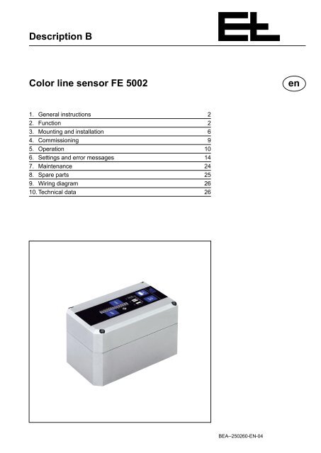
<strong>Description</strong> B<br />
<strong>Color</strong> <strong>line</strong> s<strong>en</strong>sor <strong>FE</strong> <strong>5002</strong><br />
1. G<strong>en</strong>eral instructions 2<br />
2. Function 2<br />
3. Mounting and installation 6<br />
4. Commissioning 9<br />
5. Operation 10<br />
6. Settings and error messages 14<br />
7. Maint<strong>en</strong>ance 24<br />
8. Spare parts 25<br />
9. Wiring diagram 26<br />
10. Technical data 26<br />
BEA--250260-EN-04<br />
<strong>en</strong>
<strong>Color</strong> <strong>line</strong> s<strong>en</strong>sor <strong>FE</strong> <strong>5002</strong><br />
1. G<strong>en</strong>eral instructions<br />
1.1 <strong>Description</strong><br />
1.2 Safety instructions<br />
1.3 Variants<br />
2. Function<br />
2.1 Int<strong>en</strong>ded usage<br />
2.2 Design<br />
B Page 2<br />
Explanation of symbols<br />
= jobs to be performed<br />
= important information and instructions<br />
Please keep this description in a safe place, accessible to personnel<br />
at all times.<br />
The description is part of the package supplied and should be read<br />
carefully prior to assembly, operation and maint<strong>en</strong>ance work.<br />
Never touch the edges of running webs.<br />
The color <strong>line</strong> s<strong>en</strong>sor is available in two differ<strong>en</strong>t versions.<br />
<strong>FE</strong> <strong>5002</strong> with front lighting<br />
<strong>FE</strong> <strong>5002</strong> with back lighting<br />
In both cases the s<strong>en</strong>sor is the same, only with back lighting the light<br />
transmitter is mounted in its own housing and both transmitters in the<br />
color <strong>line</strong> s<strong>en</strong>sor are switched off via parameters.<br />
In areas in which differ<strong>en</strong>ces exist betwe<strong>en</strong> the two s<strong>en</strong>sor versions,<br />
both versions will be described.<br />
The <strong>FE</strong> <strong>5002</strong> color <strong>line</strong> s<strong>en</strong>sor may only be used for the contact-free<br />
scanning of <strong>line</strong>s or contrast transitions (color contrast or web edge;<br />
see also figure). The <strong>FE</strong> <strong>5002</strong> color <strong>line</strong> s<strong>en</strong>sor is used with web<br />
guiders.<br />
Only use the <strong>FE</strong> <strong>5002</strong> color <strong>line</strong> s<strong>en</strong>sor<br />
- in perfect technical working order,<br />
- for use as int<strong>en</strong>ded.<br />
The <strong>FE</strong> <strong>5002</strong> color <strong>line</strong> s<strong>en</strong>sor mainly comprises a s<strong>en</strong>sor optical<br />
unit, color CCD array elem<strong>en</strong>t with a resolution of 3 x 2700 pixels<br />
(resolution - red, gre<strong>en</strong>, blue) and LEDs as light transmitters whereby<br />
a distinction is made betwe<strong>en</strong> front lighting, diffuse lighting and back<br />
lighting as light transmitter. Operation is via membrane keyboard.
Guiding criteria<br />
Line Line<br />
Web edge <strong>Color</strong> contrast<br />
edge<br />
2.3 Operating principle<br />
<strong>Color</strong> <strong>line</strong> s<strong>en</strong>sor operating principle<br />
S<strong>en</strong>sor optical<br />
unit<br />
Transmitter<br />
Diffuse light<br />
Membrane<br />
keyboard<br />
<strong>Color</strong> <strong>line</strong> s<strong>en</strong>sor <strong>FE</strong> <strong>5002</strong><br />
Connecting plug<br />
(accessory)<br />
Separate light transmitter<br />
(optional)<br />
Light diodes transmit light onto the web. The reflected light illuminates<br />
the color CCD array elem<strong>en</strong>t via the optical unit. In the back<br />
lighting process<br />
Illuminated by the light received, the CCD elem<strong>en</strong>ts in the color <strong>line</strong><br />
s<strong>en</strong>sor thus accept a higher signal level. The guiding criterion (<strong>line</strong> or<br />
contrasting edge) is evaluated by the microprocessor and output as<br />
an actual position value on the CAN bus. This output value may e.g.<br />
be used to control digital web guiding. At the same time, the actual<br />
position of the guiding criterion in the measuring range is display on<br />
the LED light strip.<br />
If the LED next to the LED light strip lights up gre<strong>en</strong>, the color <strong>line</strong><br />
s<strong>en</strong>sor is ready for operation.<br />
Diffuse<br />
light<br />
Web<br />
Back lighting<br />
Floodlight<br />
Transmitter<br />
Flood lighting<br />
LED light strip<br />
LED-readiness for operation<br />
B Page 3
<strong>Color</strong> <strong>line</strong> s<strong>en</strong>sor <strong>FE</strong> <strong>5002</strong><br />
2.4 <strong>Color</strong> <strong>line</strong> s<strong>en</strong>sor<br />
measuring range<br />
B Page 4<br />
orange light spots<br />
red light spot<br />
Light spots Scanning point<br />
2.5 G<strong>en</strong>eral implem<strong>en</strong>taton<br />
instructions<br />
Support roller/<br />
guide rod<br />
Scanning following a support roller/<br />
guide rod<br />
The color <strong>line</strong> s<strong>en</strong>sor measuring range amounts to max. ±10 mm and<br />
is resolved in 3 x 2700 pixels (red, gre<strong>en</strong>, blue). In the case of <strong>line</strong>s,<br />
the range in which the <strong>line</strong> may be displaced is reduced by the <strong>line</strong><br />
width.<br />
The range in which the <strong>line</strong> may be displaced is determined as follows:<br />
Range = ± (10 mm - )<br />
Line width<br />
2<br />
The color <strong>line</strong> s<strong>en</strong>sor outputs the actual position value for this range<br />
which corresponds to the position of the guiding criterion. The guiding<br />
criterion may be displaced within 75 % of the available range.<br />
The guiding criterion should always be located in the c<strong>en</strong>ter of the<br />
s<strong>en</strong>sor optical unit. The c<strong>en</strong>ter of the s<strong>en</strong>sor optical unit is marked<br />
by an orange light spot on the web. The two outer orange light spots<br />
mark the outer edges of the measuring range. The red dot indicates<br />
the position in the measuring range of the guiding criterion curr<strong>en</strong>tly<br />
being used. The light spots do not indicate the s<strong>en</strong>sor scanning point<br />
which is approx. 10 mm away from the light spots!<br />
The s<strong>en</strong>sor optical unit scanning point is located 2.5 mm outside<br />
the s<strong>en</strong>sor c<strong>en</strong>ter.<br />
In the case of a continuous guiding criterion these 10 mm are of no<br />
significance. With interruptions in criteria it must be assured that<br />
no interruption of the guiding criterion occurs at the scanning point.<br />
Wh<strong>en</strong> teaching-in a guiding criterion, in particular, this may cause<br />
problems.<br />
It is important to assure a constant distance betwe<strong>en</strong> color <strong>line</strong> s<strong>en</strong>sor<br />
and web. Scanning should always be performed in a sector in<br />
which no web height fluctuations occur. The sector immediately following<br />
a support roller/guide rod is recomm<strong>en</strong>ded.<br />
The color <strong>line</strong> s<strong>en</strong>sor recognizes all <strong>line</strong>/contrasting edges in the<br />
measuring range. One of the detected <strong>line</strong>s or contrasting edges<br />
must be selected for guiding.<br />
The color contrast betwe<strong>en</strong> <strong>line</strong>s or color contrasts to the background<br />
should always be good. Best is e.g. a black <strong>line</strong> (edge) on a white<br />
web or a white <strong>line</strong> on a black web. An extremely poor contrast would<br />
be a yellow <strong>line</strong> (edge) on an orange web.
2.6 Operating modes<br />
t i<br />
t p<br />
2.6.1 Line scanning<br />
<br />
Limited search range<br />
t i = Pulse time<br />
t p = Pulse interval<br />
Measuring<br />
range<br />
2.6.2 Contrasting edge scan<br />
<br />
Limited search range<br />
<strong>Color</strong> <strong>line</strong> s<strong>en</strong>sor <strong>FE</strong> <strong>5002</strong><br />
With color <strong>line</strong> s<strong>en</strong>sors, in principle the following operating modes<br />
may be distinguished:<br />
- Line scanning, light <strong>line</strong> on a dark background<br />
- Line scanning, dark <strong>line</strong> on a light background<br />
- Contrasting edge scanning.<br />
The guiding criterion (<strong>line</strong> or contrasting edge) may be continuous<br />
or brok<strong>en</strong>, light or dark. The interruption ratio t i /t p should be greater<br />
than 1!<br />
The <strong>line</strong> width in the case of a black, sharply defined <strong>line</strong> on a white<br />
background (or vice-versa) should be betwe<strong>en</strong> approx. 0.2 mm and<br />
max. 8 mm. The optimum <strong>line</strong> width is 2 - 3 mm. Reliable operation<br />
is assured wh<strong>en</strong> the background on one of the two sides of the <strong>line</strong> is<br />
wider than 1 mm.<br />
The finer the <strong>line</strong>, the poorer the image definition will be. In the case<br />
of <strong>line</strong>s wider than 8 mm, the "Contrasting edge" guiding criterion<br />
should be selected as the wider <strong>line</strong> can no longer be displaced.<br />
The following typical <strong>line</strong> scans are possible:<br />
continuous <strong>line</strong> with uniform background<br />
brok<strong>en</strong> <strong>line</strong> with uniform background<br />
continuous <strong>line</strong> with disturbances in background<br />
brok<strong>en</strong> <strong>line</strong> with disturbances in background<br />
Disturbances in the background may be print marks, motifs, second<br />
<strong>line</strong> with the same properties or otherwise. In this case, the measuring<br />
range may be limited via parameter ".2.9. > search range mode".<br />
The size of the limited search range is the equival<strong>en</strong>t of the <strong>line</strong><br />
width + 2 mm. The red dot indicates the c<strong>en</strong>ter of the search range.<br />
The width of a contrasting stripe must be at least 1 mm.<br />
The following typical contrasting edge scans are possible:<br />
Web edge scanning<br />
Contrasting edge with uniform background<br />
Brok<strong>en</strong> edge with uniform background<br />
Contrasting edge with disturbances in background<br />
Brok<strong>en</strong> contrasting edge with disturbances in background<br />
Disturbances in the background may be print marks, motifs, second<br />
<strong>line</strong> with the same properties or otherwise. In this case, the measuring<br />
range may be limited via parameter ".2.9. > search range mode".<br />
The size of the limited search range is 2 mm.<br />
B Page 5
<strong>Color</strong> <strong>line</strong> s<strong>en</strong>sor <strong>FE</strong> <strong>5002</strong><br />
2.7 Surface and transpar<strong>en</strong>cy<br />
Diffuse light<br />
2.8 Background panel<br />
2.9 S<strong>en</strong>sor accessories<br />
B Page 6<br />
Flood light<br />
Reflection of the light beams with reflective<br />
surfaces<br />
3. Mounting and<br />
installation<br />
This section is not relevant to color <strong>line</strong> s<strong>en</strong>sors operating on a<br />
back lighting principle.<br />
Apart from the color contrast, the surface also contributes to the s<strong>en</strong>sitivity<br />
of the color <strong>line</strong> s<strong>en</strong>sor. Highly reflective surfaces (e.g. silver<br />
film) reflect very much light, matt or rough surfaces (e.g. paper) reflect<br />
little light.<br />
In the case of highly reflective surfaces the light beams are reflected<br />
away by the structural arrangem<strong>en</strong>t of the flood light. To the color<br />
<strong>line</strong> s<strong>en</strong>sor, a silver film appears as a black film and through reflection<br />
further color information may also be lost. For this reason, a light<br />
guiding criterion, e.g. a white <strong>line</strong>, is best suited to highly reflective<br />
surfaces.<br />
If, in such cases, no light guiding criterion is available, the color <strong>line</strong><br />
s<strong>en</strong>sor automatically uses diffuse light whereby the reflected light is<br />
evaluated (see figure on left). A silver film acts as a mirror. Due to<br />
this mirror effect, the s<strong>en</strong>sor sees the pale diffuse light. With it, highly<br />
reflective surfaces appear light.<br />
This section is not relevant for color <strong>line</strong> s<strong>en</strong>sors operating on a<br />
back lighting principle.<br />
If scanning is always within a non-transpar<strong>en</strong>t web, no panel is necessary.<br />
On non-transpar<strong>en</strong>t webs on which the edge or close to it is to be<br />
scanned, a matt black background panel should be used.<br />
With dark <strong>line</strong>s (black or shiny silver) on transpar<strong>en</strong>t webs a light<br />
background panel is necessary (the transpar<strong>en</strong>t section appears<br />
light).<br />
<strong>Color</strong> <strong>line</strong> s<strong>en</strong>sor accessories include the connection cable and the<br />
following s<strong>en</strong>sor holders:<br />
Type Securing Mounting<br />
VA 6007 20 x 20 mm rigid<br />
VA 6027 20 x 20 mm flexible<br />
VA 6107 40 x 40 mm rigid<br />
VA 6127 40 x 40 mm flexible<br />
Please observe the locally applicable and professional safety<br />
and accid<strong>en</strong>t prev<strong>en</strong>tion regulations.<br />
Section "3. Mounting and installation" may be omitted for color <strong>line</strong><br />
s<strong>en</strong>sors ready mounted mechanically on delivery with adjusting<br />
screws secured by screw locking varnish.
3.1 G<strong>en</strong>eral mounting<br />
instructions<br />
Setting template<br />
Web<br />
Setting position<br />
Web Knurled<br />
screw<br />
Süpport roller<br />
same angle<br />
Web<br />
Markng in the setting<br />
template<br />
<strong>Color</strong> <strong>line</strong> s<strong>en</strong>sor <strong>FE</strong> <strong>5002</strong><br />
In observance of the following assembly instructions mount the<br />
color <strong>line</strong> s<strong>en</strong>sor in the first third of the exit section of the web<br />
guider (see also actuating elem<strong>en</strong>t description).<br />
In order to avoid height fluctuations scanning must always be performed<br />
immediately following a support roller/guide rod. Please<br />
<strong>en</strong>sure that the distance to the web in the side adjustm<strong>en</strong>t range<br />
of the color <strong>line</strong> s<strong>en</strong>sor does not change.<br />
To assure correct function the color <strong>line</strong> s<strong>en</strong>sor must be mounted at a<br />
distance of 24.6 mm and angle of 14° to the web. A red plastic setting<br />
template is located on the s<strong>en</strong>sor for setting these dim<strong>en</strong>sions. Setting<br />
is performed as follows:<br />
Unscrew the setting template from the color <strong>line</strong> s<strong>en</strong>sor and insert<br />
in the setting position.<br />
Set the s<strong>en</strong>sor to the required scanning position and tight<strong>en</strong> the<br />
knurled screw.<br />
Loos<strong>en</strong> the adjusting screws on the movable s<strong>en</strong>sor fixture and<br />
position the s<strong>en</strong>sor on the web so that the setting template rests<br />
flush with the web. In the case of the fixed s<strong>en</strong>sor fixture the distance<br />
must be set via the correct positioning of the s<strong>en</strong>sor fixture!<br />
If the web is scanned on a support roller the marking in the setting<br />
template must rest exactly on the roller. The inclination must be at<br />
approx. the same angle at both sides.<br />
On completion of setting work, screw the setting template securely<br />
to the color <strong>line</strong> s<strong>en</strong>sor.<br />
Due to the arrangem<strong>en</strong>t of the diffuse light transmitter the s<strong>en</strong>sor<br />
may only be inc<strong>line</strong>d in the direction illustrated (observe front/rear<br />
view). If the s<strong>en</strong>sor is inc<strong>line</strong>d in the other direction during mounting,<br />
the diffuse light transmitter cannot function. For the back lighting<br />
process the s<strong>en</strong>sor must also be inc<strong>line</strong>d in this direction. The<br />
web must run at an angle of 90° to the color <strong>line</strong> s<strong>en</strong>sor.<br />
Rear view Front view<br />
Web<br />
B Page 7
<strong>Color</strong> <strong>line</strong> s<strong>en</strong>sor <strong>FE</strong> <strong>5002</strong><br />
3.2 Mounting instructions for<br />
back lighting transmitters<br />
3.3 Installation<br />
Assembly<br />
drill holes<br />
Earth connection<br />
3.4 Sharpness setting<br />
B Page 8<br />
Mount back lighting transmitter as illustrated.<br />
In confined mounting spaces the transmitter may be rotated at an<br />
angle of 30° around the pivot. The amount of light received by the<br />
color <strong>line</strong> s<strong>en</strong>sor will however be reduced a little as a result.<br />
The color <strong>line</strong> s<strong>en</strong>sor differ<strong>en</strong>tiates betwe<strong>en</strong> light and dark <strong>line</strong>s<br />
and contrasting edges. For this reason s<strong>en</strong>sors used in the back<br />
lighting process must be directly aligned to the back lighting transmitter<br />
lamps as otherwise a suffici<strong>en</strong>t amount of light cannot be<br />
assured.<br />
Please <strong>en</strong>sure that the insulation is not damaged and leads are<br />
properly secured and protected. Protect and run signal <strong>line</strong>s away<br />
from heavy-curr<strong>en</strong>t carrying leads .<br />
The color <strong>line</strong> s<strong>en</strong>sor housing with drill holes (see figure opposite)<br />
must be connected to the machine frame. Due to the metal connection,<br />
heat dissipation via the assembly connection may additionally<br />
occur.<br />
Run the electrical leads according to the attached wiring diagram<br />
and protect with a strain release device.<br />
Tight<strong>en</strong> the connection lead union nut. It assures a conductive<br />
connection betwe<strong>en</strong> the color <strong>line</strong> s<strong>en</strong>sor housing and the signal<br />
<strong>line</strong> shield.<br />
The sharpness setting must be performed for precision color<br />
<strong>line</strong> s<strong>en</strong>sor operation!<br />
Connect web guider to the operating voltage.<br />
Pivot<br />
Position s<strong>en</strong>sor on the web. The guiding criterion that is to be<br />
scanned must be located at the position of the middle orange light<br />
spot (set position).<br />
As guiding criterion for the sharpness setting we recomm<strong>en</strong>d an<br />
uniform black <strong>line</strong> on a white background, with a <strong>line</strong> width of<br />
1 mm. If such a guiding criterion is not available, a simple paper<br />
print-out may be used as a substitute. If using a paper print-out<br />
please <strong>en</strong>sure that the paper is clean (without creases and folds)<br />
and rests on the web at the correct distance.
Poor sharpness<br />
(few LEDs)<br />
LEDs 7+ 8 flash<br />
Good sharpness<br />
(Several LEDs)<br />
4. Commissioning<br />
4.1 CAN Address<br />
GRP = Group number<br />
DEV = Device number<br />
Device 3<br />
Standard<br />
device<br />
number<br />
Colour <strong>line</strong><br />
s<strong>en</strong>sor = 3<br />
Group<br />
e.g. 0<br />
<strong>Color</strong> <strong>line</strong> s<strong>en</strong>sor <strong>FE</strong> <strong>5002</strong><br />
Press the "S<strong>en</strong>sor" and "SETUP" keys simultaneously. The guiding<br />
criterion is taught. After approx. 1 second both keys may be<br />
released.<br />
Move the s<strong>en</strong>sor by approx. 5 mm to the left or right. The red dot<br />
must remain on the guiding criterion. If the dot does not remain on<br />
the guiding criterion it must be re-taught.<br />
Press and hold down the "SETUP" key and additionally press the<br />
"GRP" key. Release both keys.<br />
LEDs 7 and 8 flash in alternation, the remaining LEDs indicate the<br />
sharpness. The more LEDs light up the better the sharpness. If<br />
only a few LEDs light up, by changing the distance betwe<strong>en</strong> the<br />
color <strong>line</strong> s<strong>en</strong>sor to the web, sharpness may be improved.<br />
Press the "SETUP" key once and the display will quit the sharpness<br />
setting.<br />
On compact systems planned by E+L (e.g. DR 24..) no settings<br />
are necessary on first-time commissioning.<br />
If the color <strong>line</strong> s<strong>en</strong>sor is ordered individually and connected with further<br />
control compon<strong>en</strong>ts to form a functioning control loop, on commissioning<br />
the color <strong>line</strong> s<strong>en</strong>sor for the first time, the CAN address<br />
must be checked.<br />
The s<strong>en</strong>sor group number must be id<strong>en</strong>tical to that of the digital guider<br />
to which it belongs (see block diagram).<br />
Switch the guider to "c<strong>en</strong>ter" mode.<br />
Press the "GRP" and "DEV" buttons on the color <strong>line</strong> s<strong>en</strong>sor at<br />
the same time and hold them down. After approx. 6 seconds the<br />
group and device numbers will begin to flash on the display (LED<br />
light strip). After approx. a further 20 seconds the color <strong>line</strong> s<strong>en</strong>sor<br />
will switch into set-up mode. The flashing becomes a perman<strong>en</strong>t<br />
light and the group number may be changed via the "GRP" key<br />
and the device number via the "DEV" key.<br />
The following device number <strong>en</strong>tries are possible:<br />
1 = right s<strong>en</strong>sor (operation possible on s<strong>en</strong>sor only)<br />
2 = left s<strong>en</strong>sor (operation possible on s<strong>en</strong>sor only)<br />
3 = color <strong>line</strong> s<strong>en</strong>sor (standard)<br />
If the "GRP" and "DEV" keys are not pressed for longer than approx.<br />
20 seconds, the group and device numbers are stored and<br />
setup mode quit again.<br />
B Page 9
<strong>Color</strong> <strong>line</strong> s<strong>en</strong>sor <strong>FE</strong> <strong>5002</strong><br />
5. Operation<br />
5.1 Operating instructions<br />
B Page 10<br />
Operating modes<br />
The color <strong>line</strong> s<strong>en</strong>sor may only be positioned wh<strong>en</strong> the machine<br />
is stationary!<br />
The operating sequ<strong>en</strong>ce is the same for each guiding criterion. Wh<strong>en</strong><br />
addressing as a color <strong>line</strong> s<strong>en</strong>sor (X.3) operation may be performed<br />
both from the s<strong>en</strong>sor and command station DO 10.. / DO 200.. .<br />
Wh<strong>en</strong> teaching the guiding criterion for safety reasons the web<br />
should not be moved. In the case of brok<strong>en</strong> guiding criteria please<br />
<strong>en</strong>sure that during teaching no break in the guiding criterion occurs<br />
at the s<strong>en</strong>sor scanning point. If this is not possible, the guiding<br />
criterion may be taught during the processing speed in observance<br />
of all the safety requirem<strong>en</strong>ts.<br />
If a transpar<strong>en</strong>t web or guiding criterion is being scanned, a background<br />
panel/support roller must be used. The color (white/black)<br />
of the background panel/support roller may be established in the<br />
following table.<br />
The following table is also highly suitable for manual teaching to<br />
assure that the correct operating mode is selected.<br />
Panel/roller in background<br />
(no , white or black )<br />
Guiding Background<br />
criterion support material<br />
light dark X X<br />
light reflective X X<br />
light transpar<strong>en</strong>t X X<br />
dark light X X<br />
dark reflective X X<br />
dark transpar<strong>en</strong>t X X<br />
reflective dark X X<br />
reflective light X X<br />
reflective transpar<strong>en</strong>t X X X X<br />
transpar<strong>en</strong>t dark X X<br />
transpar<strong>en</strong>t light X X<br />
transpar<strong>en</strong>t reflective X X X X<br />
Operating mode and panel selection for<br />
front lighting process<br />
Guiding criterion Background/support material<br />
Line not transpar<strong>en</strong>t transpar<strong>en</strong>t X<br />
Line transpar<strong>en</strong>t not transpar<strong>en</strong>t X<br />
<strong>Color</strong> not transpar<strong>en</strong>t transpar<strong>en</strong>t X<br />
<strong>Color</strong> transpar<strong>en</strong>t not transpar<strong>en</strong>t X<br />
Operating mode selection for back lighting<br />
process<br />
Line Contrasting edge
5.2 Teaching the guiding<br />
criterion<br />
5.2.1 Automatic teaching<br />
desired guiding criterion<br />
red dot two red dots<br />
+<br />
<strong>Color</strong> <strong>line</strong> s<strong>en</strong>sor <strong>FE</strong> <strong>5002</strong><br />
The guiding criterion that is to scan the color <strong>line</strong> s<strong>en</strong>sor must be<br />
taught. This taught guiding criterion remains stored until a new teaching<br />
process takes place. A guiding criterion may be stored for each<br />
of the three operating modes (light <strong>line</strong>, dark <strong>line</strong>, color contrast). The<br />
three following methods of detecting and storing the guiding criterion<br />
are available:<br />
5.2.1 Automatic teaching (standard)<br />
5.2.2 Manual teaching<br />
5.2.3 Combined teaching<br />
If the customer wishes manual or combined teaching the appropriate<br />
value must be selected in parameter ".2.0. >Teaching Mode" of the<br />
color <strong>line</strong> s<strong>en</strong>sor.<br />
As a special application (e.g. drop stitch, water mark, perforated <strong>line</strong>)<br />
there is still in parameter ".2.0. >Teaching Mode" the value 3 (no<br />
teaching possible). With this setting no guiding criterion is taught or<br />
stored. The guiding criterion detected as being best by the s<strong>en</strong>sor<br />
becomes the guiding criterion. If the s<strong>en</strong>sor th<strong>en</strong> detects a better<br />
one, it will change to it.<br />
The actuating elem<strong>en</strong>t is always switched to "manual" mode<br />
wh<strong>en</strong> a guiding criterion is being taught.<br />
Connect the web guider to the operating voltage.<br />
Position the s<strong>en</strong>sor on the web. The guiding criterion that is to be<br />
scanned must be located at the position of the middle orange light<br />
spot (set position).<br />
The color <strong>line</strong> s<strong>en</strong>sor operates according to <strong>line</strong> priority. In the<br />
case of contrasting edges therefore it may be that <strong>line</strong>s are detected<br />
in the guiding criterion or background. If the s<strong>en</strong>sor is positioned<br />
approx. 2 mm to the left or right next to the contrasting<br />
edge improved teaching of contrasting edges in assured.<br />
Press the "S<strong>en</strong>sor" and "SETUP" keys at the same time. The<br />
guiding criterion is taught. After approx. 1 second both keys may<br />
be released. Teaching is completed. If teaching is performed on<br />
moving webs for difficult guiding criteria (e.g. brok<strong>en</strong>) both keys<br />
must be held down longer (e.g. 5 seconds).<br />
If the guiding criterion has be<strong>en</strong> detected, the red dot is also located<br />
on the guiding criterion or two red dots <strong>en</strong>close the guiding criterion.<br />
The red light spot follows the guiding criterion. The LED light strip indicates<br />
the curr<strong>en</strong>t position of the guiding criterion.<br />
B Page 11
<strong>Color</strong> <strong>line</strong> s<strong>en</strong>sor <strong>FE</strong> <strong>5002</strong><br />
5.2.2 Manual teaching<br />
B Page 12<br />
+<br />
Position the s<strong>en</strong>sor on the web. The guiding criterion that is to be<br />
scanned must be in the scanning range (betwe<strong>en</strong> the two outer<br />
orange light spots) of the color <strong>line</strong> s<strong>en</strong>sor.<br />
Please pay particular att<strong>en</strong>tion to section "2.4 <strong>Color</strong> <strong>line</strong> s<strong>en</strong>sor<br />
measuring range" distance betwe<strong>en</strong> scanning point and light spots<br />
Establish the property of the guiding criterion (light <strong>line</strong>, dark <strong>line</strong>,<br />
color contrast) and the background/support material and determine<br />
the appropriate operating mode from the "Operating mode<br />
and panel selection" table. Select the required operating mode<br />
with the s<strong>en</strong>sor key. The gre<strong>en</strong> LED arrow beside the selected<br />
guiding criterion lights up.<br />
Press the "SETUP" key and additionally the "S<strong>en</strong>sor" key. After<br />
approx. 1 second both keys may be released. The guiding criterion<br />
is taught while the keys are pressed. If teaching difficult guiding<br />
criteria (brok<strong>en</strong>) on moving webs, both keys must be held down<br />
longer (e.g. 5 seconds). The gre<strong>en</strong> LED arrow next to the selected<br />
guiding criterion flashes. The red light dot indicates the best guiding<br />
criterion detected in the s<strong>en</strong>sor scanning range.<br />
Select the required guiding criterion that is to be scanned by<br />
pressing the "GRP" or "DEV" key. The red dot indicates the appropriate<br />
guiding criterion.<br />
During selection the LEDs in the LED strip flash. The more LEDs<br />
flash the better the guiding criterion has be<strong>en</strong> recognized. Dep<strong>en</strong>ding<br />
on whether flood or diffuse lighting is being used for scanning,<br />
various numbers of LEDs may flash for the same guiding<br />
criterion. In any case, selection should always be on the basis of<br />
as many LEDs flashing as possible.<br />
In acknowledgem<strong>en</strong>t, press the s<strong>en</strong>sor key once. The guiding criterion<br />
is stored, the gre<strong>en</strong> LED arrow goes on. The red light spot<br />
follows the guiding criterion. After acknowledgem<strong>en</strong>t the LED strip<br />
indicates the curr<strong>en</strong>t position of the guiding criterion.<br />
Two <strong>line</strong> scanning modes are available (light <strong>line</strong>/dark <strong>line</strong>). If<br />
assignm<strong>en</strong>t as a light or dark <strong>line</strong> cannot clearly be determined,<br />
the teaching process should be performed with both operating<br />
modes. The operating mode that detects the guiding criterion better<br />
must th<strong>en</strong> be selected to scan it.
5.2.3 Combined teaching<br />
5.3 Operation in conjunction<br />
with a web guider<br />
5.4 Manual lamp selection<br />
+<br />
+<br />
<strong>Color</strong> <strong>line</strong> s<strong>en</strong>sor <strong>FE</strong> <strong>5002</strong><br />
In the case of combined teaching, teaching may be both automatic<br />
and manual. Perform teaching required as described in section 5.2.1<br />
or 5.2.2. Please note with regard to the key sequ<strong>en</strong>ce on teaching:<br />
If teaching is automatic, first the "S<strong>en</strong>sor" and th<strong>en</strong> additionally the<br />
"SETUP" key must be pressed.<br />
If teaching is to be manual, it is exactly the reverse. First the<br />
"SETUP" key and th<strong>en</strong> the "S<strong>en</strong>sor" key must be pressed.<br />
Switch the web guider to "C<strong>en</strong>ter" mode.<br />
Insert the web.<br />
Position the color <strong>line</strong> s<strong>en</strong>sor.<br />
Position the color <strong>line</strong> s<strong>en</strong>sor on the taught guiding criterion so<br />
that it is in the c<strong>en</strong>ter of the s<strong>en</strong>sor optical unit (middle orange<br />
spot).<br />
Select operating mode (light <strong>line</strong>, dark <strong>line</strong>, contrasting edge).<br />
Switch the web guider to "automatic" mode.<br />
If the color <strong>line</strong> s<strong>en</strong>sor loses the guiding criterion, LEDs 0 and 8 in<br />
the LED strip will flash and the guider is inhibited.<br />
Set web offset / position actuating elem<strong>en</strong>t.<br />
The "GRP/DEV" keys may be used to set a web offset in "automatic"<br />
mode.<br />
In "manual" mode the actuating elem<strong>en</strong>t may be positioned.<br />
The "GRP" key effects an offset away from the s<strong>en</strong>sor, the "DEV"<br />
towards the s<strong>en</strong>sor.<br />
If a brok<strong>en</strong> guiding criterion is taught while the web is moving a "stroboscopic<br />
effect" may be caused. During the front lighting phase the<br />
s<strong>en</strong>sor only sees the <strong>line</strong> and during the diffuse light phase only the<br />
interruption. The s<strong>en</strong>sor cannot therefore detect the guiding criterion.<br />
In the case of manual lamp selection immediately prior to teaching a<br />
light transmitter is selected that does not change for the duration of<br />
the teaching process. Manual lamp selection is performed as follows:<br />
Press the "Setup" key and th<strong>en</strong> additionally press the "DEV" key<br />
repeatedly until the required light transmitter is selected.<br />
The teaching of the guiding criterion must th<strong>en</strong> be started within<br />
10 seconds. If no guiding criterion is taught within this period the<br />
s<strong>en</strong>sor will th<strong>en</strong> reselect the stored (most rec<strong>en</strong>tly taught) light<br />
transmitter.<br />
B Page 13
<strong>Color</strong> <strong>line</strong> s<strong>en</strong>sor <strong>FE</strong> <strong>5002</strong><br />
6. Settings and error<br />
messages<br />
6.1 Parameters<br />
No. Name Default Min Max Unit <strong>Description</strong><br />
B Page 14<br />
In setup mode, setup parameters may be displayed and to some<br />
ext<strong>en</strong>t changed. To access the color <strong>line</strong> s<strong>en</strong>sor setup mode a command<br />
station DO ...., a digital controller DC 55.. or an operating<br />
panel RT .... is required.<br />
The parameter numbers are listed in the No field of the table, in the<br />
Name field the abbreviations. The Default field indicates the standard<br />
settings, Min and Max are the respective permissible limit values.<br />
The unit is indicated in the Unit field. The <strong>Description</strong> explains<br />
the function of the parameter. A dot (•) after the parameter number<br />
indicates a display parameter the value of which cannot be changed.<br />
..0. edit device 3 1 3 hex Device number (see wiring diagram)<br />
..1. edit group 0 0 7 hex Group number (see wiring diagram)<br />
..2. reset settings 0 0 2 - Works settings:<br />
0 = no function<br />
1 = E+L basic settings<br />
2 = internal value specification (Default)<br />
..3. start service 0 0 199 - Field for starting a function:<br />
0 = no function<br />
1 = reset<br />
2 = store parameters<br />
..4. <strong>Color</strong> Line S<strong>en</strong>sor - - - - Software version<br />
..5. mounting 0 0 1 - reverse s<strong>en</strong>sor signal<br />
norm/rev 0 = normal<br />
1 = reversed<br />
..6. • resolution abs. 2000 0 2700 - available s<strong>en</strong>sor measuring range in pixels<br />
..7. • range +/- 10 0 10 mm available s<strong>en</strong>sor measuring range in mm =<br />
max. s<strong>en</strong>sor measuring range - width of guiding crit.<br />
(e.g. 10 mm - 1 mm = 9 mm; display 9)<br />
..8. • s<strong>en</strong>sor value 0,00 -10,00 10,00 mm Actual position of the guiding criterion in mm<br />
..9. • > errorcode 0 0 299 - Error code:<br />
Units' places indicate exposure errors<br />
..0 = no error<br />
..2 = under-exposed<br />
..3 = over-exposed ( direct light on the optical unit)<br />
T<strong>en</strong>s' places indicate the operating status<br />
0. = guiding criterion found<br />
2. = no guiding criterion found<br />
Hundreds' places inidcate the temperature<br />
0.. = normal temperature<br />
2.. = too high temperature (> 80 °C)<br />
.1.0. monitoring - - - - Parameter title<br />
.1.1. • running time meter 0 0 65335 h Running time meter<br />
.1.2. • reset counter 0 0 32767 - Reset counter (for service personnel only)<br />
(increases by 1 resp. in ev<strong>en</strong>t of a reset)
No. Name Default Min Max Unit <strong>Description</strong><br />
.1.3. • supply voltage 0 0 40,96 V S<strong>en</strong>sor operating voltage display<br />
.1.4. • temperature 0 -40 100 °C PCB temperature in °C<br />
<strong>Color</strong> <strong>line</strong> s<strong>en</strong>sor <strong>FE</strong> <strong>5002</strong><br />
.1.5. • sharpness 0 0 16 - Optical sharpness of the guiding criterion<br />
Note: a high value in this parameter is more important<br />
than a high value in parameter .1.6.<br />
.1.6. • perc<strong>en</strong>t of valid 0 0 100 % Guiding criterion detected to X per c<strong>en</strong>t<br />
The frequ<strong>en</strong>cy of how oft<strong>en</strong> the guiding criterion was<br />
detected is indicated in per c<strong>en</strong>t.<br />
Note: 70 % for a brok<strong>en</strong> guiding criterion is a good value.<br />
.1.7. • dsp scan status 0 0 5 - Status feedback from DSP(for service personnel only)<br />
.1.8. • dsp reason of lost 0 0 10 - Reason for lost guiding criterion<br />
0 = no guiding criterion in s<strong>en</strong>sor scanning range<br />
1 = only one edge of a <strong>line</strong> detected<br />
2 = fluctuating signal, no guiding criterion may be clearly<br />
detected<br />
3 = Line tolerance exceeded<br />
4 = Brightness tolerance exceeded<br />
5 = Tolerance for standardised contrast exceeded<br />
6 = Colour tolerance red/gre<strong>en</strong>, one <strong>line</strong> or left of<br />
contrasting edge exceeded<br />
7 = Colour tolerance blue/gree, one <strong>line</strong> or left of<br />
contrasting edge exceeded<br />
8 = Colour tolerance red/gre<strong>en</strong>, right of contrasting<br />
edge exceeded<br />
9 = Colour tolerance blue/gre<strong>en</strong>, right of contrasting<br />
edge exceeded<br />
10 = Guiding criterion detected<br />
.1.9. working parameters - - - - Parameter title<br />
.2.0. > teaching mode 0 0 3 - Selection of teaching mode<br />
0 = automatic teaching<br />
1 = manual teaching<br />
2 = combined teaching (manual and automatic)<br />
3 = no teaching possible the best guiding criterion<br />
detected in the measuring range is adopted as the<br />
guiding criterion<br />
.2.1. <strong>en</strong>ergetic IIR-tau 0,22 0,05 2,00 mm IIR time constant<br />
Narrow <strong>line</strong>s are damp<strong>en</strong>ed.<br />
Note: this parameter is only active if value 3<br />
is selected in parameter .2.0..<br />
.2.2. <strong>en</strong>ergetic mov 2,00 0,05 5,00 mm Evaluation width<br />
AV width Wide <strong>line</strong>s are damp<strong>en</strong>ed<br />
Note: This parameter is only active if value 3 is selected in<br />
parameter .2.0..<br />
.2.3. <strong>line</strong> width minimum 0,12 0,12 7,00 mm Minimum <strong>line</strong> width during teaching<br />
Line thickness less than this value will not be accepted.<br />
.2.4. <strong>line</strong> width maximum 8,00 0,50 12,00 mm Maximum <strong>line</strong> width during teaching<br />
Line width greater than this value will not be accepted.<br />
.2.5. • <strong>line</strong> width actual - 0,00 8,00 mm Display of <strong>line</strong> width (during contrasting edge scanning<br />
display 0.00 is indicated)<br />
B Page 15
<strong>Color</strong> <strong>line</strong> s<strong>en</strong>sor <strong>FE</strong> <strong>5002</strong><br />
No. Name Default Min Max Unit <strong>Description</strong><br />
.2.6. • > dsp guiding mode 2 0 3 - Operating mode display<br />
0 = no operating mode (must not occur)<br />
1 = light <strong>line</strong> on dark background<br />
2 = dark <strong>line</strong> on light background<br />
3 = contrasting edge scanning<br />
.2.7. lock guiding mode 0 0 1 - Operating mode locking<br />
0 = no locking<br />
1 = operating mode locked<br />
Limitation: locking is only possible wh<strong>en</strong> addressing the<br />
color <strong>line</strong> s<strong>en</strong>sor as an edge s<strong>en</strong>sor (x.1 or. x.2).<br />
.2.8. reserve - - - - reserve<br />
.2.9. > search range 3 0 3 - Search range limitations<br />
mode 0 = no search range limitation<br />
1 = search range limitation always active<br />
2 = search range limitation only active in automatic<br />
mode. Search range is ext<strong>en</strong>ded to total s<strong>en</strong>sor<br />
measuring range if no guiding criterion is found in the<br />
defined time (parameter 30) during automatic mode.<br />
3 = Search range limitation active<br />
Search range is ext<strong>en</strong>ded to total s<strong>en</strong>sor measuring<br />
range if no guiding criterion is found in the defined<br />
time (parameter 30) during automatic mode.<br />
.3.0. full r. time 500 10 500 ms Time after loss of guiding criterion in which search range is<br />
(x5 ms) ext<strong>en</strong>ded to total s<strong>en</strong>sor measuring range<br />
.3.1. • calibration value 705 0 1350 - S<strong>en</strong>sor zero position calibration (for E+L service <strong>en</strong>gineers<br />
only)<br />
.3.2. bright <strong>line</strong> tol. - - - - Parameter title<br />
.3.3. bl width tolerance 20 1 100 % Line width tolerance for light <strong>line</strong>s<br />
.3.4. bl bright tolerance 60 40 100 % Brightness tolerance for light <strong>line</strong>s<br />
.3.5. bl contrast tol 35 1 100 % Brightness standardised contrast (SC) tolerance for light<br />
<strong>line</strong>s<br />
.3.6. > bl dsp comp. 0 0 1 - Brightness edge evaluation<br />
mode 0 = edge evaluation ON<br />
1 = edge evaluation OFF<br />
.3.7. bl color tolerance 1,3 1,1 10 - <strong>Color</strong> tolerance for red/gre<strong>en</strong> and blue/gre<strong>en</strong> for light <strong>line</strong>s<br />
.3.8. reserve - - - - reserve<br />
.3.9. dark <strong>line</strong> tol. - - - - Parameter title<br />
.4.0. dl width tolerance 20 1 100 % Line width tolerance for dark <strong>line</strong>s<br />
.4.1. dl bright tolerance 60 40 100 % Brightness tolerance for dark <strong>line</strong>s<br />
.4.2. dl contrast tol 35 1 100 % Brightness standardised contrast (SC) for dark <strong>line</strong>s<br />
.4.3. > dl dsp comp. 0 0 1 - Brightness edge evaluation<br />
mode 0 = edge evaluation ON<br />
1 = edge evaluation OFF<br />
.4.4. dl color 1,3 1,1 10 - <strong>Color</strong> tolerance for red/gre<strong>en</strong> and blue/gre<strong>en</strong> tolerance<br />
for dark <strong>line</strong>s<br />
.4.5. reserve - - - - reserve<br />
B Page 16
No. Name Default Min Max Unit <strong>Description</strong><br />
.4.6. contrast tol. - - - - Parameter title<br />
.4.7. c bright tolerance 60 40 100 % Brightness tolerance for contrasting edges<br />
<strong>Color</strong> <strong>line</strong> s<strong>en</strong>sor <strong>FE</strong> <strong>5002</strong><br />
.4.8. c contrast tol 35 1 100 % Brightness standardised contrast (SC) tolerance<br />
for contrasting edges<br />
.4.9. > c dsp comp. mode 0 0 1 - Brightness edge evaluation<br />
0 = edge evaluation ON<br />
1 = edge evaluation OFF<br />
.5.0. c color tolerance 1,3 1,1 10 - <strong>Color</strong> tolerance for red/gre<strong>en</strong> and blue/gre<strong>en</strong><br />
for contrasting edges<br />
.5.1. reserve - - - - reserve<br />
.5.2. canmon scan - - - - Parameter title<br />
.5.3. canmon mid of scan 0,00 -5,00 5,00 mm The s<strong>en</strong>sor scan axis intersection in Canmon may be<br />
offset to the left (negative value) or right (positive value).<br />
.5.4. canmon zoom scan 1 1 2 - Zoom function<br />
1 = total measuring range in s<strong>en</strong>sor scan<br />
2 = half measuring range in s<strong>en</strong>sor scan with double<br />
resolution<br />
.5.5. canmon delta scan 0 0 3 - Instead of the three colours red, blue, gre<strong>en</strong>, the<br />
differ<strong>en</strong>tiated scan is displayed on-scre<strong>en</strong>.<br />
0 = all three colours are normally displayed<br />
1 = Differ<strong>en</strong>tiated scan displayed in red<br />
2 = Differ<strong>en</strong>tiated scan displayed in gre<strong>en</strong><br />
3 = Differ<strong>en</strong>tiated scan displayed in blue<br />
.5.6. reserve - - - - reserve<br />
.5.7. web lighting - - - - Parameter title<br />
.5.8. > web lighting mode 1 0 3 - Type of lighting<br />
0 = constantly changing (flood light, diffuse light,<br />
no lighting, flood light, diffuse light, no lighting,<br />
flood light etc.)<br />
1 = only flood lighting<br />
2 = only diffuse lighting<br />
3 = external lighting (back lighting) or no lighting, only<br />
external lighting (e.g. daylight, machine lighting etc.)<br />
.5.9. web lighting fixed 0 0 1 - Lighting mode locked<br />
0 = <strong>en</strong>abled<br />
1 = locked<br />
.6.0. external can lamp 0 0 2 - Type of external lighting<br />
0 = no external lighting<br />
1 = passive external lighting (exposure time is controlled<br />
2 = microprocessor-contr. back lighting transmitter<br />
(optional)<br />
.6.1. • exposure time 5,000 5,000 10,000 ms Exposure time<br />
.6.2. offset ADC -5 -31 31 - S<strong>en</strong>sor zero point offset (only for E+L serv. <strong>en</strong>gineers)<br />
.6.3. gain ADC 18 0 63 - CCD analog signal gain (only for E+L service <strong>en</strong>gineers)<br />
.6.4. • I-led flood light 20,00 0,00 40,96 mA If value 4 is not achieved, (only if flood light - transmitter is<br />
in operation), one of the flood light transmitter LEDs may<br />
be defective.<br />
B Page 17
<strong>Color</strong> <strong>line</strong> s<strong>en</strong>sor <strong>FE</strong> <strong>5002</strong><br />
No. Name Default Min Max Unit <strong>Description</strong><br />
.6.5. • U-led flood light 10,8 0,00 40,96 V If the display drops below 8, the light transmitter is defective<br />
(only if the flood light transmitter is in operation)<br />
.6.6. • I-led diffuse light 14,00 0,00 40,96 mA If value 4 is not achieved, (only if diffuse light transmitter is<br />
in operation), one of the diffuse light transmitter LEDs may<br />
be defective<br />
.6.7. • U-led diffuse light 10,8 0,00 40,96 V If the display drops below 8,the light transmitter is defective<br />
(only if the diffuse light transmitter is in operation).<br />
.6.8. trouble shooting - - - - Parameter title<br />
.6.9. • perc<strong>en</strong>t good dma 100,0 0,00 100,0 % Operational safety of the CCD data flow<br />
If the value of 100.0 is not achieved, a massive hard or<br />
software problem has aris<strong>en</strong>.<br />
.7.0. • status lm 9822 0 -1 1 - Serial programming of AD converter LM 9822<br />
0 = not performed<br />
1 = performed and error-free<br />
-1 = performed and error-free<br />
.7.1. • hardware test 0000 0000 FFFF hex Self test result<br />
.7.2. dsp emulator 0 0 1 - DSP watchdog ON/OFF<br />
0 = on<br />
1 = off<br />
.7.3. no invalid 0 0 1 - Att<strong>en</strong>tion: only for special application<br />
Actuating elem<strong>en</strong>t blocking With value "1" actuating<br />
elem<strong>en</strong>t will not be blocked on loss of the guiding criterion.<br />
May only be used for special applications.<br />
.7.4. <strong>line</strong> as two edges 0 0 1 - Att<strong>en</strong>tion: only for special application<br />
Line width monitoring (only possible with DI 9022)<br />
0 = Line width monitoring OFF<br />
1 = Line width monitoring ON<br />
.7.5. <strong>line</strong> ATE lowpass 5 0 8 - Att<strong>en</strong>tion: only for special application<br />
Smoothing of <strong>line</strong> edge signal and higher resolution. Only<br />
active with <strong>line</strong> width monitoring<br />
.7.6. resolution pitch 45 40 50 - Att<strong>en</strong>tion: only for special application<br />
Fine adjustm<strong>en</strong>t of <strong>line</strong> width output<br />
If <strong>line</strong> width output deviates from the actual <strong>line</strong> width the<br />
output may be changed with this parameter.<br />
Parameter value list (Selection list)<br />
B Page 18<br />
If a ">" symbol is indicated in front of the parameter, it may be<br />
edited in CANMON with the help of a parameter value list (selection<br />
list). Select the "Value" field and op<strong>en</strong> the parameter value list<br />
via the <strong>en</strong>ter key. Use the cursor keys to select the required parameter<br />
value, press the spacebar to mark the parameter value.
6.2 Optimising and setting<br />
specific parameters<br />
<strong>Color</strong> <strong>line</strong> s<strong>en</strong>sor <strong>FE</strong> <strong>5002</strong><br />
In the case of clear guiding criteria no changes to the following<br />
parameters are necessary. To display the s<strong>en</strong>sor scan<br />
and optimize parameters a CANMON program or command<br />
station DO 2000 is required.<br />
Default values are selected so that the majority of guiding criteria<br />
may be detected. As guiding criteria are mostly subject to certain<br />
fluctuations the individual tolerances are wide. Nevertheless in order<br />
to id<strong>en</strong>tify the guiding criterion with great reliability the guiding<br />
criterion must adhere to all tolerances.<br />
The effect of changes in the relevant parameters may be checked<br />
immediately in parameter "DSP reason of lost" and "per c<strong>en</strong>t of valid"<br />
Att<strong>en</strong>tion: a "per c<strong>en</strong>t of valid" of 100 % may not be achieved by<br />
wid<strong>en</strong>ing the tolerances (increasing parameter values). A "per c<strong>en</strong>t of<br />
valid" of 70 % is a very good value! At 15 % guiding still works (e.g.<br />
brok<strong>en</strong> guiding criterion).<br />
If tolerances are wid<strong>en</strong>ed the s<strong>en</strong>sor will no longer be able to distinguish<br />
differ<strong>en</strong>t guiding criteria, the s<strong>en</strong>sor may th<strong>en</strong> also jump to a<br />
similar guiding criterion!<br />
In the case of difficult criteria better results may be achieved with<br />
narrower tolerances.<br />
Optimization example (<strong>line</strong> width tolerance):<br />
First of all the <strong>line</strong> width parameter value is reduced until the "perc<strong>en</strong>t<br />
of valid" parameter value decreases.<br />
If the parameter value is increased a little again the s<strong>en</strong>sor should<br />
perman<strong>en</strong>tly signal valid. Loss of a constant guiding criterion is<br />
h<strong>en</strong>ceforth more or less excluded.<br />
If each parameter in question is successively set in this way operation<br />
will be with very narrow tolerances, precisely adjusted to the<br />
guiding criterion.<br />
The b<strong>en</strong>efit is a clear id<strong>en</strong>tification of the guiding criterion without<br />
possible limiting of the search range.<br />
The following parameters are suitable for optimizing:<br />
.3.3. / .4.0. width tolerance<br />
.3.5. /.4.2. / .4.8. contrast tol<br />
.3.7. /.4.4. / .5.0. color tolerance<br />
B Page 19
<strong>Color</strong> <strong>line</strong> s<strong>en</strong>sor <strong>FE</strong> <strong>5002</strong><br />
B Page 20<br />
S<strong>en</strong>sor scan<br />
3.6. >bl dsp comp. mode<br />
.4.3. >dl dsp comp. mode<br />
.4.9. >c dsp comp. mode<br />
The brightness edge evaluation provides additional barring against<br />
similar <strong>line</strong>s and contrasting edges. During the edge evaluation, the<br />
brightness jump betwe<strong>en</strong> the edge of the guiding criterion and the<br />
background is evaluated. By means of the edge evaluation, in certain<br />
cases jumping to another guiding criterion with similar properties may<br />
be avoided, e.g. label scanning.<br />
Example:<br />
If a light guiding criterion is scanned on a dark background, the camera<br />
scan is as illustrated in the figure opposite. Only the brok<strong>en</strong> area<br />
is relevant for the edge evaluation. The jump has a positive pre-sign.<br />
If the jump goes into the negative (dark guiding criterion ) the color<br />
<strong>line</strong> s<strong>en</strong>sor will output "Guiding criterion lost" wh<strong>en</strong> the edge evaluation<br />
is active, parameter 18 indicates value 5.<br />
Parameter value 0 = edge evaluation ON (Default)<br />
Parameter value 1 = edge evaluation OFF<br />
In the case of greatly fluctuating backgrounds and an average<br />
brightness, the brightness edge evaluation may have to be<br />
switched off.<br />
.3.3. bl width tolerance<br />
.4.0. dl width tolerance<br />
If the <strong>line</strong> is subject to certain width fluctuations, this parameter value<br />
maybe used to set a tolerance of up to which <strong>line</strong> width the guiding<br />
criterion may still be detected. Entries may be infinite from 1% to<br />
100 % .<br />
Example:<br />
Wh<strong>en</strong> 25 % has be<strong>en</strong> <strong>en</strong>tered and the taught <strong>line</strong> width is 2 mm,<br />
the <strong>line</strong> width may vary from a minimum of 1.5 mm to a maximum<br />
of 2.5 mm. Outside this range the color <strong>line</strong> s<strong>en</strong>sor outputs that the<br />
"Guiding criterion is lost", parameter 18 indicates value 3.<br />
In "Contrasting edge" mode this parameter has no function.<br />
.3.4. bl bright tolerance<br />
.4.1. dl bright tolerance<br />
.4.7. c bright tolerance<br />
If the <strong>line</strong> is subject to certain brightness fluctuations, this parameter<br />
value may be used to set a tolerance of up to which degree of brightness<br />
the guiding criterion may still be detected. In the case of <strong>line</strong>s,<br />
the brightness tolerance applies to the average brightness on the<br />
<strong>line</strong>.
Average brightness values of the taught<br />
<strong>line</strong>:<br />
Red 180, Blue 174, Gre<strong>en</strong> 153<br />
Average brightness values of the taught<br />
edge at the brighter side:<br />
Red 205, Blue 191, Gre<strong>en</strong> 164<br />
Red 103, Blue 106, Gre<strong>en</strong> 124<br />
Average brightness values of the taught<br />
edge at the dark side<br />
<strong>Color</strong> <strong>line</strong> s<strong>en</strong>sor <strong>FE</strong> <strong>5002</strong><br />
This tolerance should be selected as high as possible (>60 %).<br />
Values less than 40 are not permissible!<br />
Example:<br />
The sum of the three color scans (red, gre<strong>en</strong>, blue), of the taught<br />
<strong>line</strong> corresponds to 100 %. In this example 507 brightness values<br />
(red 180 + blue 174 + gre<strong>en</strong> 153). If a tolerance range of 60 % is<br />
now set, the sum of the brightness values may vary within a range of<br />
202 (-60 %) to 811 (+60 %) brightness values.<br />
In the case of contrasting edges the area to the left and right of the<br />
contrasting edge is tak<strong>en</strong> to determine the brightness. At the brighter<br />
side (higher brightness value) what is termed the minimum brightness<br />
is spok<strong>en</strong> of and at the darker side, of the maximum brightness.<br />
The tolerance must be determined individually for both brightness<br />
values.<br />
Example:<br />
60 % is set as the tolerance range.<br />
Minimum brightness = (sum of the brightness values of the taught<br />
edge ) - (X % of the sum of the brightness values of the taught edge)<br />
Minimum brightness = (205+191+164) - ((205+191+164)/100*60)<br />
Minimum brightness = 224<br />
The sum of the brightness values on the brighter side must not exceed<br />
the value of 224.<br />
Maximum brightness= (sum of the brightness values of the taught<br />
edge ) + (X% of the sum of the brightness values of the taught edge)<br />
Maximum brightness = (103+106+124) + ((103+106+124)/100*60)<br />
Maximum brightness = 532,8<br />
The sum of the brightness values on the dark side must not exceed<br />
the value of 532,8.<br />
If the tolerance (<strong>line</strong> or contrasting edge) is exceeded or not reached,<br />
the color <strong>line</strong> s<strong>en</strong>sor will output "Guiding criterion lost", parameter 18<br />
indicates value 4.<br />
B Page 21
<strong>Color</strong> <strong>line</strong> s<strong>en</strong>sor <strong>FE</strong> <strong>5002</strong><br />
Average brightness values of the taught<br />
edge before the <strong>line</strong>/contrasting edge<br />
Red 178, Blue 165, Gre<strong>en</strong> 153<br />
Red 100, Blue 95, Gre<strong>en</strong> 97<br />
Average brightness values of the taught<br />
edge after the <strong>line</strong>/contrasting edge<br />
Average colour values of the taught <strong>line</strong>:<br />
Red 180, Blue 174, Gre<strong>en</strong> 153<br />
B Page 22<br />
.3.5. bl contrast tol<br />
.4.2. dl contrast tol<br />
.4.8. c contrast tol<br />
The standardised contrast (SC) is the brightness differ<strong>en</strong>ce on an<br />
edge/<strong>line</strong>, divided by the greater of the brightness values on this<br />
edge/<strong>line</strong>.<br />
Example:<br />
A tolerance range of 50 % is set.<br />
SC = (sum of the brightness values in front of the edge - sum of the<br />
brightness values after the edge) / (sum of the brighter brightness<br />
values)<br />
SK = ((178+165+153) - (100+95+97) / (178+165+153)<br />
SK = 0,411<br />
This value of SC 0.411 may vary by ±50 % .<br />
SC min = 0.411 - (0.411 * 50 / 100) = 0.206<br />
SC max = 0.405 + (0.405 * 50 / 100) = 0.616<br />
If SC min is not reached or SC max exceeded the color <strong>line</strong> s<strong>en</strong>sor<br />
will output "Guiding criterion lost", parameter 18 indicates the value<br />
5.<br />
.3.7. bl color tolerance<br />
.4.4. dl color tolerance<br />
.5.0. color tolerance<br />
If the guiding criterion is subject to certain color fluctuations, this parameter<br />
may be used to set a tolerance up to which degree of color<br />
tolerance the guiding criterion may still be detected. In the case of<br />
<strong>line</strong>s the color tolerance applies for the average colors Red/Gre<strong>en</strong><br />
and Blue/Gre<strong>en</strong> across the whole <strong>line</strong> width.<br />
Example:<br />
4.6 is set as tolerance range.<br />
Maximum color tolerance (Red,Gre<strong>en</strong>)= Red / Gre<strong>en</strong> * 4.6<br />
Maximum color tolerance (Red,Gre<strong>en</strong>)= 180/153*4.6 = 5.41<br />
Minimum color tolerance (Red, Gre<strong>en</strong>) = (Red/Gre<strong>en</strong>) / 4.6<br />
Minimum color tolerance (Red, Gre<strong>en</strong>) = (180/153)/4.6 = 0.25<br />
Maximum color tolerance (Blue,Gre<strong>en</strong>)= Blue / Gre<strong>en</strong> * 4.6<br />
Maximum color tolerance (Blue,Gre<strong>en</strong>)= 174/153*4.6 = 5.23<br />
Minimum color tolerance (Blue, Gre<strong>en</strong>) = (Blue/Gre<strong>en</strong>) / 4.6<br />
Minimum color tolerance (Blue, Gre<strong>en</strong>) = (174/153)/4.6 = 0.24<br />
The red/gre<strong>en</strong> color tolerance must vary in a range from 5.41 to 0.25<br />
and blue/gre<strong>en</strong> in a range from 5.23 to 0.24 . If the red/gre<strong>en</strong> tolerance<br />
range is exceeded, parameter 18 will indicated value 6. If the<br />
blue/gre<strong>en</strong> range is exceeded value 7 is indicated.
Colour values of the taught edge<br />
on the left side:<br />
R 102, B 100, G 112<br />
R 204, B 190, G 180<br />
Colour values of the taught edge<br />
on the right side<br />
<strong>Color</strong> <strong>line</strong> s<strong>en</strong>sor <strong>FE</strong> <strong>5002</strong><br />
In the case of contrasting edges a small area directly to left and right<br />
of the contrasting edge is tak<strong>en</strong> to determine the color tolerance.<br />
Separate values must be established for both color tolerances.<br />
Example:<br />
3.2 is set as tolerance range.<br />
Maximum color tolerance left (Red,Gre<strong>en</strong>)= Red / Gre<strong>en</strong> * 3.2<br />
Maximum color tolerance left (Red,Gre<strong>en</strong>)= 102/112*3.2 = 2.91<br />
Minimum color tolerance left (Red, Gre<strong>en</strong>) = (Red/Gre<strong>en</strong>) / 3.2<br />
Minimum color tolerance left (Red, Gre<strong>en</strong>) = (102/112)/3.2 = 0.28<br />
Maximum color tolerance left (Blue,Gre<strong>en</strong>)= Blue / Gre<strong>en</strong> * 4.6<br />
Maximum color tolerance left (Blue,Gre<strong>en</strong>)= 100/112*3.2 = 2.85<br />
Minimum color tolerance left (Blue, Gre<strong>en</strong>) = (Blue/Gre<strong>en</strong>) / 3.2<br />
Minimum color tolerance left (Blue, Gre<strong>en</strong>) = (100/112)/3.2 = 0.27<br />
The color tolerance to the left of the contrasting edge, of Red/Gre<strong>en</strong>,<br />
must vary in a range from 2.91 to 0.28 and of Blue/Gre<strong>en</strong> in a range<br />
from 2.85 to 0.27 . If the tolerance range of Red/Gre<strong>en</strong> is exceeded,<br />
parameter 18 indicates the value 6. If the Blue/Gre<strong>en</strong> range is not<br />
reached value 7 will be indicated.<br />
Maximum color tolerance right (Red,Gre<strong>en</strong>)= Red / Gre<strong>en</strong> * 3.2<br />
Maximum color tolerance right (Red,Gre<strong>en</strong>)= 204/180*3.2 = 3.63<br />
Minimum color tolerance right (Red, Gre<strong>en</strong>) = (Red/Gre<strong>en</strong>) / 3.2<br />
Minimum color tolerance right (Red, Gre<strong>en</strong>) = (204/180)/3.2 = 0.35<br />
Maximum color tolerance right (Blue,Gre<strong>en</strong>)= Blue / Gre<strong>en</strong> * 4.6<br />
Maximum color tolerance right (Blue,Gre<strong>en</strong>)= 190/180*3.2 = 3.38<br />
Minimum color tolerance right (Blue, Gre<strong>en</strong>) = (Blue/Gre<strong>en</strong>) / 3.2<br />
Minimum color tolerance right (Blue, Gre<strong>en</strong>) = (100/112)/3.2 = 0.33<br />
The color tolerance to the right of the contrasting edge, of Red/<br />
Gre<strong>en</strong>, must vary within a range of 3.63 to 0.35 and of Blue/Gre<strong>en</strong><br />
within a range of 3.38 to 0.33. If the tolerance range of Red/Gre<strong>en</strong> is<br />
exceeded, parameter 18 indicates value 8. In the case of the Blue/<br />
Gre<strong>en</strong> range not being reached value 9 will be indicated.<br />
If the maximum color tolerance is exceeded or the minimum color tolerance<br />
not reached the color <strong>line</strong> s<strong>en</strong>sor will output "Guiding criterion<br />
lost".<br />
.2.9. >search range mode<br />
The search range for the guiding criterion is the <strong>en</strong>tire measuring<br />
range. This parameter may be used to limit the search range in which<br />
the guiding criterion is sought. Limiting permits reliable scanning of a<br />
certain guiding criterion that occurs twice or several times in a measuring<br />
range. Jumping to another guiding criterion is thus made more<br />
difficult.<br />
B Page 23
<strong>Color</strong> <strong>line</strong> s<strong>en</strong>sor <strong>FE</strong> <strong>5002</strong><br />
7. Maint<strong>en</strong>ance<br />
B Page 24<br />
The ext<strong>en</strong>t of the limitation dep<strong>en</strong>ds on the scanning method:<br />
Line scanning: maximum <strong>line</strong> width + 2 mm<br />
Contrast scanning: 2 mm<br />
The following parameter <strong>en</strong>tries are possible:<br />
0 = no search range limitation<br />
1 = search range limitation always active<br />
2 = time-limited search range limitation<br />
If the s<strong>en</strong>sor loses the guiding criterion during automatic<br />
mode after a specified time (time <strong>en</strong>try in parameter 30) the<br />
search range will be ext<strong>en</strong>ded to the <strong>en</strong>tire measuring range of<br />
the s<strong>en</strong>sor.<br />
3 = time-limited search range limitation<br />
If the s<strong>en</strong>sor loses the guiding criterion regardless of which<br />
operating mode is selected, after a specified time (time <strong>en</strong>try in<br />
parameter 30) the search range will be ext<strong>en</strong>ded to the <strong>en</strong>tire<br />
s<strong>en</strong>sor measuring range.<br />
.3.0. full r. time (x5 ms)<br />
Once the time <strong>en</strong>tered in parameter 30 has expired, the search range<br />
limitation exercised by parameter 29 is cancelled.<br />
Att<strong>en</strong>tion: the parameter value is multiplied by 5 ms. An <strong>en</strong>try of e.g.<br />
100 means that the search range limitation will be cancelled after<br />
500 ms (100 x 5 ms = 500 ms).<br />
The s<strong>en</strong>sor glass should be kept free from soiling and cleaned regularly<br />
(e.g. 1 x monthly) with a soft clean cloth or optical paper.<br />
The light transmitter LEDs have an average service life of approx.<br />
10000 operating hours. As, with increasing age, luminosity diminishes<br />
it is recomm<strong>en</strong>ded that the light transmitter be replaced after<br />
10000 operating hours.
8. Spare parts<br />
<strong>Color</strong> <strong>line</strong> s<strong>en</strong>sor <strong>FE</strong> <strong>5002</strong><br />
Proceed as follows to replace LEDs (see also the following figure):<br />
Screw recessed heads<br />
Cover frame<br />
Securing screws<br />
Diffuse light transmitter<br />
Aluminium profile<br />
Please <strong>en</strong>sure that the glass is not damaged as it is not perman<strong>en</strong>tly<br />
fixed to the cover frame or s<strong>en</strong>sor housing, risk of breakage!<br />
Remove the screw recessed heads from the cover frame and remove<br />
the cover frame and glass cover.<br />
Remove the two securing screws of the appropriate light transmitter<br />
and withdraw it carefully.<br />
Remove electrical plug-in connection betwe<strong>en</strong> light transmitter<br />
and pcb and remove the light transmitter.<br />
In the case of flood light transmitters, the pcb must be separated<br />
from the LEDs by removing the two securing screws on the aluminium<br />
profile.<br />
Assembly is performed in reverse order.<br />
Securing screws<br />
Flood light transmitter<br />
Screw recessed heads<br />
Securing screws<br />
Insert glass properly, the matt side must be on the diffuse light<br />
transmitter.<br />
Flood light transmitter 308848<br />
Diffuse light transmitter 308846<br />
Back light transmitter (complete PCB) 315224<br />
B Page 25
<strong>Color</strong> <strong>line</strong> s<strong>en</strong>sor <strong>FE</strong> <strong>5002</strong><br />
9. Wiring diagram<br />
10. Technical data<br />
B Page 26<br />
max. 8 m<br />
The l<strong>en</strong>gth of the s<strong>en</strong>sor <strong>line</strong> must not exceed a maximum<br />
of 8 m. The total l<strong>en</strong>gth of the CAN bus <strong>line</strong> must not exceed<br />
160 m.<br />
Supply voltage<br />
Nominal value 24 V DC<br />
Permissible range 20 - 30 V DC<br />
(ripple incl.)<br />
Curr<strong>en</strong>t input approx. 300 mA<br />
Ambi<strong>en</strong>t temperature 10 °C to + 50 °C<br />
Storage temperature - 25 °C to + 85 °C<br />
Measuring range ± 10 mm<br />
Web offset for<br />
contrast scanning max. ±7.5 mm<br />
<strong>line</strong> scanning (width 0.5 mm) max. ±7.3 mm<br />
<strong>line</strong> scanning (width 8.0 mm) max. ±4.5 mm<br />
Resolution 0.02 mm (45 pixels/mm)<br />
Pixel count 3 x 2700 (red, gre<strong>en</strong>, blue)<br />
Scanning rate 200 Hz<br />
Distance bottom s<strong>en</strong>sor edge/ web 24 mm ±1 mm<br />
(with <strong>line</strong> widths less than 1 mm<br />
the distance of 24 mm<br />
must be observed exactly)<br />
Inclination angle s<strong>en</strong>sor / web 14 ° ±1 °<br />
Refer<strong>en</strong>ce <strong>line</strong><br />
Line width nominal value 2 - 3 mm<br />
Line width min. 0.2 mm<br />
Line width max. 8 mm<br />
Background width min. 1 mm (one-side)<br />
Refer<strong>en</strong>ce color contrast<br />
<strong>Color</strong> contrast width min. 1 mm (one-side)<br />
Weight approx. 750 g<br />
Dim<strong>en</strong>sions (L x W x H) 125 x 76 x 76<br />
Protection class IP 65<br />
<strong>Color</strong> <strong>line</strong> s<strong>en</strong>sor<br />
<strong>FE</strong> <strong>5002</strong><br />
Technical data subject to modification without notice!<br />
YE = yellow<br />
BN = brown<br />
GY = grey<br />
PK = pink<br />
WH = white<br />
GN = gre<strong>en</strong>
Brief description for<br />
manual learning<br />
desired guiding criterion<br />
+<br />
<strong>Color</strong> <strong>line</strong> s<strong>en</strong>sor <strong>FE</strong> <strong>5002</strong><br />
Web may be inserted only wh<strong>en</strong> the web guider and the processing<br />
machine are switched off.<br />
Risk of injury!<br />
Set parameter "20 teaching mode" of the color <strong>line</strong> s<strong>en</strong>sor to value<br />
"1" (manual learning).<br />
Select c<strong>en</strong>ter mode<br />
Set web offset to "0"<br />
Press the "Increase/Decrease value" keys at the same time.<br />
Insert web<br />
Positioning the s<strong>en</strong>sor to the web<br />
Position the color <strong>line</strong> s<strong>en</strong>sor so that the guiding criterion which is<br />
to be scanned is at the refer<strong>en</strong>ce position (orange light spot in the<br />
middle).<br />
Learning the guiding criterion<br />
If the guiding criterion has already be<strong>en</strong> learned, the following<br />
steps up to "automatic mode" can be skipped over.<br />
Positioning the s<strong>en</strong>sor to the web. The guiding criterion that is<br />
to be scanned must be in the scanning range (betwe<strong>en</strong> the two<br />
outer orange light spots) of the color <strong>line</strong> s<strong>en</strong>sor.<br />
Determine the quality of the guiding criterion (light <strong>line</strong>, dark <strong>line</strong>,<br />
color contrast) and the quality of the background / support material<br />
and select the appropriate operation mode using the "S<strong>en</strong>sor"<br />
key. The gre<strong>en</strong> LED arrow beside the selected guiding criterion<br />
lights up.<br />
Press the "SETUP" key and additionally the "S<strong>en</strong>sor" key. After<br />
approx. 1 second both keys may be released. The guiding criterion<br />
is taught while the keys are pressed. If teaching difficult<br />
guiding criteria (brok<strong>en</strong>) on moving webs, both keys must be held<br />
down longer (e.g. 5 seconds). The gre<strong>en</strong> LED arrow next to the<br />
selected guiding criterion flashes. The red light dot indicates the<br />
best guiding criterion detected in the s<strong>en</strong>sor scanning range.<br />
Select the required guiding criterion that is to be scanned by<br />
pressing the "GRP" or "DEV" key. The red dot indicates the appropriate<br />
guiding criterion.<br />
During selection the LEDs in the LED strip flash. The more LEDs<br />
flash the better the guiding criterion has be<strong>en</strong> recognized. Dep<strong>en</strong>ding<br />
on whether flood or diffuse lighting is being used for scanning,<br />
various numbers of LEDs may flash for the same guiding<br />
criterion. In any case, selection should always be on the basis of<br />
as many LEDs flashing as possible.<br />
In acknowledgem<strong>en</strong>t, press the s<strong>en</strong>sor key once. The guiding criterion<br />
is stored, the gre<strong>en</strong> LED arrow goes on. The red light spot<br />
follows the guiding criterion. After acknowledgem<strong>en</strong>t the LED strip<br />
indicates the curr<strong>en</strong>t position of the guiding criterion.<br />
B Page 27
Brief description for<br />
automatic learning<br />
desired guiding criterion<br />
red dot two red dots<br />
+<br />
Erhardt + Leimer GmbH<br />
Postfach 10 15 40<br />
D-86136 Augsburg<br />
Telephone (0821) 24 35-0<br />
Telefax (0821) 24 35-6 66<br />
Internet http://www.erhardt-leimer.com<br />
E-mail info@erhardt-leimer.com<br />
Automatic mode: if the guider block is not connected, the web<br />
guider will go into automatic mode immediately.<br />
Set web offset<br />
Use the "Increase/Decrease value" keys in automatic mode to set<br />
a web offset.<br />
Only insert web wh<strong>en</strong> the web guider and processing machine<br />
are switched off.<br />
Risk of injury!<br />
Set parameter "20 teaching mode" of the color <strong>line</strong> s<strong>en</strong>sor to value<br />
"0" (automatic learning).<br />
Select c<strong>en</strong>ter mode<br />
Set web offset to "0"<br />
Press the "Increase/Decrease value" keys at the same time.<br />
Insert web<br />
Position the s<strong>en</strong>sor on the web.<br />
The guiding criterion that is to be scanned must be located at the<br />
position of the middle orange light spot (set position).<br />
Learning the guiding criterion<br />
If the guiding criterion has already be<strong>en</strong> learned, the following<br />
steps up to "automatic mode" can be skipped over.<br />
Press the "S<strong>en</strong>sor" and "SETUP" keys at the same time.<br />
The guiding criterion is taught. After approx. 1 second both keys<br />
may be released. Teaching is completed. If teaching is performed<br />
on moving webs for difficult guiding criteria (e.g. brok<strong>en</strong>) both keys<br />
must be held down longer (e.g. 5 seconds).<br />
If the guiding criterion has be<strong>en</strong> detected, the red dot is also located<br />
on the guiding criterion or two red dots <strong>en</strong>close the guiding criterion.<br />
The red light spot follows the guiding criterion. The LED light strip indicates<br />
the curr<strong>en</strong>t position of the guiding criterion<br />
Automatic mode: if the guider block is not connected, the web<br />
guider will go into automatic mode immediately.<br />
Set web offset<br />
Use the "Increase/Decrease value" keys in automatic mode to set<br />
a web offset.