en Description B Color line sensor FE 5002
en Description B Color line sensor FE 5002
en Description B Color line sensor FE 5002

You also want an ePaper? Increase the reach of your titles
YUMPU automatically turns print PDFs into web optimized ePapers that Google loves.
<strong>Color</strong> <strong>line</strong> s<strong>en</strong>sor <strong>FE</strong> <strong>5002</strong><br />
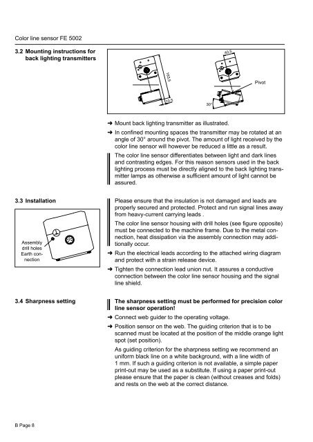
3.2 Mounting instructions for<br />
back lighting transmitters<br />
3.3 Installation<br />
Assembly<br />
drill holes<br />
Earth connection<br />
3.4 Sharpness setting<br />
B Page 8<br />
Mount back lighting transmitter as illustrated.<br />
In confined mounting spaces the transmitter may be rotated at an<br />
angle of 30° around the pivot. The amount of light received by the<br />
color <strong>line</strong> s<strong>en</strong>sor will however be reduced a little as a result.<br />
The color <strong>line</strong> s<strong>en</strong>sor differ<strong>en</strong>tiates betwe<strong>en</strong> light and dark <strong>line</strong>s<br />
and contrasting edges. For this reason s<strong>en</strong>sors used in the back<br />
lighting process must be directly aligned to the back lighting transmitter<br />
lamps as otherwise a suffici<strong>en</strong>t amount of light cannot be<br />
assured.<br />
Please <strong>en</strong>sure that the insulation is not damaged and leads are<br />
properly secured and protected. Protect and run signal <strong>line</strong>s away<br />
from heavy-curr<strong>en</strong>t carrying leads .<br />
The color <strong>line</strong> s<strong>en</strong>sor housing with drill holes (see figure opposite)<br />
must be connected to the machine frame. Due to the metal connection,<br />
heat dissipation via the assembly connection may additionally<br />
occur.<br />
Run the electrical leads according to the attached wiring diagram<br />
and protect with a strain release device.<br />
Tight<strong>en</strong> the connection lead union nut. It assures a conductive<br />
connection betwe<strong>en</strong> the color <strong>line</strong> s<strong>en</strong>sor housing and the signal<br />
<strong>line</strong> shield.<br />
The sharpness setting must be performed for precision color<br />
<strong>line</strong> s<strong>en</strong>sor operation!<br />
Connect web guider to the operating voltage.<br />
Pivot<br />
Position s<strong>en</strong>sor on the web. The guiding criterion that is to be<br />
scanned must be located at the position of the middle orange light<br />
spot (set position).<br />
As guiding criterion for the sharpness setting we recomm<strong>en</strong>d an<br />
uniform black <strong>line</strong> on a white background, with a <strong>line</strong> width of<br />
1 mm. If such a guiding criterion is not available, a simple paper<br />
print-out may be used as a substitute. If using a paper print-out<br />
please <strong>en</strong>sure that the paper is clean (without creases and folds)<br />
and rests on the web at the correct distance.