Ingineria Iluminatului - Journal of Lighting Engineering - Prof. Florin ...
Ingineria Iluminatului - Journal of Lighting Engineering - Prof. Florin ...
Ingineria Iluminatului - Journal of Lighting Engineering - Prof. Florin ...
Create successful ePaper yourself
Turn your PDF publications into a flip-book with our unique Google optimized e-Paper software.
⎛ i ⎞<br />
d ⎜ ⎟ ⎛<br />
i u<br />
2 ⎞<br />
⎝u⎠ =<br />
⎜<br />
1<br />
⎟<br />
dt τ u ⎜<br />
−<br />
u<br />
2 ⎟<br />
⎜<br />
pk<br />
⎟<br />
⎝ ⎠<br />
(2)<br />
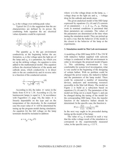
upk is the voltage over-striking peak value.<br />
Typical for (2) is the suggestion that the arc<br />
characteristics are defined by its power. By<br />
combining both equation the arc electrical<br />
values dynamics could be expressed:<br />
⎛ i ⎞<br />
d ⎜ ⎟<br />
⎜u⎟ ⎛<br />
u<br />
2<br />
d i u i<br />
⎞<br />
⎝ ⎠<br />
g<br />
=<br />
⎜ d d 1<br />
⎟ 0<br />
dt τ u ⎜<br />
+ −<br />
u<br />
2 P ⎟<br />
+<br />
τ<br />
d ⎜<br />
pk 0 ⎟<br />
⎝ ⎠<br />
(3)<br />
The quantity g0 is the gas environment<br />
conductivity at the beginning before the arc<br />
formation, ud is the voltage upon the light arc <strong>of</strong><br />
the lamp and upk is a parameter, by which you<br />
set up the striking voltage. An equation is extra<br />
added to the mathematical model. This equation<br />
reflects the electrical behavior <strong>of</strong> the anode and<br />
cathode areas, which conductivity is in direct<br />
ratio to the arc conductivity and in reverse ratio<br />
to a function <strong>of</strong> the conducted current.<br />
i i (4)<br />
=<br />
n<br />
+ g<br />
u 0<br />
a u ( α i + β<br />
d )<br />
According to [6], the index n varies in the<br />
limits from 0.34 to 1.38. According to [3], for<br />
luminescent lamps is equal to 2. In accordance<br />
with Fugenfirov [7, page 10], the index n is<br />
linearly dependable on the type and on the<br />
temperature <strong>of</strong> the electrodes. In the examined<br />
case the exact value <strong>of</strong> n will be determined by<br />
tuning up the program model during simulation.<br />
An equation for the full voltage on the lamp<br />
terminals should be included in addition<br />
u = u + u<br />
d a ,(5)<br />
where: u is the voltage drops on the lamp, ud -<br />
voltage drop on the light arc and ua - voltage<br />
drop for the cathode and anode areas.<br />
The given analytical model <strong>of</strong> the HID lamp<br />
expressed by equations (3), (4) and (5) consists<br />
<strong>of</strong> six parameters – τ, α, β, upk, P0, g0. During<br />
work in nominal conditions is presumed that<br />
these parameters are constants. The values <strong>of</strong><br />
the parameters are determined at the time when<br />
tuning the simulation model. They are picked up<br />
in such a way that the behavior <strong>of</strong> the model is<br />
the closest to the behavior <strong>of</strong> the lamp at the<br />
experiments.<br />
3. Simulation model in Mat Lab environment<br />
A modeling <strong>of</strong> the HID lamp SON-T Pro 250 W<br />
with inductive ballast supplied with network<br />
voltage is conducted in Mat lab environment in<br />
order to investigate the proposed model (Figure<br />
1). This calculating environment is very<br />
comfortable for system level investigation, what<br />
is very useful in the beginning <strong>of</strong> the designing<br />
<strong>of</strong> certain ballast. With no problem could be<br />
changed the power source, the inductive ballast<br />
and the parameters <strong>of</strong> the lamp model. There<br />
could be connected a number <strong>of</strong> measuring<br />
devices, analyzers and monitoring resources<br />
accessible in the Mat Lab library. The model on<br />
Figure 2 is build as a subsystem based on<br />
equations (3), (4) and (5). The parameters <strong>of</strong> the<br />
model are bring out in a mask Figure 3, and can<br />
be changed during the tuning <strong>of</strong> the model for<br />
the corresponding HID lamp. First, the transfer<br />
function <strong>of</strong> the inductive ballast should be<br />
determined. In the specific case, the function is<br />
Is () 1<br />
W() s = = (6)<br />
Us () 0.196s+ 1<br />
In the next way ought to be proceeded during<br />
tuning up the model <strong>of</strong> the lamp:<br />
The value <strong>of</strong> upk is selected in such a way<br />
that the strike voltage result <strong>of</strong> the simulation to<br />
correspond to the experimentally measured<br />
value, in the specific case upk=115 V.<br />
INGINERIA ILUMINATULUI 15-2005 29


