ch03 IP Addressing.pdf - The Cisco Learning Network
ch03 IP Addressing.pdf - The Cisco Learning Network
ch03 IP Addressing.pdf - The Cisco Learning Network
Create successful ePaper yourself
Turn your PDF publications into a flip-book with our unique Google optimized e-Paper software.
12 Chapter 3: <strong>IP</strong> <strong>Addressing</strong><br />
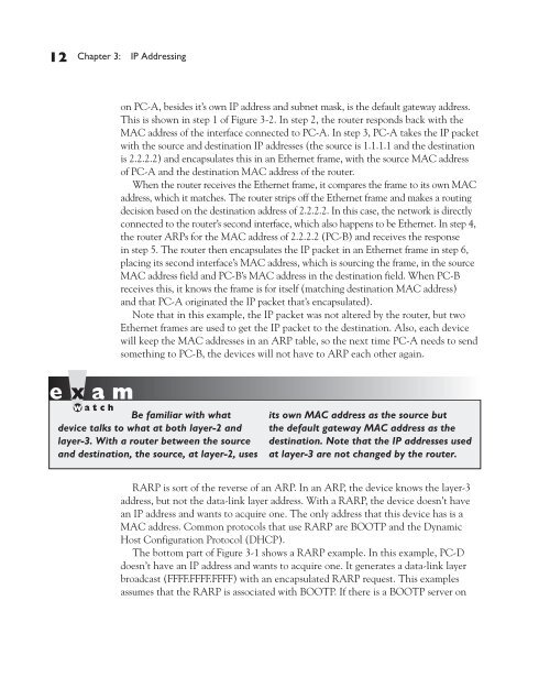
on PC-A, besides it’s own <strong>IP</strong> address and subnet mask, is the default gateway address.<br />
This is shown in step 1 of Figure 3-2. In step 2, the router responds back with the<br />
MAC address of the interface connected to PC-A. In step 3, PC-A takes the <strong>IP</strong> packet<br />
with the source and destination <strong>IP</strong> addresses (the source is 1.1.1.1 and the destination<br />
is 2.2.2.2) and encapsulates this in an Ethernet frame, with the source MAC address<br />
of PC-A and the destination MAC address of the router.<br />
When the router receives the Ethernet frame, it compares the frame to its own MAC<br />
address, which it matches. <strong>The</strong> router strips off the Ethernet frame and makes a routing<br />
decision based on the destination address of 2.2.2.2. In this case, the network is directly<br />
connected to the router’s second interface, which also happens to be Ethernet. In step 4,<br />
the router ARPs for the MAC address of 2.2.2.2 (PC-B) and receives the response<br />
in step 5. <strong>The</strong> router then encapsulates the <strong>IP</strong> packet in an Ethernet frame in step 6,<br />
placing its second interface’s MAC address, which is sourcing the frame, in the source<br />
MAC address field and PC-B’s MAC address in the destination field. When PC-B<br />
receives this, it knows the frame is for itself (matching destination MAC address)<br />
and that PC-A originated the <strong>IP</strong> packet that’s encapsulated).<br />
Note that in this example, the <strong>IP</strong> packet was not altered by the router, but two<br />
Ethernet frames are used to get the <strong>IP</strong> packet to the destination. Also, each device<br />
will keep the MAC addresses in an ARP table, so the next time PC-A needs to send<br />
something to PC-B, the devices will not have to ARP each other again.<br />
Be familiar with what<br />
device talks to what at both layer-2 and<br />
layer-3. With a router between the source<br />
and destination, the source, at layer-2, uses<br />
its own MAC address as the source but<br />
the default gateway MAC address as the<br />
destination. Note that the <strong>IP</strong> addresses used<br />
at layer-3 are not changed by the router.<br />
RARP is sort of the reverse of an ARP. In an ARP, the device knows the layer-3<br />
address, but not the data-link layer address. With a RARP, the device doesn’t have<br />
an <strong>IP</strong> address and wants to acquire one. <strong>The</strong> only address that this device has is a<br />
MAC address. Common protocols that use RARP are BOOTP and the Dynamic<br />
Host Configuration Protocol (DHCP).<br />
<strong>The</strong> bottom part of Figure 3-1 shows a RARP example. In this example, PC-D<br />
doesn’t have an <strong>IP</strong> address and wants to acquire one. It generates a data-link layer<br />
broadcast (FFFF.FFFF.FFFF) with an encapsulated RARP request. This examples<br />
assumes that the RARP is associated with BOOTP. If there is a BOOTP server on


