JJP-8BT 8" Jointer-Planer - Rockler.com
JJP-8BT 8" Jointer-Planer - Rockler.com
JJP-8BT 8" Jointer-Planer - Rockler.com
Create successful ePaper yourself
Turn your PDF publications into a flip-book with our unique Google optimized e-Paper software.
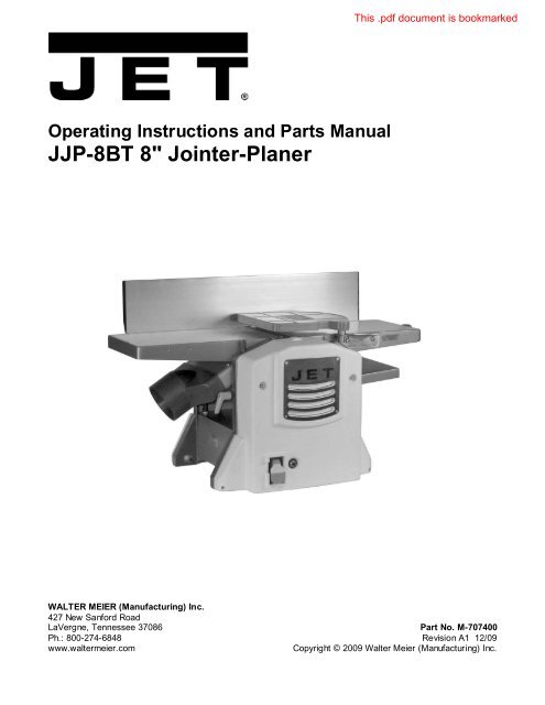
Operating Instructions and Parts Manual<br />
<strong>JJP</strong>-<strong>8BT</strong> 8" <strong>Jointer</strong>-<strong>Planer</strong><br />
WALTER MEIER (Manufacturing) Inc.<br />
427 New Sanford Road<br />
LaVergne, Tennessee 37086 Part No. M-707400<br />
Ph.: 800-274-6848 Revision A1 12/09<br />
www.waltermeier.<strong>com</strong> Copyright © 2009 Walter Meier (Manufacturing) Inc.
Warranty and Service<br />
Walter Meier (Manufacturing) Inc., warrants every product it sells. If one of our tools needs service or repair, one of our<br />
Authorized Service Centers located throughout the United States can give you quick service. In most cases, any of these<br />
Walter Meier Authorized Service Centers can authorize warranty repair, assist you in obtaining parts, or perform routine<br />
maintenance and major repair on your JET® tools. For the name of an Authorized Service Center in your area call<br />
1-800-274-6848.<br />
MORE INFORMATION<br />
Walter Meier is consistently adding new products to the line. For <strong>com</strong>plete, up-to-date product information, check with<br />
your local Walter Meier distributor, or visit waltermeier.<strong>com</strong>.<br />
WARRANTY<br />
JET products carry a limited warranty which varies in duration based upon the product (MW stands for Metalworking, WW<br />
stands for Woodworking).<br />
WHAT IS COVERED?<br />
This warranty covers any defects in workmanship or materials subject to the exceptions stated below. Cutting tools,<br />
abrasives and other consumables are excluded from warranty coverage.<br />
WHO IS COVERED?<br />
This warranty covers only the initial purchaser of the product.<br />
WHAT IS THE PERIOD OF COVERAGE?<br />
The general JET warranty lasts for the time period specified in the product literature of each product.<br />
WHAT IS NOT COVERED?<br />
Three Year, Five Year and Lifetime Warranties do not cover products used for industrial or educational purposes.<br />
Products with Three Year, Five Year or Lifetime Warranties that are used for industrial or education purposes revert to a<br />
One Year Warranty. This warranty does not cover defects due directly or indirectly to misuse, abuse, negligence or<br />
accidents, normal wear-and-tear, improper repair or alterations, or lack of maintenance.<br />
HOW TO GET SERVICE<br />
The product or part must be returned for examination, postage prepaid, to a location designated by us. For the name of<br />
the location nearest you, please call 1-800-274-6848.<br />
You must provide proof of initial purchase date and an explanation of the <strong>com</strong>plaint must ac<strong>com</strong>pany the merchandise. If<br />
our inspection discloses a defect, we will repair or replace the product, or refund the purchase price, at our option. We will<br />
return the repaired product or replacement at our expense unless it is determined by us that there is no defect, or that the<br />
defect resulted from causes not within the scope of our warranty in which case we will, at your direction, dispose of or<br />
return the product. In the event you choose to have the product returned, you will be responsible for the shipping and<br />
handling costs of the return.<br />
HOW STATE LAW APPLIES<br />
This warranty gives you specific legal rights; you may also have other rights which vary from state to state.<br />
LIMITATIONS ON THIS WARRANTY<br />
WALTER MEIER (MANUFACTURING) INC., LIMITS ALL IMPLIED WARRANTIES TO THE PERIOD OF THE LIMITED<br />
WARRANTY FOR EACH PRODUCT. EXCEPT AS STATED HEREIN, ANY IMPLIED WARRANTIES OR<br />
MERCHANTABILITY AND FITNESS ARE EXCLUDED. SOME STATES DO NOT ALLOW LIMITATIONS ON HOW<br />
LONG THE IMPLIED WARRANTY LASTS, SO THE ABOVE LIMITATION MAY NOT APPLY TO YOU.<br />
WALTER MEIER SHALL IN NO EVENT BE LIABLE FOR DEATH, INJURIES TO PERSONS OR PROPERTY, OR FOR<br />
INCIDENTAL, CONTINGENT, SPECIAL, OR CONSEQUENTIAL DAMAGES ARISING FROM THE USE OF OUR<br />
PRODUCTS. SOME STATES DO NOT ALLOW THE EXCLUSION OR LIMITATION OF INCIDENTAL OR<br />
CONSEQUENTIAL DAMAGES, SO THE ABOVE LIMITATION OR EXCLUSION MAY NOT APPLY TO YOU.<br />
Walter Meier sells through distributors only. The specifications in Walter Meier catalogs are given as general information<br />
and are not binding. Members of Walter Meier reserve the right to effect at any time, without prior notice, those alterations<br />
to parts, fittings, and accessory equipment which they may deem necessary for any reason whatsoever. JET® branded<br />
products are not sold in Canada by Walter Meier.<br />
2
Table of Contents<br />
Warranty and Service................................................................................................................................2<br />
Table of Contents .....................................................................................................................................3<br />
Warnings..................................................................................................................................................4<br />
Features ..................................................................................................................................................7<br />
Specifications ...........................................................................................................................................7<br />
Optional Accessories ................................................................................................................................7<br />
Unpacking ................................................................................................................................................8<br />
Stand .......................................................................................................................................................9<br />
Assembly ............................................................................................................................................... 10<br />
<strong>Jointer</strong> Setup .......................................................................................................................................... 12<br />
<strong>Planer</strong> Setup .......................................................................................................................................... 12<br />
Operating Controls.................................................................................................................................. 13<br />
Adjustments ........................................................................................................................................... 15<br />
Basic Operations .................................................................................................................................... 18<br />
Maintenance .......................................................................................................................................... 22<br />
Lubrication ............................................................................................................................................. 22<br />
Troubleshooting ...................................................................................................................................... 23<br />
Parts ...................................................................................................................................................... 26<br />
Electrical Connection .............................................................................................................................. 40<br />
The specifications in this manual are given as general information and are not binding. Walter Meier<br />
(Manufacturing) Inc., reserves the right to effect, at any time and without prior notice, changes or alterations to<br />
parts, fittings, and accessory equipment deemed necessary for any reason whatsoever.<br />
3
Warnings<br />
1. Read and understand the entire owner's manual before attempting assembly or operation.<br />
2. Read and understand the warnings posted on the machine and in this manual. Failure to <strong>com</strong>ply with<br />
all of these warnings may cause serious injury.<br />
3. Replace the warning labels if they be<strong>com</strong>e obscured or removed.<br />
4. This Woodworking <strong>Jointer</strong>-planer is designed and intended for use by properly trained and<br />
experienced personnel only. If you are not familiar with the proper and safe operation of a<br />
woodworking jointer or planer, do not use until proper training and knowledge have been obtained.<br />
5. Do not use this for other than its intended use. If used for other purposes, Walter Meier<br />
(Manufacturing) Inc., disclaims any real or implied warranty and holds itself harmless from any injury<br />
that may result from that use.<br />
6. Always wear approved safety glasses/face shields while using this woodworking jointer-planer.<br />
Everyday eyeglasses only have impact resistant lenses; they are not safety glasses.<br />
7. Before operating this woodworking jointer-planer, remove tie, rings, watches and other jewelry, and<br />
roll sleeves up past the elbows. Remove all loose clothing and confine long hair. Non-slip footwear or<br />
anti-skid floor strips are re<strong>com</strong>mended. Do not wear gloves.<br />
8. Wear ear protectors (plugs or muffs) during extended periods of operation.<br />
9. Some dust created by power sanding, sawing, grinding, drilling and other construction activities<br />
contain chemicals known to cause cancer, birth defects or other reproductive harm. Some examples<br />
of these chemicals are:<br />
• Lead from lead based paint.<br />
• Crystalline silica from bricks, cement and other masonry products.<br />
• Arsenic and chromium from chemically treated lumber.<br />
Your risk of exposure varies, depending on how often you do this type of work. To reduce your<br />
exposure to these chemicals, work in a well-ventilated area and work with approved safety<br />
equipment, such as face or dust masks that are specifically designed to filter out microscopic<br />
particles.<br />
10. Do not operate this machine while tired or under the influence of drugs, alcohol or any medication.<br />
11. Make certain the switch is in the OFF position before connecting the machine to the power source.<br />
12. Make certain the machine is properly grounded.<br />
13. Make all machine adjustments or maintenance with the machine unplugged from the power source.<br />
14. Remove adjusting keys and wrenches. Form a habit of checking to see that keys and adjusting<br />
wrenches are removed from the machine before turning it on.<br />
15. Keep safety guards in place at all times when the machine is in use. If removed for maintenance<br />
purposes, use extreme caution and replace the guards immediately.<br />
16. Make sure the woodworking jointer-planer is firmly secured to the floor or bench before use.<br />
17. Check damaged parts. Before further use of the machine, a guard or other part that is damaged<br />
should be carefully checked to determine that it will operate properly and perform its intended<br />
function. Check for alignment of moving parts, binding of moving parts, breakage of parts, mounting<br />
and any other conditions that may affect its operation. A guard or other part that is damaged should<br />
be properly repaired or replaced.<br />
18. Provide for adequate space surrounding work area and non-glare, overhead lighting.<br />
19. Keep the floor around the machine clean and free of scrap material, oil and grease.<br />
4
20. Keep visitors a safe distance from the work area. Keep children away.<br />
21. Make your workshop child proof with padlocks, master switches or by removing starter keys.<br />
22. Give your work undivided attention. Looking around, carrying on a conversation and “horse-play” are<br />
careless acts that can result in serious injury.<br />
23. Maintain a balanced stance at all times so that you do not fall or lean against the cutterhead or other<br />
moving parts. Do not overreach or use excessive force to perform any machine operation.<br />
24. Use the right tool at the correct speed and feed rate. Do not force a tool or attachment to do a job for<br />
which it was not designed. The right tool will do the job better and safer.<br />
25. Use re<strong>com</strong>mended accessories; improper accessories may be hazardous.<br />
26. Maintain tools with care. Keep knives sharp and clean for the best and safest performance. Follow<br />
instructions for lubricating and changing accessories.<br />
27. Turn off the machine before cleaning. Use a brush or <strong>com</strong>pressed air to remove chips or debris — do<br />
not use your hands.<br />
28. Do not stand on the machine. Serious injury could occur if the machine tips over.<br />
29. Never leave the machine running unattended. Turn the power off and do not leave the machine until it<br />
<strong>com</strong>es to a <strong>com</strong>plete stop.<br />
30. Before turning on machine, remove all extra equipment such as keys, wrenches, scrap, stock, and<br />
cleaning rags away from the machine.<br />
31. Always use a hold-down or push block when surfacing stock less than 12" inches long, or 3 inches<br />
wide, or 3 inches thick.<br />
32. Do not perform jointing operations on material shorter than 8", narrower than 3/4" or less than 1/4"<br />
thick.<br />
33. The hands must never be closer than 3 inches to<br />
the cutterhead (see Figure).<br />
34. Never apply pressure to stock directly over the<br />
cutterhead. This may result in the stock tipping<br />
into the cutterhead along with the operator's<br />
fingers. Position hands away from extreme ends<br />
of stock, and push through with a smooth, even<br />
motion. Never back workpiece toward the infeed<br />
table.<br />
35. To avoid kickback, the grain must run in the<br />
same direction you are cutting. Before<br />
attempting to joint, or plane, each work piece<br />
must be carefully examined for stock condition<br />
and grain orientation.<br />
5
36. When working with a swirl grain wood or burls, making it necessary to plane against the grain, use a<br />
lesser depth of cut and a slow rate of feed.<br />
37. Move the hands in an alternate motion from back to front as the work continues through the cut.<br />
Never pass the hands directly over the cutter knife. As one hand approaches the knives remove it<br />
from the stock in an arc motion and place it back on the stock in a position beyond the cutter knife<br />
(Fig. 2).<br />
38. At all times hold the stock firmly.<br />
39. Do not use this for other than it intended use. If used for other purposes, Walter Meier<br />
(Manufacturing) Inc.disclaims any real or implied warranty and holds itself harmless for any injury or<br />
damage which may result from that use.<br />
Familiarize yourself with the following safety notices used in this manual:<br />
This means that if precautions are not heeded, it may result in minor injury and/or<br />
possible machine damage.<br />
even death.<br />
This means that if precautions are not heeded, it may result in serious injury or possibly<br />
- - SAVE THESE INSTRUCTIONS - -<br />
Read and understand the entire contents of this manual before attempting<br />
assembly or operation! Failure to <strong>com</strong>ply may cause serious injury!<br />
6
Features<br />
Specifications<br />
Features<br />
Model number ......................................................................................................................... <strong>JJP</strong>-<strong>8BT</strong><br />
Stock number ........................................................................................................................... 707400<br />
Cutterhead speed ................................................................................................................... 9000rpm<br />
Number of knives................................................................................................................................ 2<br />
Cutter knife length........................................................................................................................ 8-1/4"<br />
Cutter knife thickness .................................................................................................................. 0.060"<br />
Dust port diameter ............................................................................................................... 2-1/2" or 4”<br />
<strong>Jointer</strong> table ........................................................................................................................ 29"x 8-1/4”<br />
Max stock removal .......................................................................................................................... 1/8”<br />
Max cutting width ...............................................................................................................................8"<br />
Fence ................................................................................................................................ 4-1/8" x 21”<br />
Fence tilt .............................................................................................................................. 90°- 45° R<br />
Fence positive stop ................................................................................................................ 90°, 45°R<br />
<strong>Planer</strong> table ...................................................................................................................10-5/8" x 8-1/2"<br />
<strong>Planer</strong> capacity<br />
Maximum cutting thickness ........................................................................................................ 4-1/2"<br />
Max depth of cut ........................................................................................................................... 5/64”<br />
Min length of work piece.....................................................................................................................6"<br />
Feed rate ................................................................................................................................19.5 fpm<br />
Motor<br />
Voltage ................................................................................................................... 120V, 60Hz, 13A<br />
Switch ...................................................................................... Toggle switch with overload protection<br />
Overall Dimensions (LxWxH) ............................................................................... 31" x 16-1/2" x 18-1/2"<br />
Net weight ................................................................................................................................... 58 lbs<br />
Optional Accessories<br />
Stock No. Description<br />
707401 8" <strong>Jointer</strong>/<strong>Planer</strong> Blades<br />
707402 8" <strong>Jointer</strong> <strong>Planer</strong> Stand<br />
7
Unpacking<br />
Remove all contents from the shipping carton.<br />
Do not discard the carton or packing material<br />
until your Model <strong>JJP</strong>-<strong>8BT</strong> <strong>Jointer</strong>-<strong>Planer</strong> is<br />
assembled and is running satisfactorily.<br />
Compare the contents of the carton against the<br />
list of parts in Contents of Shipping Container<br />
(below). The letter identification in the list<br />
corresponds to the items shown at right. This is<br />
your key for identifying the parts used<br />
throughout the Assembly section for easy<br />
reference.<br />
Remove the protective coating that is applied to<br />
the table with a house hold grease and spot<br />
remover.<br />
Contents of the Main Carton<br />
01 <strong>Jointer</strong> Fence (A)<br />
01 Dust Chute (B)<br />
01 Cutterhead Guard (C)<br />
01 <strong>Jointer</strong>-<strong>Planer</strong> (D)<br />
01 2-1/2" to 4" Hose Adapter (E)<br />
01 <strong>Planer</strong> Outfeed Table Extension (F)<br />
01 Owner's Manual (G)<br />
02 Push Block (H)<br />
Figure 1 – Contents of the Main Carton<br />
8<br />
Knobs and Handles<br />
01 Lock Knob (J)<br />
01 Lock Knob (K)<br />
01 Height Adjust Handle (L)<br />
01 Flat Washer (M)<br />
01 Lock Handle (N)<br />
Figure 2 – Knobs and Handles<br />
Hardware<br />
02 Pan Head Machine Screw (O)<br />
02 Hex Nut (P)<br />
02 Socket Head Cap Screw (Q)<br />
03 Socket Head Cap Screw (R)<br />
05 Lock Washer (S)<br />
06 Flat Washer (T)<br />
03 Hex Nut (U)<br />
Figure 3 – Hardware<br />
Tools Included<br />
01 Knife Setting Gauge (V)<br />
01 3, 5, 6mm hex wrenches (set of 3) (W)<br />
01 8/10mm Open-end Wrench (X)<br />
Figure 4 – Tools Included
Stand<br />
The stand is not included but is an optional item<br />
available for purchase. To purchase, call Customer<br />
Service at the phone number on the cover of this<br />
manual. The following instructions are included if<br />
you have purchased the stand or will purchase one<br />
at a later date.<br />
Compare the contents of the carton against the list<br />
of parts in Contents of Stand Carton (below).<br />
Contents of Stand Carton<br />
02 Long Support Plate(SA)<br />
02 Short Support Plate (SB)<br />
02 Long Stand Top Support (SC)<br />
02 Short Stand Top Support (SD)<br />
04 Stand Leg (SE)<br />
Stand Hardware<br />
04 Hex Cap Screw (SF)<br />
24 Carriage Bolt (SG)<br />
28 Flat Washer (SH)<br />
24 Lock Washer (SJ)<br />
28 Hex Nut (SK)<br />
04 Socket Head Cap Screw (SM)<br />
04 Flat Washer (SN)<br />
04 Lock Washer (SP)<br />
04 Rubber Foot (SQ)<br />
9<br />
Figure 5 – Contents of Stand Carton<br />
Figure 6 – Stand Hardware
Assembly<br />
For assembly convenience, the item letter<br />
designators used throughout the Assembly section<br />
are the same as those used to identify shipping<br />
content and hardware <strong>com</strong>ponents on pages 8–9.<br />
Stand Assembly<br />
Note: If you do not plan to use a standat this time,<br />
skip this page and proceed to <strong>Jointer</strong>-<strong>Planer</strong><br />
Assembly on the following page.<br />
Referring to Figure 7:<br />
1. Select two legs (SE), one short stand top<br />
support (SD) and one short support plate (SB).<br />
2. Attach one end of the stand top support (SD) to<br />
the top of the first leg with two carriage bolts<br />
(SG), flat washers (SH), lock washers (SJ) and<br />
hex nuts (SK). Attach the other end of the<br />
stand top support (SD) to the second leg in the<br />
same manner. Hand-tighten only at this time.<br />
3. Attach a support plate (SB) to each leg (SE) in<br />
the same manner with two carriage bolts (SG),<br />
flat washers (SH), lock washers (SJ) and hex<br />
nuts (SK). Hand-tighten only at this time.<br />
4. Repeat steps 1–3 using the remaining legs,<br />
short stand top support and support plate.<br />
5. Complete the stand construction by attaching<br />
long stand top supports (SE) and long support<br />
plates (SA) to the leg assemblies constructed<br />
in steps 1–4. Hand-tighten all hardware only at<br />
this time.<br />
6. Place a rubber foot (SQ) on a hex cap screw<br />
(SF), then insert the threaded end of the screw<br />
through the opening on the bottom of the leg.<br />
7. Secure with flat washer (SH) and hex nut (SK).<br />
8. Attach rubber feet to remaining legs in the<br />
same manner.<br />
9. Place stand upright. Ensure that the stand is<br />
on a level surface and all four legs are<br />
contacting the surface.<br />
10. Tighten all hex nuts with the 10mm<br />
wrench (U, Fig. 4) provided.<br />
Mounting <strong>Jointer</strong>-<strong>Planer</strong> to Stand<br />
Referring to Figure 8:<br />
1. Place the <strong>Jointer</strong>-<strong>Planer</strong> (D) onto the assembled<br />
stand and secure with 4 socket head cap<br />
screws (SM), lock washers (SP), and flat<br />
washers (SN).<br />
2. Tighten all socket head cap screws (SM) with<br />
the 5mm hex wrench (W, Fig. 4) provided.<br />
10<br />
SK<br />
SK<br />
SJ SH<br />
SJ<br />
SA<br />
SH<br />
SD<br />
SC<br />
SB<br />
SE<br />
SK<br />
SH<br />
SQ<br />
Figure 7<br />
Figure 8<br />
SF<br />
SG<br />
SG
<strong>Jointer</strong>-<strong>Planer</strong> Assembly<br />
Referring to Figure 9:<br />
Fence<br />
1. Attach jointer fence (A) to back of jointer<br />
outfeed table (D3) with two each socket head<br />
cap screws (Q) and lock washers (S). Tighten<br />
screws with 5mm hex wrench (provided).<br />
Lock Knobs<br />
The <strong>JJP</strong>-<strong>8BT</strong> <strong>Jointer</strong>-<strong>Planer</strong> <strong>com</strong>es equipped with<br />
two lock knobs to secure the position of the jointer<br />
infeed table.<br />
2. Install jointer infeed table lock knobs (K, T).<br />
Note: The shaft length of each lock knob (refer<br />
to Figure 2) are different. Be sure to install<br />
each in the correct location.<br />
Extension Table<br />
3. Attach the planer outfeed extension table (F) to<br />
the planer table (D5) with three socket head cap<br />
screws (R), six flat washers (T), three lock<br />
washers (S) and three hex nuts (U).<br />
Screws (R) and flat washers T1 are inserted<br />
through the extension table (F) and planer<br />
table (D5), then fastened from inside the planer<br />
table (D5) with flat washers (T2), lock washers<br />
(S) and hex nuts (U).<br />
4. Tighten screws with 5mm hex wrench and<br />
10mm open end wrench.<br />
Extension Table Adjustment<br />
Two setscrews located underneath the extension<br />
table (F) are used to adjust the height position of<br />
the outer (protruding) edge, which must be slightly<br />
higher than the main table (D5) in order to minimize<br />
snipe (see Avoiding Snipe on page 21).<br />
5. Using a 4mm hex wrench (provided), turn<br />
setscrews slightly clockwise to raise the table<br />
or counterclockwise to lower the table.<br />
Lock Handle<br />
Referring to Figure 10:<br />
Attach planer table lock handle (N) and flat washer (M).<br />
Cutterhead Guard<br />
6. Install cutterhead guard (C) by securing the<br />
bracket (C1) to the side of the jointer infeed<br />
table (D5) with two each pan head machine<br />
screws (O) and hex nuts (P).<br />
11<br />
Figure 9<br />
Important: It is extremely important that spring<br />
action causes the cutterguard (C) to retract against<br />
the fence (A), concealing the cutterhead (A1). If<br />
spring return tension is not enough, adjust the<br />
spring located on the cutterhead pivot shaft<br />
accordingly.<br />
Figure 10
<strong>Jointer</strong> Setup<br />
Disconnect machine from<br />
power source before making any adjustments.<br />
Failure to <strong>com</strong>ply may cause serious injury.<br />
Referring to Figure 11:<br />
1. Loosen lock handle (N).<br />
2. Install planer table height adjustment handle (L).<br />
3. Turn handle (L) counterclockwise and lower<br />
planer table (D1) all the way.<br />
4. Remove hex nut (B1) and flat washer (B2) from<br />
dust chute (B).<br />
5. Orient the dust chute (B) as shown and install<br />
into the infeed opening.<br />
Position the chute (B) such that the two<br />
positioning keys and one threaded positioning<br />
screw underneath the chute meshes with three<br />
positioning holes on the table (D1).<br />
6. Raise the table (turn handle L clockwise) until<br />
the dust chute (B) is held firmly in place<br />
between the planer infeed table (D1) and<br />
jointer outfeet table (D2). Do not overtighten.<br />
7. Tighten lock handle (L).<br />
Step 8 is optional.<br />
8. Further secure the dust chute by reinstalling<br />
the hex nut (B1) and flat washer (B2) from<br />
underneath the planer infeed table (D1).<br />
9. Remove handle (L).<br />
<strong>Planer</strong> Setup<br />
If the machine is currently set up for jointer<br />
operation, remove the dust chute (B, Fig. 11).<br />
Refer to the <strong>Jointer</strong> Setup section above.<br />
Referring to Figure 12:<br />
1. Swing cutterguard (C) away from fence (A),<br />
which will expose the cutterhead.<br />
Cutterhead knives are<br />
dangerously sharp. Use extreme caution when<br />
working around them. Failure to <strong>com</strong>ply may<br />
cause serious injury.<br />
2. Orient the dust chute (B) as shown. Install onto<br />
the jointer outfeed table (D2) and secure by<br />
tightening lock knobs (B4).<br />
12<br />
Figure 11<br />
Important: Dust chute (B) must be properly<br />
installed in both <strong>Jointer</strong> setup and <strong>Planer</strong> setup. If<br />
improper installation fails to activate a microswitch,<br />
the machine will not start.<br />
Figure 12
Operating Controls<br />
Disconnect machine from<br />
power source before making any adjustments.<br />
Failure to <strong>com</strong>ply may cause serious injury.<br />
Power<br />
Plug power cord into outlet.<br />
Referring to Figure 13:<br />
Start/Stop<br />
Pull the red switch (A) out to start. Push in to stop.<br />
Safety Key<br />
Removing the safety key (B) will render the<br />
start/stop switch inoperable. The machine can<br />
continue to operate without the key, but upon<br />
stopping cannot be restarted until it is reinstalled.<br />
Reset Switch<br />
If the machine should <strong>com</strong>e to an unexpected stop<br />
during operation due to overload or jammed workpiece,<br />
etc.:<br />
1. Set the start/stop switch (A) set to stop<br />
(pushed in).<br />
2. Momentarily press, then release the reset<br />
switch (C).<br />
3. Restart machine.<br />
<strong>Planer</strong> Controls and Adjustments<br />
Referring to Figure 14:<br />
Table Lock<br />
Turn the lock handle (A) counterclockwise to<br />
release and permit table adjustment. Turn the lock<br />
handle (A) clockwise to secure the planer table (D)<br />
in its selected position.<br />
Table Height Adjustment<br />
The planer table height is set as follows:<br />
1. Unlock the table lock (A).<br />
2. Install the removeable adjustment handle (C)<br />
onto the shaft (B).<br />
3. Rotate the adjustment handle (C) clockwise to<br />
raise the planer table (D), counterclockwise to<br />
lower.<br />
Each revolution of the adjustment handle (C) results<br />
in a 3/32" up or down movement of the table (D). A<br />
scale indicates the amount of table travel. The<br />
pointer (E) indicates the table position on the scale<br />
relative to the cutterhead.<br />
13<br />
Figure 13<br />
Figure 14
<strong>Jointer</strong> Controls and Adjustments<br />
Refer to Figure 15.<br />
Infeed Table Height Adjustment<br />
Two lock knobs (F) and a height adjustment knob<br />
(E) control the height adjustment of the infeed<br />
table (D).<br />
To adjust:<br />
1. Loosen lock knobs (F).<br />
2. Turn the height adjustment knob (E) clockwise<br />
to raise the infeed table (D) or counterclockwise<br />
to lower the table.<br />
The amount of table adjustment can be read<br />
on the scale (C).<br />
3. Tighten the lock knobs (F).<br />
Note: A depth of cut of 1/16" or less is re<strong>com</strong>mended.<br />
Cutterhead Guard<br />
Properly positioned, the cutterhead guard (A)<br />
should rest against the fence (B1).<br />
Fence Bevel Adjustment<br />
The fence (B2) can be tilted backward (G) up to<br />
45° (that is, for a total included angle of 135° from<br />
table surface) as follows:<br />
1. Loosen lock handle (J).<br />
2. Tilt the fence (B2) back to the desired angle up<br />
to 135 degrees (G). Or you can place your<br />
beveled reference piece on the table and<br />
against the fence, adjusting the fence until the<br />
angle of the fence matches the bevel of your<br />
gauge piece.<br />
3. Tighten the lock handle (J).<br />
14<br />
Figure 15
Adjustments<br />
Cutterhead Knife Adjustment<br />
Cutterhead knives are<br />
dangerously sharp! Use extreme caution when<br />
inspecting, removing, sharpening or replacing<br />
knives into the cutterhead. Failure to <strong>com</strong>ply<br />
may cause serious injury!<br />
Determining if adjustment is necessary:<br />
1. Disconnect machine from the power source.<br />
2. Remove the cutterhead guard.<br />
Referring to Figures 16 and 17:<br />
Note: To rotate the cutterhead the cutterhead<br />
pulley must be turned. This requires removing the<br />
panel on the front of the cabinet for access.<br />
3. Rotate the cutterhead (E) until one knife is in<br />
the 12 o'clock position. The 12 o'clock position<br />
is the highest point a blade will reach in the<br />
cutting arc (C, Fig. 17).<br />
4. Place the knife setting gauge (J) on the<br />
outfeed table (F). One end of the gauge should<br />
be positioned over the cutting knife (C)<br />
towards the near the end of the blade (G).<br />
Use care when handling the knife<br />
setting gauge near the blades to prevent damage.<br />
Note the position of the knife blade with<br />
respect to the gauge, then move the gauge to<br />
the other side of the table towards the fence<br />
(H) and again note the position of the knife<br />
blade with respect to the gauge.<br />
The blade must be at the same height at each<br />
end and must also be at the same height as<br />
the outfeed table (bottom of gauge). If this is<br />
not the case, adjustment is required as follows:<br />
Adjustment procedure<br />
5. Slightly loosen six gib lock screws (A) by<br />
turning into the lock bar (B), clockwise as<br />
viewed from the infeed table (K).<br />
6. Adjust the blade height by turning jack screws<br />
(D) upon which the blade rests. To lower the<br />
blade, turn the screw clockwise. To raise, turn<br />
the screw counter-clockwise.<br />
7. When the blade is at the proper height,<br />
alternately tighten the six gib lock screws (A).<br />
Repeat steps 3 – 7 to adjust the remaining blade.<br />
Note: The most <strong>com</strong>mon cause for unsatisfactory<br />
cutting performance is improperly set knives. Many<br />
aftermarket devices are avaialable to further assist<br />
in the accurate setting of knives.<br />
15<br />
E<br />
D<br />
Figure 16<br />
C<br />
B<br />
Figure 17<br />
A
Replacing Cutter Knives<br />
Disconnect machine from<br />
power source before making any adjustments.<br />
Failure to <strong>com</strong>ply may cause serious injury.<br />
1. Disconnect machine from the power source.<br />
2. Remove the cutterhead guard.<br />
Cutterhead knives are<br />
dangerously sharp. Use extreme caution when<br />
inspecting, removing, sharpening, or replacing<br />
knives into the cutterhead. Failure to <strong>com</strong>ply<br />
may cause serious injury.<br />
Referring to Figures 16 and 17 (page 15):<br />
3. Turn all six gib lock screws (A) into the lock bar<br />
(B) by turning in a clockwise direction as<br />
viewed from the infeed table (K).<br />
4. Carefully remove the cutter knife (C) and lock<br />
bar (B).<br />
5. Repeat for the remaining knife.<br />
6. Thoroughly clean all surfaces of the<br />
cutterhead, knife slots and lock bars of any<br />
dust or debris.<br />
7. Insert the first replacement knife (C) into the<br />
knife slot, making sure it faces the proper<br />
direction.<br />
8. Insert lock bar (B) and tighten just enough to<br />
hold in place.<br />
9. Repeat for other the remaining blade.<br />
Following installation, the knives must be adjusted<br />
as described in Cutterhead Knive Adjustment on<br />
page 15.<br />
<strong>Jointer</strong> Fence Adjustment<br />
Referring to Figure 18:<br />
The jointer fence (A) can be adjusted from a full<br />
forward position (90º to table, corresponding to a<br />
scale reading of 0º) to a full back-tilted position of<br />
135 º (scale reading of 45 º).<br />
If setting to maximum positions do not stop the<br />
fence at 0º or 90º, make adjustments as follows:<br />
Fence 90º Adjustment<br />
1. Loosen lock handle (H) and bring fence fully<br />
forward. Using a square, determine if the fence<br />
is 90º to the table.<br />
If adjustment is required:<br />
2. Loosen jam nut (E) and adjust stop screw (D)<br />
in or out until a fence postion of 90º with<br />
respect to the table is achieved.<br />
3. Secure the jam nut (E).<br />
Check the scale indication. If the indicator (C) does<br />
not point to zero:<br />
4. Loosen screw (B), adjust accordingly, then<br />
retighten screw.<br />
Fence 45º Adjustment<br />
Verify that the fence and scale indication is<br />
accurate at 90º as outlined in Fence 90º<br />
Adjustment above.<br />
1. Loosen lock handle (H) and set the fence all<br />
the way back. Using a square, determine if the<br />
fence is 135º to the table.<br />
If adjustment is required:<br />
2. Loosen jam nut (G) and adjust stop screw (F)<br />
in or out until a fence postion of 135º with<br />
respect to the table is achieved. Note: The<br />
screw head stops against the fence mounting<br />
bracket.<br />
3. Secure the jam nut (G).<br />
16<br />
Figure 18
Belt Replacement<br />
Refer to Figure 19 when installing or replacing the<br />
the feed-roller (A) or cutterhead drive (D) belts.<br />
Disconnect machine from<br />
power source before making any adjustments.<br />
Failure to <strong>com</strong>ply may cause serious injury.<br />
Feed-roller Belt Replacement<br />
Cutterhead knives are<br />
dangerously sharp. Use extreme caution when<br />
replacing any belt. Contact with cutterhead<br />
knives will cause serious injury.<br />
1. Remove the front panel. This is the panel<br />
where the Start/Stop switch is located.<br />
2. Remove feed-roller belt (A) from pulley (B)<br />
while manually rotating pulley (C).<br />
When this is ac<strong>com</strong>plished, belt will fall away<br />
from pulley (C).<br />
3. Loop the new belt around pulley (C), then<br />
around pulley (B) while manually rotating<br />
pulley (C).<br />
4. When installed, continue to manually rotate<br />
pulley (C) and verify that belt is properly<br />
seated on both pulleys.<br />
5. Replace front cover.<br />
Cutterhead Drive Belt Replacement<br />
Cutterhead knives are<br />
dangerously sharp. Use extreme caution when<br />
replacing any belt. Contact with cutterhead<br />
knives will cause serious injury.<br />
The cutterhead drive belt should seldom if ever,<br />
require replacement. Follow the procedure below<br />
if, however, the belt should require replacement.<br />
1. Remove the feed-roller belt as described in<br />
Feed-roller Belt Replacement above.<br />
2. Remove the bottom portion of the cutterhead<br />
drive belt (D) from pulley (E) while manually<br />
rotating pulley (F).<br />
Use extreme caution to avoid<br />
contact with cutterhead knives while<br />
performing this step. Contact with cutterhead<br />
knives will cause serious injury.<br />
3. Remove top portion of belt (D) from pulley F,<br />
then work it under the chain and past pulley B<br />
to remove <strong>com</strong>pletely.<br />
17<br />
Figure 19<br />
4. Install new belt by first feeding the lower loop<br />
downward behind the gear (H) and pulley (C).<br />
This will properly position the lower loop of the<br />
belt in close proximity to pulley (E).<br />
5. Slide the top loop of the belt around and past<br />
pulley (B), sliding it underneath and past chain<br />
(G); then loop around pulley (F).<br />
6. Loop belt around pulley (E) while manually<br />
rotating pulley (F).<br />
Use extreme caution to avoid<br />
contact with cutterhead knives while<br />
performing this step. Contact with cutterhead<br />
knives will cause serious injury.<br />
7. Manually rotate pulley (F) to verify that the<br />
grooves in the belt are properly meshed with<br />
the grooves on both pulleys.<br />
This <strong>com</strong>pletes the cutterhead drive belt<br />
installation.<br />
8. Replace the feed-roller belt (Feed-roller Belt<br />
Replacement section steps 3–5).
Basic Operations<br />
Dust Collection<br />
Before initial operation, the machine must be<br />
connected to a dust collector.<br />
Important: If a dust collection system is not<br />
used, the quality of your cut will suffer severely.<br />
Initial Startup<br />
After the assembly and adjustments are<br />
<strong>com</strong>plete the planer is ready to be tested. Plug<br />
in and start the machine. Keep your finger on<br />
the Stop button in case of a problem. The<br />
machine should run smoothly with little or no<br />
vibration or rubbing noises. Investigate and<br />
correct the source of any problems before<br />
further operation.<br />
DO NOT attempt to investigate<br />
or adjust the planer while it is running.<br />
Wait until the machine is turned off,<br />
unplugged and all working parts have <strong>com</strong>e<br />
to a <strong>com</strong>plete standstill.<br />
Always wear ANSI-approved<br />
safety glasses or goggles when operating<br />
equipment.<br />
Changing Mode of Operation<br />
When changing the operating mode (planer to<br />
jointer and back) the machine must be turned off,<br />
unplugged, and <strong>com</strong>e to a <strong>com</strong>plete stand-still.<br />
To change the mode of operation, see sections<br />
<strong>Jointer</strong> Setup and <strong>Planer</strong> Setup on page 12.<br />
<strong>Jointer</strong> Operations<br />
Correct operating position<br />
The operator must be positioned offset to the<br />
infeed table (Figure 20).<br />
Figure 20<br />
18<br />
Hand placement<br />
Never pass hands directly<br />
over the cutterhead.<br />
Referring to Figure 20:<br />
At the start of the cut, the left hand holds the<br />
workpiece firmly against the infeed table and<br />
fence while the right hand pushes the workpiece<br />
in a smooth, even motion toward the cutterhead.<br />
After the cut is under way, the new surface rests<br />
firmly on the outfeed table. The left hand is<br />
transferred to the outfeed side (Figure 18) and<br />
presses down on this part of the workpiece, at<br />
the same time maintaining flat contact with the<br />
fence. The right hand presses the workpiece<br />
forward and before the right hand reaches the<br />
cutterhead it should be moved to the work on<br />
the outfeed table.<br />
Surfacing<br />
The purpose of surfacing on a jointer is to<br />
produce one flat surface (Figure 21). The other<br />
side can then be milled to precise, final<br />
dimensions on a thickness planer resulting in a<br />
board that is smooth and flat on both sides and<br />
each side parallel to the other.<br />
If the wood to be jointed is cupped or<br />
bowed, place the concave side down, and<br />
take light cuts until the surface is flat.<br />
Never surface pieces shorter than 12 inches<br />
or thinner than 3/8 inch without the use of a<br />
special work holding fixture.<br />
Never surface pieces thinner than 3 inches<br />
without the use of a push block.<br />
Cuts of approximately 1/16" or less at a time<br />
are re<strong>com</strong>mended, which provides for better<br />
control over the material being surfaced.<br />
More passes can then be made to reach the<br />
desired depth.<br />
Figure 21
Direction of Grain<br />
Avoid feeding work into the jointer against the<br />
grain (Figure 22).<br />
Figure 22<br />
This may result in chipped and splintered edges.<br />
Feed with the grain to obtain a smooth surface,<br />
as shown in Figure 23.<br />
Figure 23<br />
19<br />
Edge Jointing<br />
Jointing (or edging) is the process of creating a<br />
finished, flat edge surface that is suitable for<br />
joinery or finishing (Figure 24). It is also a<br />
necessary step prior to ripping stock to width on<br />
a table saw.<br />
Never edge a board that is less than 3<br />
inches wide, less than 1/4 inch thick, or 12<br />
inches long, without using a push block.<br />
When edging wood wider than 3 inches lap<br />
the fingers over the top of the wood,<br />
extending them back over the fence such<br />
that they will act as a stop for the hands in<br />
the event of a kickback.<br />
When workpiece is twice the<br />
length of the jointer infeed or outfeed table<br />
use an infeed or outfeed support.<br />
To edge:<br />
1. Make sure the fence is set to 90°. Double<br />
check it with a square.<br />
2. Inspect stock for soundness and grain<br />
direction (refer to Direction of Grain on<br />
previous page).<br />
Figure 24<br />
3. If the board is bowed (curved), place the<br />
concave edge down on the infeed table.<br />
4. Set the infeed table for a cut of approximately<br />
1/16 inch.<br />
5. Hold the stock firmly against the fence and<br />
table, feed the stock slowly and evenly over<br />
the cutterhead.
Beveling<br />
Beveling an edge is the same operation as edge<br />
jointing, except that the fence is tilted to a<br />
specified angle.<br />
Make certain material being beveled is over<br />
12 inches long, more than 1/4 inch thick and<br />
1 inch wide.<br />
To bevel:<br />
1. Use a bevel gauge to determine the desired<br />
angle. Then set the fence to the same angle.<br />
2. Inspect stock for soundness and grain<br />
direction (refer to Direction of Grain on<br />
previous page).<br />
3. Set the infeed table for a cut of<br />
approximately 1/16.<br />
4. If the board is bowed (curved), place the<br />
concave edge down on the infeed table.<br />
5. Feed the stock through the cutterhead,<br />
making sure the face of the stock is<br />
<strong>com</strong>pletely flat against the fence and the<br />
edge is making solid contact on the infeed<br />
and outfeed tables (Figure 25).<br />
For wood wider than 3 inches – hold with<br />
fingers close together near the top of the<br />
stock, lapping over the board and extending<br />
over the fence.<br />
For wood less than 3 inches wide – use<br />
beveled push blocks and apply pressure<br />
toward the fence. Keep fingers near top of<br />
push block.<br />
Several passes may be required to achieve full<br />
bevel.<br />
Figure 25<br />
<strong>Planer</strong> Operations<br />
Depth of Cut<br />
Thickness planing refers to the sizing of lumber to<br />
a desired thickness while creating a level surface<br />
parallel to the opposite side of the board. Board<br />
thickness that the planer will produce is indicated<br />
by the scale (see Table Height Adjustment on<br />
page 13). Preset the planer to the desired<br />
thickness of the finished workpiece using the<br />
gauge. The depth-of-cut is adjusted by raising or<br />
20<br />
lowering the planer table (D, Fig.14) using the<br />
adjustable handle (C, Fig. 14).<br />
The quality of thickness planing depends on<br />
the operator's judgment about the depth of<br />
cut.<br />
The depth of cut depends on the width,<br />
hardness, dampness, grain direction and<br />
grain structure of the wood.<br />
The maximum thickness of wood that can be<br />
removed in one pass is 5/64" for planing<br />
operations on workpieces up to 5-1/2” wide.<br />
The workpiece must be positioned away from<br />
the center tab on the rollercase to cut 1/8”.<br />
The maximum thickness of wood that can be<br />
removed in one pass is 1/16” for planing<br />
operations on workpieces from 5-1/2” up to<br />
8" wide.<br />
For optimum planing performance, the depth<br />
of cut should be less than 1/16”.<br />
The board should be planed with shallow<br />
cuts until the work has a level side. Once a<br />
level surface has been created, flip the<br />
lumber and create parallel sides.<br />
Plane alternate sides until the desired thickness<br />
is obtained. When half of the total cut<br />
has been taken from each side, the board<br />
will have a uniform, moisture content and<br />
additional drying will not cause it to warp.<br />
The depth of cut should be shallower when<br />
the workpiece is wider.<br />
When planing hardwood, take light cuts or<br />
plane the wood in thin widths.<br />
Make a test cut with a test piece and verify<br />
the thickness produced.<br />
Check the accuracy of the test cut before<br />
working on the finished product.<br />
Precautions<br />
A thickness planer is a precision woodworking<br />
machine and should be used on<br />
quality lumber only.<br />
Do not plane dirty boards; dirt and small<br />
stones are abrasive and will wear out the<br />
blade.<br />
Remove nails and staples. Use the planer to<br />
cut wood only.<br />
Avoid knots. Heavily cross-grained wood<br />
makes knots hard. Knots can <strong>com</strong>e lose and<br />
jam the blade. Any article that encounters<br />
planer blades may be forcibly ejected from<br />
the planer creating a risk of injury.
Preparing the Work<br />
A thickness planer works best when the<br />
lumber has at least one flat surface. Use a<br />
jointer to create a flat surface.<br />
Twisted or severely warped boards can jam<br />
the planer. Rip the lumber in half to reduce<br />
the magnitude of the warp.<br />
The work should be fed into the planer in the<br />
same direction as the grain of the wood.<br />
Sometimes the wood will change directions<br />
in the middle of the board. In such cases, if<br />
possible, cut the board in the middle so the<br />
grain direction is correct.<br />
Do not plane a board that is<br />
less than 6" long. It is re<strong>com</strong>mended that<br />
when planing short boards you butt them<br />
end to end to avoid kickback and reduce<br />
snipe.<br />
Feeding the Work<br />
The planer is supplied with planer blades<br />
mounted in the cutterhead. Feed direction is left<br />
ot right (see Figure 12). The planer feed is<br />
automatic; it will vary slightly depending on the<br />
type of wood.<br />
Preparation:<br />
Feed rate refers to the rate at which the<br />
lumber travels through the planer.<br />
The operator is responsible for aligning the<br />
work so it will feed properly.<br />
Raise or lower the table to get the depth of<br />
cut desired.<br />
The surface that the planer produces will be<br />
smoother if a shallower depth of cut is used.<br />
Stand on the front side of the machine.<br />
Boards longer than 24” should have<br />
additional support from free standing<br />
material stands. These can be purchased<br />
from JET – Stock # 709207. See Optional<br />
Accessories on page 7.<br />
Planing<br />
1. Position the workpiece with the face to be<br />
planed on top.<br />
Note: Feed direction is left to right (see<br />
Figure 12).<br />
2. Turn the planer on.<br />
3. Rest the board end on the infeed side of the<br />
table and direct the board into the planer.<br />
21<br />
4. Slide the workpiece into the infeed side of<br />
the planer until the infeed roller begins to<br />
advance the workpiece.<br />
5. Let go of the workpiece and allow the<br />
automatic feed to advance the workpiece.<br />
6. Do not push or pull on the workpiece. Move<br />
to the rear and receive the planed lumber by<br />
grasping it in the same manner that it was<br />
fed.<br />
To avoid the risk of injury<br />
due to kickbacks, do not stand directly in<br />
line with the front or rear of the planer.<br />
7. Do not grasp any portion of the board that<br />
has not gone past the infeed roller.<br />
8. Repeat this operation on all of the boards<br />
that need to be the same thickness.<br />
Avoiding Snipe<br />
Snipe refers to a depression at either end of the<br />
board caused by an uneven force on the<br />
cutterhead when the work is entering or leaving<br />
the planer.<br />
Snipe will occur when the boards are not<br />
supported properly or when only one feed roller<br />
is in contact with the work at the beginning or<br />
end of the cut.<br />
Precautions for avoiding snipe:<br />
Push the board up while feeding the work<br />
until the outfeed roller starts advancing it.<br />
Move to the rear and receive the planed<br />
board by pushing it up when the infeed roller<br />
looses contact with the board.<br />
When planing more than one board of the<br />
same thickness, butt the boards together to<br />
avoid snipe.<br />
Make shallow cuts. Snipe is more apparent<br />
when deeper cuts are taken.<br />
Feed the work in the direction of the grain.<br />
Work fed against the grain will have<br />
chipped, splintered edges.
Maintenance<br />
Blade Care<br />
Blades are extremely sharp!<br />
Use caution when cleaning<br />
or changing. Failure to <strong>com</strong>ply may cause<br />
serious injury!<br />
The condition of the blades will affect the<br />
precision of the cut. Observe the quality of<br />
the cut that the machine produces to check<br />
the condition of the blades.<br />
Dull blades will tear, rather than cut the<br />
wood fibers and produce a fuzzy<br />
appearance.<br />
Raised grain will occur when dull blades<br />
pound on wood that has varying density. A<br />
raised edge will also be produced where the<br />
blades have been nicked.<br />
When gum and pitch collect on the blades,<br />
carefully remove with a strong solvent. Failure to<br />
remove gum and pitch build up may result in<br />
excessive friction, blade wear and overheating.<br />
When blades be<strong>com</strong>e dull, they should be<br />
replaced, or touched up – see Sharpening the<br />
Knives.<br />
Sharpening the Knives<br />
Blades are extremely sharp!<br />
Use caution when handling.<br />
Failure to <strong>com</strong>ply may cause serious injury!<br />
1. Disconnect the machine from the power<br />
source.<br />
2. Remove the blade guard and belt cover.<br />
3. To protect the infeed table from scratches,<br />
partially cover the sharpening stone with<br />
paper (Figure 26).<br />
4. Lay the stone on the infeed table.<br />
5. Lower the infeed table and turn the<br />
cutterhead by turning the cutterhead pulley.<br />
The infeed table height is set properly when<br />
22<br />
the stone's surface is flush with the knife<br />
bevel.<br />
6. Keep the cutterhead from rotating by<br />
grasping the cutterhead pulley while sliding<br />
the stone back and forth across the table.<br />
7. Take the same amount of passes for all two<br />
blades.<br />
When the blades have been sharpened and still<br />
are not cutting efficiently, trying to touch up the<br />
blades further will only cause the formation of a<br />
second beveled edge. When this starts to<br />
happen, it is time to replace blades with another<br />
set. It is re<strong>com</strong>mended to keep a second set of<br />
blades on hand so that they may be installed<br />
while the first set is being professionally<br />
sharpened.<br />
Lubrication<br />
Figure 26<br />
Use a good grade of light grease on the<br />
steel adjusting screws located in the raising<br />
and lowering mechanisms of the work<br />
tables.<br />
The cutterhead ball bearings are lifetime<br />
lubricated and need no further care.
Troubleshooting<br />
Performance Troubleshooting – <strong>Jointer</strong><br />
Trouble Probable Cause Remedy<br />
Finished stock is<br />
concave on back<br />
end.<br />
Knife is higher than outfeed table.<br />
Finished stock is<br />
concave on front end. Outfeed table is higher than knife.<br />
23<br />
Align cutterhead knives with outfeed<br />
table. See Cutterhead Knife<br />
Adjustment on page 15.<br />
Align cutterhead knives with outfeed<br />
table. See Cutterhead Knife<br />
Adjustment on page 15.<br />
Chip out. Cutting against the grain. Cut with the grain whenever possible.<br />
Fuzzy grain.<br />
Cutterhead slows<br />
while operating.<br />
“Chatter” marks on<br />
workpiece.<br />
Uneven knife marks<br />
on workpiece.<br />
Dull knives. Sharpen or replace knives.<br />
Feeding workpiece too fast. Use slower rate of feed.<br />
Cutting too deeply. Make shallower cuts.<br />
Knots, imperfections in wood.<br />
Wood has high moisture content.<br />
Inspect wood closely for<br />
imperfections; use different stock if<br />
necessary.<br />
Allow wood to dry or use different<br />
stock.<br />
Dull knives. Sharpen or replace knives.<br />
Feeding workpiece too quickly, or<br />
applying too much pressure to<br />
workpiece.<br />
Knives incorrectly set.<br />
Feeding workpiece too fast.<br />
Feed more slowly, or apply less<br />
pressure to workpiece.<br />
Set knives properly as described in<br />
the Cutterhead Knife Adjustment on<br />
page 15. Check that knife slots are<br />
clean and free of dust or debris.<br />
Feed workpiece slowly and<br />
consistently.<br />
Cutting too deeply. Make shallower cuts.<br />
Knives are nicked, or out of<br />
alignment.<br />
Align knives per the Cutterhead Knife<br />
Adjustment on page 15. Replace<br />
nicked knives.
Performance Troubleshooting – <strong>Planer</strong><br />
Trouble Probable Cause Remedy<br />
Snipe<br />
Note: Snipe can be<br />
minimized but not<br />
eliminated<br />
Inadequate support of long boards. Support long boards with extension<br />
rollers.<br />
Dull knives. Sharpen knives.<br />
Lumber not butted properly. Butt end to end each piece of stock<br />
as they pass through.<br />
Fuzzy Grain Planing wood with high moisture<br />
content.<br />
24<br />
Remove high moisture content from<br />
wood by drying.<br />
Dull knives. Sharpen or replace.<br />
Torn Grain Too heavy a cut. Adjust proper depth of cut<br />
Knives cutting against grain. Cut along the grain.<br />
Dull knives. Sharpen knives.<br />
Rough/Raised Grain Dull knives. Sharpen knives.<br />
Rounded, glossy<br />
surface<br />
Uneven depth of cut<br />
side to side.<br />
Board thickness does<br />
not match depth of<br />
cut scale.<br />
“Chatter” marks on<br />
workpiece.<br />
Too heavy a cut. Adjust proper depth.<br />
Moisture content too high. Remove high moisture content from<br />
wood by drying.<br />
Dull knives. Sharpen or replace knives.<br />
Feed speed too slow. Increase speed.<br />
Cutting depth too shallow. Increase depth.<br />
<strong>Planer</strong> bed rough or dirty. Clean pitch and residue, and wax<br />
planer table.<br />
Surface of feed rollers clogged. Clear chips off of rollers.<br />
Knife incorrectly set. Adjust knives.<br />
Depth of cut scale incorrect.<br />
Knives incorrectly set.<br />
Adjust depth of cut scale.<br />
Set knives properly as described in<br />
the Cutterhead Knife Adjustment on<br />
page 15. Check that knife slots are<br />
clean and free of dust or debris.<br />
Cutting too deeply. Make shallower cuts.
Mechanical Troubleshooting – <strong>Planer</strong>/<strong>Jointer</strong><br />
Trouble Probable Cause Remedy<br />
Machine will<br />
not start/<br />
restart or<br />
repeatedly<br />
trips circuit<br />
breaker or<br />
blows fuses.<br />
No in<strong>com</strong>ing<br />
power.<br />
<strong>Planer</strong> frequently<br />
trips.<br />
Building circuit<br />
breaker trips or<br />
fuse blows.<br />
1. Verify unit is connected to power and Start/Stop switch is in the<br />
Start position (see Power on page 13).<br />
2. Verify unit is connected to power. Set the Start/Stop switch to<br />
the Stop position, depress and release the reset switch, then<br />
reset the Start/Stop switch to the Start position (see Power on<br />
page 13).<br />
One cause of overloading trips, which are not electrical in nature,<br />
is too heavy a cut. The solution is to take a lighter cut.<br />
Verify that planer is on a circuit of correct size. If circuit size is<br />
correct, there is probably a loose electrical lead.<br />
Motor failure. If electric motor is suspect, have a qualified electrician test the<br />
motor for function or take the machine to a service center and<br />
have it tested.<br />
Dust chute not<br />
seated properly<br />
on either <strong>Jointer</strong><br />
Infeed or <strong>Planer</strong><br />
Table<br />
Adjust the dust chute, making sure that the key on the dust chute<br />
depresses the micro-switch on machine.<br />
25
Parts<br />
Ordering Replacement Parts<br />
To order parts or reach our service department, call 1-800-274-6848 between 7:30am and 5:30pm (CST),<br />
Monday through Friday. Having the Model Number and Serial Number of your machine available when<br />
you call<br />
<strong>Jointer</strong>/<strong>Planer</strong> – Parts List<br />
Note: Parts without part numbers are for reference only and cannot be purchased individually.<br />
Index No. Part No. Description Size Qty<br />
1 .............. <strong>JJP</strong><strong>8BT</strong>-1 ................Chain Support Bracket ........................................................................ 1<br />
2 .............. <strong>JJP</strong><strong>8BT</strong>-2 ................Sprocket ............................................................................................ 1<br />
3 .............. <strong>JJP</strong><strong>8BT</strong>-3 ................E-Clip...............................................................Ø6 ............................. 1<br />
4 .............. TS-2361051 ............Lock Washer ....................................................M5 ........................... 40<br />
5 .............. TS-1540031 ............Hex Nut............................................................M5 ............................. 9<br />
6 .............. TS-1550031 ............Flat Washer......................................................M5 ........................... 22<br />
7 .............. <strong>JJP</strong><strong>8BT</strong>-7 ................Corner Sprocket ................................................................................. 4<br />
8 .............. <strong>JJP</strong><strong>8BT</strong>-8 ................Chain ................................................................................................. 1<br />
9 .............. <strong>JJP</strong><strong>8BT</strong>-9 ................Base .................................................................................................. 1<br />
10 ............ <strong>JJP</strong><strong>8BT</strong>-10 ..............Infeed Pointer Label ............................................................................ 1<br />
11 ............ TS-1502031 ............Socket Head Cap Screw ...................................M5x12........................ 3<br />
12 ............ <strong>JJP</strong><strong>8BT</strong>-12 ..............Driven Lead Screw ............................................................................. 3<br />
13 ............ <strong>JJP</strong><strong>8BT</strong>-13 ..............Drive Lead Screw ............................................................................... 1<br />
14 ............ <strong>JJP</strong><strong>8BT</strong>-14 ..............Extension Table .................................................................................. 1<br />
15 ............ TS-1503021 ............Socket Head Cap Screw ...................................M6x10........................ 3<br />
16 ............ <strong>JJP</strong><strong>8BT</strong>-16 ..............Crank Arm Bushing ............................................................................. 1<br />
18 ............ <strong>JJP</strong><strong>8BT</strong>-18 ..............Main Table ......................................................................................... 1<br />
19 ............ <strong>JJP</strong><strong>8BT</strong>-19 ..............Crank Arm.......................................................................................... 1<br />
20 ............ <strong>JJP</strong><strong>8BT</strong>-20 ..............Guide Rail .......................................................................................... 2<br />
21 ............ TS-1503041 ............Socket Head Cap Screw ...................................M6x16........................ 4<br />
23 ............ <strong>JJP</strong><strong>8BT</strong>-23 ..............Knob Screw........................................................................................ 1<br />
24 ............ <strong>JJP</strong><strong>8BT</strong>-24 ..............Knob .................................................................................................. 1<br />
25 ............ <strong>JJP</strong><strong>8BT</strong>-25 ..............Locking Handle................................................................................... 2<br />
27 ............ TS-1532032 ............Pan Head Machine Screw .................................M4x10........................ 3<br />
28 ............ TS-2361041 ............Lock Washer ....................................................M4 ............................. 3<br />
29 ............ <strong>JJP</strong><strong>8BT</strong>-29 ..............Pointer ............................................................................................... 1<br />
31 ............ TS-1540021 ............Hex Nut............................................................M4 ............................. 2<br />
32 ............ <strong>JJP</strong><strong>8BT</strong>-32 ..............Cord Clamp ........................................................................................ 1<br />
33 ............ TS-1532052 ............Pan Head Machine Screw .................................M4x16........................ 2<br />
34 ............ <strong>JJP</strong><strong>8BT</strong>-34 ..............Cover ................................................................................................. 2<br />
35 ............ <strong>JJP</strong><strong>8BT</strong>-35 ..............Rear Support ...................................................................................... 1<br />
36 ............ <strong>JJP</strong><strong>8BT</strong>-36 ..............Self-Tapping Screw ..........................................ST4.2x10 ................. 10<br />
37 ............ <strong>JJP</strong><strong>8BT</strong>-37 ..............Scale ................................................................................................. 1<br />
38 ............ TS-1502011 ............Socket Head Cap Screw ...................................M5x8 ....................... 13<br />
39 ............ <strong>JJP</strong><strong>8BT</strong>-39 ..............Power Cord Protector.......................................................................... 1<br />
40 ............ <strong>JJP</strong><strong>8BT</strong>-40 ..............Rear Support Cover ............................................................................ 1<br />
41 ............ <strong>JJP</strong><strong>8BT</strong>-41 ..............Pin ..................................................................................................... 2<br />
42 ............ <strong>JJP</strong><strong>8BT</strong>-42 ..............Self-Tapping Screw ..........................................ST4.2x20 ................... 4<br />
43 ............ <strong>JJP</strong><strong>8BT</strong>-43 ..............Power Cord ........................................................................................ 1<br />
44 ............ <strong>JJP</strong><strong>8BT</strong>-44 ..............Screw ................................................................................................ 2<br />
45 ............ <strong>JJP</strong><strong>8BT</strong>-45 ..............Spring ................................................................................................ 2<br />
46 ............ TS-1550031 ............Flat Washer......................................................M5 ............................. 4<br />
47 ............ TS-2331051 ............Cap Nut ...........................................................M5 ............................. 4<br />
48 ............ <strong>JJP</strong><strong>8BT</strong>-48 ..............Thread Lock Bushing .......................................................................... 4<br />
49 ............ TS-1540031 ............Hex Nut............................................................M5 ............................. 2<br />
26
<strong>Jointer</strong>/<strong>Planer</strong> – Parts List<br />
Index No. Part No. Description Size Qty<br />
50 ............ <strong>JJP</strong><strong>8BT</strong>-50 ..............Outfeed Table Spacer ......................................................................... 4<br />
51 ............ <strong>JJP</strong><strong>8BT</strong>-51 ..............Infeed Table Spacer............................................................................ 4<br />
52 ............ <strong>JJP</strong><strong>8BT</strong>-52 ..............Bearing .............................................................................................. 1<br />
53 ............ <strong>JJP</strong><strong>8BT</strong>-53 ..............Spring ................................................................................................ 2<br />
54 ............ <strong>JJP</strong><strong>8BT</strong>-54 ..............Bushing Block .................................................................................... 5<br />
55 ............ <strong>JJP</strong><strong>8BT</strong>-55 ..............Spring ................................................................................................ 1<br />
56 ............ <strong>JJP</strong><strong>8BT</strong>-56 ..............Roller ................................................................................................. 2<br />
57 ............ 707401....................Knife .................................................................................................. 2<br />
58 ............ <strong>JJP</strong><strong>8BT</strong>-58 ..............Hose Adapter ..................................................................................... 1<br />
59 ............ <strong>JJP</strong><strong>8BT</strong>-59 ..............Pin ..................................................................................................... 4<br />
60 ............ <strong>JJP</strong><strong>8BT</strong>-60 ..............Knife Gib ............................................................................................ 2<br />
61 ............ <strong>JJP</strong><strong>8BT</strong>-61 ..............Screw .............................................................................................. 12<br />
62 ............ <strong>JJP</strong><strong>8BT</strong>-62 ..............Cutterhead ......................................................................................... 1<br />
63 ............ TS-1540041 ............Hex Nut............................................................M6 ............................. 9<br />
64 ............ <strong>JJP</strong><strong>8BT</strong>-64 ..............Outfeed Table .................................................................................... 1<br />
65 ............ TS-1550021 ............Flat Washer......................................................M4 ............................. 3<br />
66 ............ TS-1501041 ............Socket Head Cap Screw ...................................M4x12........................ 2<br />
67 ............ <strong>JJP</strong><strong>8BT</strong>-67 ..............Fence Support .................................................................................... 1<br />
68 ............ TS-1550041 ............Flat Washer......................................................M6 ............................. 8<br />
69 ............ TS-2361061 ............Lock Washer ....................................................M6 ............................. 9<br />
70 ............ TS-1482021 ............Hex Cap Screw ................................................M6x12........................ 2<br />
71 ............ <strong>JJP</strong><strong>8BT</strong>-71 ..............Fence Bracket .................................................................................... 1<br />
72 ............ <strong>JJP</strong><strong>8BT</strong>-72 ..............Screw ................................................................................................ 2<br />
73 ............ TS-1503061 ............Socket Head Cap Screw ...................................M6x25........................ 2<br />
74 ............ <strong>JJP</strong><strong>8BT</strong>-74 ..............Washer ............................................................Ø6 ............................. 6<br />
75 ............ <strong>JJP</strong><strong>8BT</strong>-75 ..............Locking Nut ........................................................................................ 2<br />
76 ............ <strong>JJP</strong><strong>8BT</strong>-76 ..............Angle Pointer...................................................................................... 1<br />
77 ............ <strong>JJP</strong><strong>8BT</strong>-77 ..............Pin ..................................................................................................... 1<br />
78 ............ <strong>JJP</strong><strong>8BT</strong>-78 ..............Shaft .................................................................................................. 1<br />
80 ............ <strong>JJP</strong><strong>8BT</strong>-80 ..............Hex Cap Screw ................................................M4x15........................ 2<br />
81 ............ <strong>JJP</strong><strong>8BT</strong>-81 ..............Angle Marked Fence Support .............................................................. 1<br />
82 ............ <strong>JJP</strong><strong>8BT</strong>-82 ..............Fence ................................................................................................ 1<br />
83 ............ <strong>JJP</strong><strong>8BT</strong>-83 ..............Dust Chute ......................................................................................... 1<br />
84 ............ <strong>JJP</strong><strong>8BT</strong>-84 ..............Knob .................................................................................................. 2<br />
85 ............ <strong>JJP</strong><strong>8BT</strong>-85 ..............Dust Housing...................................................................................... 1<br />
86 ............ <strong>JJP</strong><strong>8BT</strong>-3 ................E-Clip...............................................................Ø6 ............................. 2<br />
87 ............ <strong>JJP</strong><strong>8BT</strong>-87 ..............Pointer ............................................................................................... 1<br />
88 ............ <strong>JJP</strong><strong>8BT</strong>-88 ..............Infeed Direction Label ......................................................................... 1<br />
89 ............ TS-1533042 ............Pan Head Machine Screw .................................M5x12........................ 3<br />
90 ............ <strong>JJP</strong><strong>8BT</strong>-90 ..............Knob .................................................................................................. 1<br />
91 ............ <strong>JJP</strong><strong>8BT</strong>-91 ..............Adjusting Rod ..................................................................................... 1<br />
92 ............ TS-1541031 ............Nylon Insert Lock Nut .......................................................................... 2<br />
93 ............ <strong>JJP</strong><strong>8BT</strong>-93 ..............Shaft .................................................................................................. 1<br />
94 ............ <strong>JJP</strong><strong>8BT</strong>-94 ..............Bracket .............................................................................................. 1<br />
95 ............ <strong>JJP</strong><strong>8BT</strong>-95 ..............Cushion Block .................................................................................... 1<br />
96 ............ <strong>JJP</strong><strong>8BT</strong>-96 ..............Cutterhead Guard ............................................................................... 1<br />
97 ............ TS-2245081 ............Flat Head Screw ...............................................M5x8 ......................... 2<br />
98 ............ <strong>JJP</strong><strong>8BT</strong>-98 ..............Post ................................................................................................... 1<br />
99 ............ <strong>JJP</strong><strong>8BT</strong>-99 ..............Spring ................................................................................................ 1<br />
100 .......... <strong>JJP</strong><strong>8BT</strong>-100 ............Support Bracket .................................................................................. 1<br />
101 .......... TS-1534052 ............Pan Head Machine Screw .................................M6x16........................ 2<br />
102 .......... <strong>JJP</strong><strong>8BT</strong>-102 ............Retaining Ring .................................................................................... 1<br />
103 .......... TS-2361081 ............Lock Washer ....................................................M8 ............................. 2<br />
104 .......... TS-1504051 ............Socket Head Cap Screw ...................................M8x25........................ 2<br />
107 .......... <strong>JJP</strong><strong>8BT</strong>-107 ............Shield ................................................................................................ 1<br />
108 .......... <strong>JJP</strong><strong>8BT</strong>-108 ............Shaft .................................................................................................. 1<br />
27
<strong>Jointer</strong>/<strong>Planer</strong> – Parts List<br />
Index No. Part No. Description Size Qty<br />
109 .......... <strong>JJP</strong><strong>8BT</strong>-109 ............Washer ............................................................................................ 28<br />
110 .......... <strong>JJP</strong><strong>8BT</strong>-110 ............Anti-Kickback Finger ......................................................................... 54<br />
111 .......... <strong>JJP</strong><strong>8BT</strong>-111 ............Bearing Cover .................................................................................... 1<br />
112 .......... <strong>JJP</strong><strong>8BT</strong>-112 ............Bearing .............................................................................................. 1<br />
113 .......... <strong>JJP</strong><strong>8BT</strong>-113 ............Front Support ..................................................................................... 1<br />
114 .......... <strong>JJP</strong><strong>8BT</strong>-114 ............Cut Depth Scale Label ........................................................................ 1<br />
115 .......... <strong>JJP</strong><strong>8BT</strong>-115 ............Spring ................................................................................................ 1<br />
116 .......... TS-1502021 ............Socket Head Cap Screw ...................................M5x10........................ 6<br />
117 .......... <strong>JJP</strong><strong>8BT</strong>-117 ............Switch Mount...................................................................................... 1<br />
118 .......... <strong>JJP</strong><strong>8BT</strong>-118 ............Switch ................................................................................................ 1<br />
119 .......... <strong>JJP</strong><strong>8BT</strong>-119 ............Pulley................................................................................................. 1<br />
120 .......... <strong>JJP</strong><strong>8BT</strong>-120 ............Belt .................................................................................................... 1<br />
121 .......... <strong>JJP</strong><strong>8BT</strong>-121 ............Spacer ............................................................................................... 1<br />
122 .......... <strong>JJP</strong><strong>8BT</strong>-122 ............Sprocket ............................................................................................ 2<br />
123 .......... <strong>JJP</strong><strong>8BT</strong>-123 ............Socket Head Cap Screw ...................................M6x15........................ 2<br />
124 .......... <strong>JJP</strong><strong>8BT</strong>-124 ............Drive Chain ........................................................................................ 1<br />
125 .......... <strong>JJP</strong><strong>8BT</strong>-125 ............Gear .................................................................................................. 1<br />
126 .......... <strong>JJP</strong><strong>8BT</strong>-126 ............Pulley................................................................................................. 1<br />
127 .......... TS-1533062 ............Pan Head Machine Screw .................................M5x20........................ 3<br />
128 .......... <strong>JJP</strong><strong>8BT</strong>-128 ............Key .................................................................................................... 1<br />
129 .......... <strong>JJP</strong><strong>8BT</strong>-129 ............Belt .................................................................................................... 1<br />
130 .......... <strong>JJP</strong><strong>8BT</strong>-130 ............Shaft .................................................................................................. 2<br />
131 .......... <strong>JJP</strong><strong>8BT</strong>-131 ............Front Support Cover ........................................................................... 1<br />
132 .......... <strong>JJP</strong><strong>8BT</strong>-132 ............JET Nameplate................................................................................... 1<br />
133 .......... <strong>JJP</strong><strong>8BT</strong>-133 ............Key .................................................................................................... 1<br />
134 .......... <strong>JJP</strong><strong>8BT</strong>-134 ............Washer .............................................................................................. 1<br />
135 .......... <strong>JJP</strong><strong>8BT</strong>-135 ............Sprocket ............................................................................................ 1<br />
136 .......... <strong>JJP</strong><strong>8BT</strong>-136 ............Square Spacer ................................................................................... 1<br />
137 .......... <strong>JJP</strong><strong>8BT</strong>-137 ............Gear .................................................................................................. 1<br />
138 .......... <strong>JJP</strong><strong>8BT</strong>-138 ............Gear Bracket ...................................................................................... 1<br />
139 .......... <strong>JJP</strong><strong>8BT</strong>-139 ............Spring ................................................................................................ 1<br />
140 .......... <strong>JJP</strong><strong>8BT</strong>-140 ............Key .................................................................................................... 1<br />
141 .......... <strong>JJP</strong><strong>8BT</strong>-141 ............Pan Head Machine Screw .................................M3x18........................ 2<br />
142 .......... TS-2361031 ............Lock Washer ....................................................M3 ............................. 2<br />
143 .......... TS-1550011 ............Flat Washer......................................................M3 ............................. 2<br />
144 .......... <strong>JJP</strong><strong>8BT</strong>-144 ............Wire Clamp ........................................................................................ 1<br />
145 .......... <strong>JJP</strong><strong>8BT</strong>-145 ............Wire ................................................................................................... 1<br />
146 .......... <strong>JJP</strong><strong>8BT</strong>-146 ............Motor Pulley ....................................................................................... 1<br />
147 .......... <strong>JJP</strong><strong>8BT</strong>-147 ............Screw ................................................................................................ 1<br />
148 .......... <strong>JJP</strong><strong>8BT</strong>-148 ............Bracket .............................................................................................. 1<br />
149 .......... <strong>JJP</strong><strong>8BT</strong>-149 ............Washer .............................................................................................. 1<br />
150 .......... TS-2361081 ............Lock Washer ....................................................M8 ............................. 1<br />
151 .......... <strong>JJP</strong><strong>8BT</strong>-151 ............Socket Head Cap Screw ...................................M8x15........................ 1<br />
152 .......... <strong>JJP</strong><strong>8BT</strong>-152 ............Motor ................................................................................................. 1<br />
153 .......... <strong>JJP</strong><strong>8BT</strong>-153 ............Cover ................................................................................................. 2<br />
154 .......... <strong>JJP</strong><strong>8BT</strong>-154 ............Star Washer .....................................................M4 ............................. 1<br />
155 .......... <strong>JJP</strong><strong>8BT</strong>-155 ............Strain Relief ....................................................................................... 2<br />
156 .......... <strong>JJP</strong><strong>8BT</strong>-156 ............Switch Box ......................................................................................... 1<br />
157 .......... TS-1533032 ............Pan Head Machine Screw .................................M5x10........................ 2<br />
158 .......... <strong>JJP</strong><strong>8BT</strong>-158 ............Overload Switch ................................................................................. 1<br />
159 .......... <strong>JJP</strong><strong>8BT</strong>-159 ............Switch Box Cover ............................................................................... 1<br />
160 .......... <strong>JJP</strong><strong>8BT</strong>-160 ............Self-Tapping Screw ..........................................ST4.2x15 ................... 4<br />
161 .......... <strong>JJP</strong><strong>8BT</strong>-161 ............Nut .................................................................................................... 1<br />
162 .......... <strong>JJP</strong><strong>8BT</strong>-162 ............On/Off Switch ..................................................................................... 1<br />
................ <strong>JJP</strong><strong>8BT</strong>-162-1 .........Switch Safety Key (not shown) ............................................................ 1<br />
163 .......... <strong>JJP</strong><strong>8BT</strong>-163 ............Shaft .................................................................................................. 1<br />
28
<strong>Jointer</strong>/<strong>Planer</strong> – Parts List<br />
Index No. Part No. Description Size Qty<br />
164 .......... <strong>JJP</strong><strong>8BT</strong>-164 ............Infeed Table ....................................................................................... 1<br />
165 .......... TS-1521051 ............Set Screw ........................................................M4x12........................ 2<br />
166 .......... ...............................Cord Clamp ........................................................................................ 1<br />
167 .......... ...............................Motor Housing .................................................................................... 1<br />
168 .......... <strong>JJP</strong><strong>8BT</strong>-168 ............Brush Holder ...................................................................................... 2<br />
169 .......... <strong>JJP</strong><strong>8BT</strong>-169 ............Brush ................................................................................................. 2<br />
170 .......... <strong>JJP</strong><strong>8BT</strong>-170 ............Brush Cap .......................................................................................... 2<br />
171 .......... ...............................Bearing .............................................................................................. 1<br />
172 .......... ...............................Inductor.............................................................................................. 1<br />
173 .......... ...............................Stator Insulation Pan........................................................................... 1<br />
174 .......... ...............................Armature ............................................................................................ 1<br />
175 .......... ...............................Stator ................................................................................................. 1<br />
176 .......... ...............................Stator Insulation Pan........................................................................... 1<br />
177 .......... ...............................Self-Tapping Screw ..........................................ST5x56 ...................... 2<br />
178 .......... <strong>JJP</strong><strong>8BT</strong>-178 ............Fan .................................................................................................... 1<br />
179 .......... ...............................Bearing .............................................................................................. 1<br />
180 .......... <strong>JJP</strong><strong>8BT</strong>-180 ............Motor Cover ....................................................................................... 1<br />
181 .......... <strong>JJP</strong><strong>8BT</strong>-181 ............Switch Box Faceplate.......................................................................... 1<br />
182 .......... <strong>JJP</strong><strong>8BT</strong>-182 ............Jack Screw......................................................................................... 4<br />
183 .......... <strong>JJP</strong><strong>8BT</strong>-183 ............Rivet ................................................................Ø3x10 ........................ 4<br />
185 .......... <strong>JJP</strong><strong>8BT</strong>-185 ............Lock Shaft 1 ....................................................................................... 1<br />
186 .......... <strong>JJP</strong><strong>8BT</strong>-186 ............Fence End Cover 1 ............................................................................. 1<br />
187 .......... <strong>JJP</strong><strong>8BT</strong>-187 ............Fence End Cover 2 ............................................................................. 1<br />
188 .......... <strong>JJP</strong><strong>8BT</strong>-188 ............Lock Shaft 2 ....................................................................................... 1<br />
189 .......... <strong>JJP</strong><strong>8BT</strong>-189 ............Rod ................................................................................................... 2<br />
................ 708815....................Push Block (not shown)....................................................................... 2<br />
................ <strong>JJP</strong><strong>8BT</strong>-KSG ...........Knife/Blade Setting Gauge (not shown) ................................................ 1<br />
29
Assembly Drawing Index<br />
30
<strong>Planer</strong> Table Assembly<br />
31
Motor<br />
Front Frame Assembly<br />
143<br />
32
Chain Drive Assembly<br />
Front Cover Assembly<br />
33
Cutterhead Guard Assembly<br />
Dust Cover Assembly<br />
34
<strong>Jointer</strong> Infeed Table Assembly<br />
<strong>Jointer</strong> Outfeed Table Assembly<br />
35
Cutter Head/Feed Roller Assembly<br />
36
<strong>Jointer</strong> Fence Assembly<br />
37
Rear Frame and Cover Assembly<br />
38
<strong>Jointer</strong>/<strong>Planer</strong> Stand*<br />
Index No. Part No. Description Size Qty<br />
1 .............. <strong>JJP</strong><strong>8BT</strong>-901 ............Stand Top Support, Short .................................................................... 2<br />
2 .............. <strong>JJP</strong>10BT-902...........Leg .................................................................................................... 4<br />
3 .............. <strong>JJP</strong>10BT-903...........Support Plate, Long ............................................................................ 2<br />
4 .............. <strong>JJP</strong><strong>8BT</strong>-904 ............Support Plate, Short............................................................................ 2<br />
5 .............. <strong>JJP</strong>10BT-905...........Stand Top Support, Long .................................................................... 2<br />
6 .............. TS-1540041 ............Hex Nut............................................................M6 ........................... 24<br />
7 .............. TS-2361061 ............Lock Washer ....................................................M6 ........................... 24<br />
8 .............. TS-1550041 ............Flat Washer......................................................M6 ........................... 24<br />
9 .............. 708315-63 ...............Carriage Bolt ....................................................M6x12...................... 24<br />
10 ............ TS-1540041 ............Hex Nut............................................................M6 ............................. 4<br />
11 ............ TS-1550041 ............Flat Washer......................................................M6 ............................. 4<br />
12 ............ <strong>JJP</strong>10BT-912...........Rubber Foot ....................................................................................... 4<br />
13 ............ TS-1482041 ............Hex Cap Screw ................................................M6x20........................ 4<br />
14 ............ TS-1550061 ............Flat Washer......................................................M8 ............................. 4<br />
15 ............ TS-2361081 ............Lock Washer ....................................................M8 ............................. 4<br />
16 ............ TS-1504041 ............Socket Head Cap Screw ...................................M8x20........................ 4<br />
* This item is an optional accessory. To order, call our service department at 1-800-274-6848 between<br />
7:30am and 5:30pm (CST), Monday through Friday and ask for Stand - Model No. <strong>JJP</strong>-<strong>8BT</strong>, Stock #<br />
707402.<br />
39
Electrical Connection<br />
Power Switch<br />
Start<br />
Overload Switch<br />
0.33uF/275V<br />
L<br />
C<br />
Switch<br />
Stator<br />
N<br />
Stator<br />
Rotor<br />
Stop<br />
40<br />
Rotor<br />
Outlet Power Cord Plug<br />
M<br />
1~<br />
WALER MEIER (Manufacturing) Inc.<br />
427 New Sanford Road<br />
LaVergne, Tennessee 37086<br />
Phone: 800-274-6848<br />
www.waltermeier.<strong>com</strong><br />
(Yellow and green wire)<br />
E<br />
E


