Rapid control prototyping of a Hovercraft Silvano ... - ResearchGate
Rapid control prototyping of a Hovercraft Silvano ... - ResearchGate
Rapid control prototyping of a Hovercraft Silvano ... - ResearchGate

You also want an ePaper? Increase the reach of your titles
YUMPU automatically turns print PDFs into web optimized ePapers that Google loves.
Besides the “classical” actuators (rudder, fan and<br />
propeller), our vehicle has also 2 air jets on each side<br />
and 4 <strong>control</strong>led air outlets on the bottom.<br />
The side jets may be used for trajectory <strong>control</strong>,<br />
yaw angle stabilization or for lateral motion during<br />
bank approach, while the air outlets on the bottom<br />
may be used for actively damping the oscillations<br />
related to the pitch and roll angles.<br />
2 THE CONTROL STRATEGIES<br />
There are several possible strategies for <strong>control</strong>ling<br />
the motion <strong>of</strong> a hovercraft. Assuming to use also<br />
the side jets for trajectory <strong>control</strong> or stabilization, a<br />
sample list <strong>of</strong> the possibilities are:<br />
• <strong>control</strong> the drift angle with the rudder, use side<br />
jets to stabilize oscillations <strong>of</strong> the yaw angle,<br />
• <strong>control</strong> the drift angle with the rudder and the<br />
front jets,<br />
• create a centripetal force with the rudder and<br />
with a front jet (until saturation <strong>of</strong> the front jet),<br />
then <strong>control</strong> the drift angle.<br />
Such <strong>control</strong> strategies require the availability <strong>of</strong><br />
several data, like drift angle, lateral acceleration,<br />
forward and lateral speed.<br />
3 THE CONTROL SYSTEM<br />
Because the behavior <strong>of</strong> a hovercraft is not intuitive<br />
and because many actuators are present (the<br />
speed <strong>of</strong> the propeller and the blade pitch should<br />
also be dynamically set) it was considered necessary<br />
to <strong>control</strong> the hovercraft in closed-loop.<br />
A joystick is used to set the forward speed and<br />
the lateral acceleration. The drift angle and other<br />
measurement data are provided by a sensor box<br />
developed at ETH Zurich by M. Kottmann and J.<br />
Chapuis. The sensor box is an integrated navigation<br />
solution containing a GPS sensor, a magnetometer,<br />
and an inertial measurement unit (IMU) consisting <strong>of</strong><br />
3 accelerometers and 3 gyroscopes. Electrical motors<br />
<strong>control</strong> the throttle <strong>of</strong> the side air jets and <strong>of</strong> the air<br />
outlets on the bottom. Other electrical mo tors <strong>control</strong><br />
the propeller blade pitch angle and the engine throttle.<br />
Instead <strong>of</strong> cabling each actuator and the sensor<br />
box directly to the processing unit, we decided to<br />
connect all units together with the help <strong>of</strong> a field bus.<br />
After analysis <strong>of</strong> different alternatives (existent<br />
buses, ad-hoc bus) the CAN bus was selected.<br />
A fundamental choice was the use <strong>of</strong> commercial<br />
hardware wherever possible. The <strong>control</strong> processing<br />
unit chosen, a programmable logical <strong>control</strong>ler (PLC)<br />
from Selectron, presents two CAN bus interfaces and<br />
enough computing power for the <strong>control</strong> needs (a<br />
sampling frequency <strong>of</strong> 25 Hz was deemed to be sufficient).<br />
Linear motors from LinMot were selected. Linear<br />
motors, even if not the best choice in a commercial<br />
product, allow to simplify the mechanical construction<br />
<strong>of</strong> the air throttles and are a reasonable choice<br />
when considering the flexibility needed to perform<br />
changes in the mechanical design <strong>of</strong> a prototype.<br />
Finally, the sensor box was also provided with a<br />
CAN bus interface.<br />
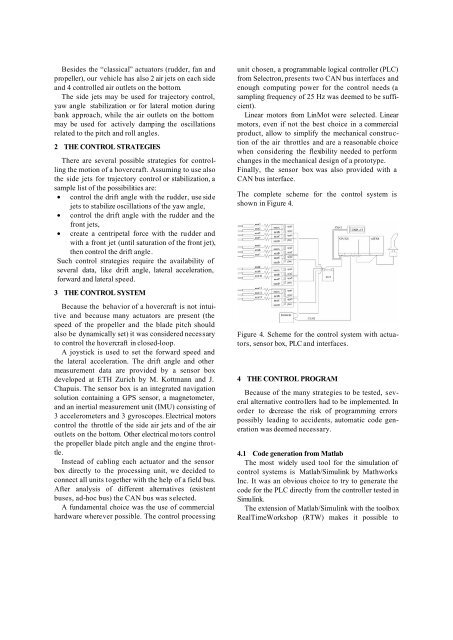
The complete scheme for the <strong>control</strong> system is<br />
shown in Figure 4.<br />
Figure 4. Scheme for the <strong>control</strong> system with actuators,<br />
sensor box, PLC and interfaces.<br />
4 THE CONTROL PROGRAM<br />
Because <strong>of</strong> the many strategies to be tested, several<br />
alternative <strong>control</strong>lers had to be implemented. In<br />
order to decrease the risk <strong>of</strong> programming errors<br />
possibly leading to accidents, automatic code generation<br />
was deemed necessary.<br />
4.1 Code generation from Matlab<br />
The most widely used tool for the simulation <strong>of</strong><br />
<strong>control</strong> systems is Matlab/Simulink by Mathworks<br />
Inc. It was an obvious choice to try to generate the<br />
code for the PLC directly from the <strong>control</strong>ler tested in<br />
Simulink.<br />
The extension <strong>of</strong> Matlab/Simulink with the toolbox<br />
RealTimeWorkshop (RTW) makes it possible to