Rapid control prototyping of a Hovercraft Silvano ... - ResearchGate
Rapid control prototyping of a Hovercraft Silvano ... - ResearchGate
Rapid control prototyping of a Hovercraft Silvano ... - ResearchGate

You also want an ePaper? Increase the reach of your titles
YUMPU automatically turns print PDFs into web optimized ePapers that Google loves.
<strong>Rapid</strong> <strong>control</strong> <strong>prototyping</strong> <strong>of</strong> a <strong>Hovercraft</strong><br />
<strong>Silvano</strong> Balemi*, Roberto Bucher*, Paola Guggiari*, Ivan Furlan*, Markus Kottmann°, Jacques Chapuis °<br />
*) Department <strong>of</strong> Computer Science and Electronics, University <strong>of</strong> Applied Sciences <strong>of</strong> Southern Switzerland,<br />
6928 Lugano-Manno, Switzerland ({silvano.balemi, roberto.bucher, paola.guggiari, ivan.furlan}@die.supsi.ch)<br />
°) Institut für Mess- und Regeltechnik, Swiss Federal Institute <strong>of</strong> Technology (ETH), 8092 Zurich, Switzerland<br />
(kottmann@imrt.mavt.ethz.ch, chapuis @imrt.mavt.ethz.ch)<br />
<strong>Rapid</strong> <strong>prototyping</strong> <strong>control</strong> systems play a central role in the development process <strong>of</strong> mechatronic systems.<br />
<strong>Rapid</strong> <strong>control</strong>ler <strong>prototyping</strong> can be reduced to the s<strong>of</strong>tware aspects by appropriate choice <strong>of</strong> <strong>control</strong> hardware.<br />
In this paper we show how a commercial PLC tied to Matlab/Simulink has been used to guide a hovercraft.<br />
1 INTRODUCTION<br />
In mechatronic systems , <strong>control</strong> issues play a central<br />
role. Verification <strong>of</strong> system choices must be performed<br />
as soon as possible in the development process.<br />
It is therefore <strong>of</strong>ten necessary to be able to<br />
check the desired performance at an early stage<br />
through the extensive use <strong>of</strong> rapid <strong>prototyping</strong> <strong>control</strong><br />
systems.<br />
In the reported project the <strong>control</strong> system <strong>of</strong> a<br />
high-performance hovercraft prototype built by Officina<br />
Borra SA had to be developed.<br />
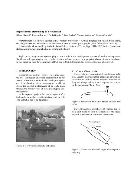
Figure 1. <strong>Hovercraft</strong> on the lake <strong>of</strong> Lugano<br />
1.1 Control <strong>of</strong> hove rcrafts<br />
<strong>Hovercraft</strong>s are underactuated amphibious vehicles.<br />
Usually, a horizontal fan creates an air cushion<br />
sustaining the vehicle, while a propeller produces the<br />
drag and a large rudder is used to guide the vehicle<br />
by the deviation <strong>of</strong> the air flow.<br />
Figure 2. <strong>Hovercraft</strong> with sustainment fan and propeller<br />
Curved trajectories are followed by letting the vehicle<br />
drift laterally: then the direction <strong>of</strong> the speed<br />
does not coincide with the axis <strong>of</strong> the vehicle.<br />
Trajectory tangent<br />
Data<br />
Velocity<br />
Figure 3. <strong>Hovercraft</strong> with drift angle with respect to<br />
trajectory
Besides the “classical” actuators (rudder, fan and<br />
propeller), our vehicle has also 2 air jets on each side<br />
and 4 <strong>control</strong>led air outlets on the bottom.<br />
The side jets may be used for trajectory <strong>control</strong>,<br />
yaw angle stabilization or for lateral motion during<br />
bank approach, while the air outlets on the bottom<br />
may be used for actively damping the oscillations<br />
related to the pitch and roll angles.<br />
2 THE CONTROL STRATEGIES<br />
There are several possible strategies for <strong>control</strong>ling<br />
the motion <strong>of</strong> a hovercraft. Assuming to use also<br />
the side jets for trajectory <strong>control</strong> or stabilization, a<br />
sample list <strong>of</strong> the possibilities are:<br />
• <strong>control</strong> the drift angle with the rudder, use side<br />
jets to stabilize oscillations <strong>of</strong> the yaw angle,<br />
• <strong>control</strong> the drift angle with the rudder and the<br />
front jets,<br />
• create a centripetal force with the rudder and<br />
with a front jet (until saturation <strong>of</strong> the front jet),<br />
then <strong>control</strong> the drift angle.<br />
Such <strong>control</strong> strategies require the availability <strong>of</strong><br />
several data, like drift angle, lateral acceleration,<br />
forward and lateral speed.<br />
3 THE CONTROL SYSTEM<br />
Because the behavior <strong>of</strong> a hovercraft is not intuitive<br />
and because many actuators are present (the<br />
speed <strong>of</strong> the propeller and the blade pitch should<br />
also be dynamically set) it was considered necessary<br />
to <strong>control</strong> the hovercraft in closed-loop.<br />
A joystick is used to set the forward speed and<br />
the lateral acceleration. The drift angle and other<br />
measurement data are provided by a sensor box<br />
developed at ETH Zurich by M. Kottmann and J.<br />
Chapuis. The sensor box is an integrated navigation<br />
solution containing a GPS sensor, a magnetometer,<br />
and an inertial measurement unit (IMU) consisting <strong>of</strong><br />
3 accelerometers and 3 gyroscopes. Electrical motors<br />
<strong>control</strong> the throttle <strong>of</strong> the side air jets and <strong>of</strong> the air<br />
outlets on the bottom. Other electrical mo tors <strong>control</strong><br />
the propeller blade pitch angle and the engine throttle.<br />
Instead <strong>of</strong> cabling each actuator and the sensor<br />
box directly to the processing unit, we decided to<br />
connect all units together with the help <strong>of</strong> a field bus.<br />
After analysis <strong>of</strong> different alternatives (existent<br />
buses, ad-hoc bus) the CAN bus was selected.<br />
A fundamental choice was the use <strong>of</strong> commercial<br />
hardware wherever possible. The <strong>control</strong> processing<br />
unit chosen, a programmable logical <strong>control</strong>ler (PLC)<br />
from Selectron, presents two CAN bus interfaces and<br />
enough computing power for the <strong>control</strong> needs (a<br />
sampling frequency <strong>of</strong> 25 Hz was deemed to be sufficient).<br />
Linear motors from LinMot were selected. Linear<br />
motors, even if not the best choice in a commercial<br />
product, allow to simplify the mechanical construction<br />
<strong>of</strong> the air throttles and are a reasonable choice<br />
when considering the flexibility needed to perform<br />
changes in the mechanical design <strong>of</strong> a prototype.<br />
Finally, the sensor box was also provided with a<br />
CAN bus interface.<br />
The complete scheme for the <strong>control</strong> system is<br />
shown in Figure 4.<br />
Figure 4. Scheme for the <strong>control</strong> system with actuators,<br />
sensor box, PLC and interfaces.<br />
4 THE CONTROL PROGRAM<br />
Because <strong>of</strong> the many strategies to be tested, several<br />
alternative <strong>control</strong>lers had to be implemented. In<br />
order to decrease the risk <strong>of</strong> programming errors<br />
possibly leading to accidents, automatic code generation<br />
was deemed necessary.<br />
4.1 Code generation from Matlab<br />
The most widely used tool for the simulation <strong>of</strong><br />
<strong>control</strong> systems is Matlab/Simulink by Mathworks<br />
Inc. It was an obvious choice to try to generate the<br />
code for the PLC directly from the <strong>control</strong>ler tested in<br />
Simulink.<br />
The extension <strong>of</strong> Matlab/Simulink with the toolbox<br />
RealTimeWorkshop (RTW) makes it possible to
automatically create generic C-code from a Simulink<br />
model. Within the reported project we adapted the<br />
generation <strong>of</strong> the C-code to match the needs <strong>of</strong> the<br />
PLC, making it possible to run a <strong>control</strong>ler previously<br />
tested with a simulation just in a few mouse clicks.<br />
download<br />
Figure 5. Automatic code generation for the PLC<br />
<strong>control</strong>ler from Matlab/Simulink<br />
4.2 The link between Simulink and the PLC<br />
Usually, the C-Code generation through the Matlab<br />
Toolbox “RealTimeWorkshop” requires two specific<br />
files:<br />
• The “Target Language Compiler” File<br />
• The “Template Makefile”<br />
The role <strong>of</strong> the “Target Language Compiler” file is<br />
to define the environment where the Code is integrated<br />
(program language, environment variables,<br />
<strong>control</strong> <strong>of</strong> the code generation). The “Template<br />
Makefile” describes all the information needed to<br />
compile the code (path, compilation flags) and is the<br />
basis for creating the “Project Makefile”.<br />
In our case, the integrated development environment<br />
(IDE) for the Selectron PLC dynamically generates<br />
an own Project Makefile each time the comp ilation<br />
is started; thus we can't exploit the external<br />
Makefile created by Matlab/Simulink. Moreover, it is<br />
not possible to add external files to the project, because<br />
the IDE is not able to recognize and to correctly<br />
link them. Even the command “gmake -f<br />
model.mk” does not work correctly.<br />
Thus, the standard procedures <strong>of</strong>fered by Real-<br />
TimeWorkshop were not completely applicable and<br />
we had to look for new ways to complete and integrate<br />
the generated code.<br />
In spite <strong>of</strong> all these limitations we succeeded, although<br />
with some loss <strong>of</strong> flexibility, in generating<br />
code for the PLC environment, and we completely<br />
automated the code generation from the Simulink<br />
model to the code downloaded into the Selectron<br />
PLC.<br />
4.2.1 Solutions to circumvent the IDE-specific<br />
limitations<br />
In order to solve these problems we had to:<br />
• use a preselected name for the code generated<br />
by RTW (modello.c), and to integrate it with the<br />
line "#include modello.c”,<br />
• include the code for the interface between the<br />
PLC and the Simulink in a file (main_166.c) and<br />
to integrate it with the line "#include<br />
main_166.c",<br />
• include all source files from RTW in the same<br />
way,<br />
• create the drivers to handle the I/O as so-called<br />
TLC files in order to avoid external sources<br />
(consequently it is impossible to write C-MEX<br />
S-Function to handle I/O functions),<br />
• integrate definition for the files from the "State<br />
Flow" toolbox using “#include" statements<br />
In order to correctly compile the Simulink files we<br />
further had to modify the file defining the "Makefile".<br />
This file, called "Ips.mk" contains all flags and the<br />
path needed to compile and link the project. In particular<br />
we had to add some new definitions for the<br />
Matlab and the RTW environment. The file is given<br />
below:<br />
MAT_DIR=c:\matlabr12<br />
MAT_INC=-I$(MAT_DIR)\simulink\include -<br />
I$(MAT_DIR)\extern\include<br />
RTW_INC=-I$(MAT_DIR)\rtw\c\src -<br />
I$(MAT_DIR)\rtw\c\libsrc<br />
MATLAB_D=-DMODEL=MODELLO -DRT -DDSP32 -<br />
DNUMST=1 -DNCSTATES=0 -DTID01EQ=0<br />
...<br />
ifreq '$(BOARD_TYP)' 'CPU721'<br />
BINC =$(BASE)/inc $(MATLAB_I)<br />
...<br />
CDEFS=-D__HWTYP_CPC721__ $(MATLAB_D)
4.2.2 The steps for the code generation<br />
It was now possible to simply generate the PLC<br />
code according to the following steps:<br />
• Design the <strong>control</strong> system with Simulink and<br />
Stateflow,<br />
• Generate the C-Code using RTW (mo dello.c<br />
modello.h, modello.reg and mo dello.prm), see<br />
figure 6,<br />
• Compile the code in the Selectron IDE, see figure<br />
7,<br />
• Download the code to the PLC from the Selectron<br />
IDE.<br />
Figure 6. Automatic code generation for the PLC<br />
<strong>control</strong>ler from Matlab/Simulink<br />
Figure 7. Selectron compilation process<br />
4.2.3 I/O blocks<br />
All PLC I/O blocks are implemented in Simulink as<br />
C-MEX S-Function and TLC modules (see Figure 8).<br />
The C-MEX S-Function is only responsible for defining<br />
the different inputs and outputs. The C-Code<br />
to implement the function <strong>of</strong> a single module is defined<br />
in corresponding “TLC” files.<br />
Figure 8. Simulink library for I/O blocks<br />
4.3 Integration with additional code<br />
The PCL C-code is divided into two parts:<br />
1. The external code generated by Simulink<br />
2. The C-code written directly in the Selectron IDE<br />
The code generated by Simulink is responsible for:<br />
• computing the motor positions from the sensor<br />
data and pilot inputs according to the desired<br />
<strong>control</strong> policies,<br />
• monitoring the status <strong>of</strong> the motor drives and <strong>of</strong><br />
the sensor box.<br />
The C-code generated in the Selectron IDE handles<br />
the<br />
• PLC display,<br />
• the link between analog and digital PLC inputs<br />
and outputs,<br />
• the communication over the CAN Bus.<br />
In order to exchange data between the Simulink and<br />
the PLC code global variables are used.
5 CONCLUSIONS<br />
The reported work shows how rapid <strong>control</strong> <strong>prototyping</strong><br />
can be used to speed up the development<br />
process <strong>of</strong> <strong>control</strong> systems and to increase reliability<br />
during the testing phase. Current s<strong>of</strong>tware tools<br />
allow the use <strong>of</strong> these techniques on the definitive<br />
hardware, simplifying the transition from the prototype<br />
to the future product.<br />
The implemented system has been applied to and<br />
tested on a hovercraft. Extensive testing <strong>of</strong> the <strong>control</strong>led<br />
behavior <strong>of</strong> the vehicle was not possible because<br />
a new mechanical design was soon recognized<br />
to be necessary. However, the presented <strong>control</strong><br />
system will certainly speed up the testing phase <strong>of</strong><br />
the hovercraft and build the core for the <strong>control</strong><br />
hardware present in the future product.<br />
REFERENCES<br />
1. R. Hayashi, K. Osuka, T. Ono, Trajectory <strong>control</strong><br />
<strong>of</strong> an air cushion vehicle, Proceedings <strong>of</strong> the<br />
IEEE/RJS/GI International Conference on Intelligent<br />
Systems, Vol.3, 1994<br />
2. C. Eck, J. Chapuis, H. P. Geering, "S<strong>of</strong>tware-<br />
Supported Design and Evaluation <strong>of</strong> low-cost<br />
Navigation Units," Proceedings <strong>of</strong> the 8th Saint<br />
Peterburg International Conference on Integrated<br />
Navigations Systems, pp. 163-172, St. Petersburg,<br />
Russia, May 2001.<br />
3. C. Eck, H. P. Geering, S. C. Bose, "Model Based<br />
INS/GPS Navigation," Proceedings <strong>of</strong> the 7th<br />
Saint Peterburg International Conference on Integrated<br />
Navigations Systems, pp. 95-102,St. Petersburg,<br />
Russia, May 2000.