HHPC-2 Handheld Airborne Particle Counter Operator Manual
HHPC-2 Handheld Airborne Particle Counter Operator Manual
HHPC-2 Handheld Airborne Particle Counter Operator Manual
Create successful ePaper yourself
Turn your PDF publications into a flip-book with our unique Google optimized e-Paper software.
KSS - March 2005 - Edition 2<br />
<strong>HHPC</strong>-2 <strong>Handheld</strong> <strong>Particle</strong> <strong>Counter</strong> - Annex 43 of 46<br />
Annex<br />
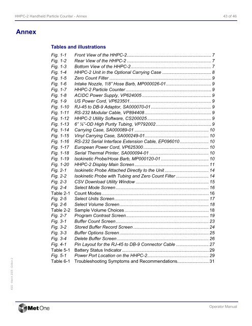
Tables and illustrations<br />
Fig. 1-1 Front View of the <strong>HHPC</strong>-2................................................................... 7<br />
Fig. 1-2 Rear View of the <strong>HHPC</strong>-2 ................................................................... 7<br />
Fig. 1-3 Bottom View of the <strong>HHPC</strong>-2................................................................ 7<br />
Fig. 1-4 <strong>HHPC</strong>-2 Unit in the Optional Carrying Case ....................................... 8<br />
Fig. 1-5 Zero Count Filter ................................................................................. 9<br />
Fig. 1-6 Intake Nozzle, 1/8” Hose Barb, MP000026-01.................................... 9<br />
Fig. 1-7 <strong>HHPC</strong>-2 <strong>Particle</strong> <strong>Counter</strong> .................................................................... 9<br />
Fig. 1-8 AC/DC Power Supply, VP624005 ....................................................... 9<br />
Fig. 1-9 US Power Cord, VP623501................................................................. 9<br />
Fig. 1-10 RJ-45 to DB-9 Adaptor, SA000070-01................................................ 9<br />
Fig. 1-11 RS-232 Modular Cable, VP894408 ..................................................... 9<br />
Fig. 1-12 <strong>HHPC</strong>-2 Utility Software, CS200025 ................................................... 9<br />
Fig. 1-13 6” ¼”-OD High Purity Tubing, VP792002 ............................................ 9<br />
Fig. 1-14 Carrying Case, SA000089-01 ........................................................... 10<br />
Fig. 1-15 Vinyl Carrying Case, SA000249-01................................................... 10<br />
Fig. 1-16 RS-232 Serial Interface Extension Cable, EP096010 ....................... 10<br />
Fig. 1-17 European Power Cord, VP625300.................................................... 10<br />
Fig. 1-18 Serial Thermal Printer, SA000094-01 ............................................... 10<br />
Fig. 1-19 Isokinetic Probe/Hose Barb, MP000120-01 ...................................... 10<br />
Fig. 1-20 <strong>HHPC</strong>-2 Display Main Screen ........................................................... 11<br />
Fig. 2-1 Isokinetic Probe Attached Directly to the Unit ................................... 14<br />
Fig. 2-2 Isokinetic Probe with Tubing and Zero Count Filter .......................... 14<br />
Fig. 2-3 CSV Download Utility Window .......................................................... 15<br />
Fig. 2-4 Select Mode Screen.......................................................................... 16<br />
Table 2-1 Count Modes..................................................................................... 16<br />
Fig. 2-5 Select Units Screen........................................................................... 17<br />
Fig. 2-6 Select Volume Screen....................................................................... 18<br />
Table 2-2 Sample Volume Choices................................................................... 18<br />
Fig. 2-7 Program Contrast Screen.................................................................. 19<br />
Fig. 3-1 Buffer Count Screen.......................................................................... 23<br />
Fig. 3-2 Stored Buffer Record Screen ............................................................ 24<br />
Fig. 3-3 Buffer Options Screen....................................................................... 25<br />
Fig. 3-4 Delete Buffer Screen......................................................................... 26<br />
Fig. 4-1 Pin Layout for the RJ-45 to DB-9 Connector Cable .......................... 27<br />
Table 5-1 Battery Status Indicator ..................................................................... 29<br />
Fig. 5-1 Power Port Location on the <strong>HHPC</strong>-2................................................. 29<br />
Table 6-1 Troubleshooting Symptoms and Recommendations......................... 31<br />
<strong>Operator</strong> <strong>Manual</strong>


