STIGA PARK
STIGA PARK
STIGA PARK

Create successful ePaper yourself
Turn your PDF publications into a flip-book with our unique Google optimized e-Paper software.
BRUKSANVISNING SV ....8<br />
KÄYTTÖOHJEET FI ...19<br />
BRUGSANVISNING DA..30<br />
BRUKSANVISNING NO .41<br />
GEBRAUCHSANWEISUNG DE...52<br />
INSTRUCTIONS FOR USE EN...64<br />
MODE D’EMPLOI FR....75<br />
GEBRUIKSAANWIJZING NL...86<br />
8211-0540-02<br />
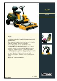
<strong>STIGA</strong> <strong>PARK</strong><br />
4WD<br />
PRO 25<br />
PRO 20<br />
PRO 16<br />
PRO Svan
2<br />
1<br />
3<br />
5<br />
A<br />
B<br />
C<br />
G<br />
N<br />
O<br />
S T<br />
D<br />
E<br />
Pro20 Pro25<br />
Pro Svan<br />
H I J K L<br />
M<br />
F<br />
2<br />
4<br />
6<br />
P<br />
Q<br />
R<br />
G<br />
N<br />
Pro16<br />
H I J K
7<br />
9<br />
U<br />
V<br />
11<br />
W<br />
W<br />
Pro16 Pro20<br />
Pro Svan<br />
8<br />
Max<br />
10<br />
12<br />
Pro25<br />
Pro25<br />
W<br />
X<br />
3
4<br />
13<br />
15<br />
17<br />
Z<br />
Y<br />
10 Ampere<br />
Pro16 Pro20<br />
Pro Svan<br />
Y<br />
14<br />
16<br />
B<br />
A<br />
0<br />
1<br />
18<br />
Pro25<br />
Pro16 Pro20<br />
Z<br />
Y
19<br />
21<br />
23<br />
Z<br />
Pro25<br />
20<br />
22<br />
24<br />
F<br />
G<br />
H<br />
5
25<br />
27<br />
29<br />
6<br />
B E<br />
A<br />
Pro25<br />
E<br />
C<br />
D<br />
26<br />
28<br />
30<br />
Pro16 Pro20<br />
A<br />
Pro Svan<br />
B
31<br />
33<br />
32<br />
7
64<br />
EN<br />
1 GENERAL<br />
This symbol indicates WARNING. Serious<br />
personal injury and/or damage to<br />
property may result if the instructions<br />
are not followed carefully.<br />
You must read these instructions for use<br />
and the accompanying pamphlet<br />
“SAFETY INSTRUCTIONS” carefully,<br />
before starting up the machine.<br />
1.1 SYMBOLS<br />
The following symbols appear on the machine.<br />
They are there to remind you of the care and attention<br />
required during use and maintenance.<br />
This is what the symbols mean:<br />
Warning!<br />
Read the instruction manual and the safety<br />
manual before using the machine.<br />
Warning!<br />
Watch out for discarded objects. Keep onlookers<br />
away.<br />
Warning!<br />
Always wear hearing protectors.<br />
Warning!<br />
This machine is not designed to be driven<br />
on public roads.<br />
Warning!<br />
The machine, equipped with original accessories,<br />
must not be driven in any direction<br />
on slopes with a gradient greater than<br />
10º.<br />
Warning!<br />
Risk of crushing injuries. Keep hands and<br />
feet well away from the articulated steering<br />
joint.<br />
Warning!<br />
Risk of burn injuries. Do not touch the silencer/catalytic<br />
converter.<br />
1.2 References<br />
1.2.1 Figures<br />
The figures in these instructions for use are numbered<br />
1, 2, 3, etc.<br />
Components shown in the figures are marked A, B,<br />
C, etc.<br />
A reference to component C in figure 2 is written<br />
“2:C”.<br />
1.2.2 Headings<br />
The headings in these instructions for use are numbered<br />
in accordance with the following example:<br />
“1.3.1 General safety check” is a subheading to<br />
“1.3 Safety checks” and is included under this<br />
heading.<br />
When referring to headings, only the number of the<br />
heading is normally specified. E.g. “See 1.3.1”.<br />
ENGLISH<br />
2 DESCRIPTION<br />
2.1 Drive<br />
The machine has 4-wheel drive. The power from<br />
the engine to the drive wheels is transferred hydraulically.<br />
The engine drives an oil pump, which<br />
pumps oil through the rear and front axle drives.<br />
The front axle and rear axle are connected in series,<br />
which means that the front wheels and rear<br />
wheels are forced to rotate at the same speed.<br />
To make turning easier, both axles are equipped<br />
with differential.<br />
Front-mounted implements are powered via drive<br />
belts.<br />
2.2 Steering<br />
The machine is articulated. This means that the<br />
chassis is divided into a front and a rear section,<br />
which can be turned in relation to each other.<br />
The articulated steering means that the machine<br />
can turn around trees and other obstacles with an<br />
extremely small turning radius.<br />
2.3 Safety system<br />
The machine is equipped with an electrical safety<br />
system. The safety system interrupts certain activities<br />
that can entail a danger of incorrect manoeuvres.<br />
For example, the engine cannot be started if<br />
the clutch-parking brake pedal is depressed.<br />
The operation of the safety system must<br />
always be checked every time before<br />
use.<br />
2.4 Controls<br />
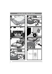
2.4.1 Implement lifter, mechanical (3:C)<br />
(Pro16)<br />
To switch between working position and transport<br />
position:<br />
1. Depress the pedal fully.<br />
2. Release the pedal slowly.<br />
2.4.2 Implement lifter, hydraulic (5:M)<br />
(Pro20, Pro25, Pro Svan)<br />
The hydraulic implement lifter only<br />
works when the engine is running, and is<br />
controlled with the switch (5:M).<br />
The switch has the following three positions:<br />
• Floating position. Press the front part of the<br />
switch. The switch locks in the pressed position<br />
and the implement is lowered until it reaches its<br />
floating position.<br />
Floating position means that the implement always<br />
rests with the same pressure against the<br />
ground and can follow the ground’s contours.<br />
Floating position should be used when working.
• Lifting. Press the rear part of the switch until<br />
the implement is in its highest position (transport<br />
position). Then release the switch and the<br />
height is locked in transport position.<br />
• Locking in transport position. The switch has<br />
reverted to neutral position after lifting. The implement<br />
is locked in transport position.<br />
NOTE! The hydraulic implement lifter must be<br />
in floating position in order for the power takeoff<br />
to be engaged.<br />
NOTE! The power take-off cannot be engaged<br />
when the parking brake is activated.<br />
2.4.3 Clutch-parking brake (3:B)<br />
Never press the pedal while driving.<br />
There is a risk of overheating in the<br />
power transmission.<br />
The pedal (3:B) has the following<br />
three positions:<br />
• Released. The clutch is not activated. The parking<br />
brake is not activated.<br />
• Depressed halfway. Forward drive disengaged.<br />
The parking brake is not activated.<br />
• Pressed down. Forward drive disengaged. The<br />
parking brake is fully activated but not locked.<br />
•<br />
2.4.4 Inhibitor, parking brake (3:A)<br />
The inhibitor locks the “clutch-brake”<br />
pedal in the depressed position. This function<br />
is used to lock the machine on slopes,<br />
during transport, etc., when the engine is<br />
not running.<br />
The parking brake must always be released<br />
during operation.<br />
Locking:<br />
1. Depress the pedal (3:B) fully.<br />
2. Move the inhibitor (3:A) to the right.<br />
3. Release the pedal (3:B).<br />
4. Release the inhibitor (3:A).<br />
Unlocking:<br />
Press and release the pedal (3:B).<br />
ENGLISH EN<br />
2.4.5 Driving-service brake (3:F)<br />
The pedal (3:F) determines the gearing ratio between<br />
the engine and the drive wheels (= the<br />
speed). When the pedal is released, the service<br />
brake is activated.<br />
1. Press the pedal forward –<br />
the machine moves forward.<br />
2. No load on the pedal – the machine<br />
is stationary.<br />
3. Press the pedal backward –<br />
the machine reverses.<br />
4. Reduce the pressure on the<br />
pedal – the machine brakes.<br />
2.4.6 Steering wheel (3:D)<br />
The height of the steering wheel is infinitely adjustable.<br />
Undo the adjustment knob (3:E) on the<br />
steering column and raise or lower the steering<br />
wheel to the desired position. Tighten.<br />
Do not adjust the steering wheel during<br />
operation.<br />
Never turn the steering wheel when the<br />
machine is stationary with a lowered<br />
implement. There is a risk of abnormal<br />
loads on the servo and steering mechanisms.<br />
2.4.7 Throttle control (4,5:G)<br />
Control for setting the engine’s revs.<br />
1. Full throttle – when the machine is in<br />
operation, full throttle should always be<br />
used.<br />
2. Idling.<br />
2.4.8 Choke control (4,5:H)<br />
A pull-type control to choke the engine when starting<br />
from cold.<br />
1. Control fully pulled out – choke valve<br />
in carburettor closed. For starting cold engine.<br />
2. Control pushed in – choke valve open.<br />
For starting warm engine and when operating<br />
the machine.<br />
Never operate the machine with the choke<br />
pulled out when the engine is warm.<br />
2.4.9 Ignition lock/headlight (4,5:I)<br />
The ignition lock is used for starting and stopping<br />
the engine. The ignition lock is also the switch for<br />
the headlight.<br />
65
66<br />
EN<br />
Do not leave the machine with the key<br />
in position 2 or 3. There is a fire risk,<br />
fuel can run into the engine through the<br />
carburettor, and there is a risk of the<br />
battery being discharged and damaged.<br />
Four positions:<br />
1. Stop position – the engine is short-circuited.<br />
The key can be removed.<br />
2. Operating position – headlight activated.<br />
3. Operating position – headlight not activated.<br />
4. Start position – the electric start motor<br />
is activated when the key is turned to the<br />
spring-loaded start position. Once the engine<br />
has started, let the key return to operating<br />
position 3.<br />
Turn the key to position 2 to light the<br />
headlight.<br />
2.4.10 Power take-off (4,5:K)<br />
Switch for engaging/disengaging the electromagnetic<br />
power take-off for operating front-mounted<br />
accessories. Two positions:<br />
1. Press the front part of the switch – the<br />
power take-off is engaged. The symbol<br />
will light up.<br />
2. Press the rear part of the switch – the<br />
power take-off is disengaged.<br />
2.4.11 Hour meter (2:P)<br />
Indicates the number of working hours. Only<br />
works when the engine is running.<br />
2.4.12 Cruise control (5, 6:N)<br />
A switch for activating the cruise control. The<br />
cruise control locks the pedal (3:F) in the desired<br />
position.<br />
1. Press down the pedal (3:F) until the desired<br />
speed is obtained. Then press the<br />
front part of the switch to activate the<br />
cruise control. The symbol will light up.<br />
2. Disengage the cruise control by releasing<br />
it with the pedal (3:B) or pressing the<br />
rear part of the switch.<br />
2.4.13 Cutting height adjustment (4,5:J)<br />
The machine is equipped with a control for using<br />
the cutting deck with electrical cutting height adjustment.<br />
The switch is used to adjust the cutting<br />
height in continuously variable positions.<br />
The cutting deck is connected to the contact (2:Q).<br />
ENGLISH<br />
2.4.14Rear Rake (5:L)<br />
(Pro20, Pro25, Pro Svan)<br />
The machine is fitted with a control for electrical<br />
adjustment of a rear rake (available as an<br />
accessory).<br />
The switch is used to raise and lower the<br />
rear rake.<br />
Cables for connecting the rear rake are found at the<br />
rear of the machine, to the left of the upper side of<br />
the bumper. (Pro16 is prepared for a rear rake,<br />
cables routed).<br />
2.4.15 Sand spreader (6:O)<br />
(Pro20, Pro25, Pro Svan)<br />
The machine has been designed for electrical adjustment<br />
of a sand spreader (accessory).<br />
12V<br />
The switch is used to start and stop the<br />
spreader.<br />
Cables for connecting the sand spreader are at the<br />
rear of the machine. (Pro16 is prepared for a sand<br />
spreader, cables routed).<br />
2.4.16 Clutch release lever (6:R)<br />
A lever for disengaging the variable transmission.<br />
Enables the machine to be moved by hand without<br />
the help of the engine. Two positions:<br />
1. Lever out – transmission engaged<br />
for normal operation.<br />
There is an audible click when<br />
the lever locks in the outer position.<br />
2. Lever in – transmission disengaged.<br />
The machine can be<br />
moved by hand.<br />
The machine may not be towed over long distances<br />
or at high speeds. The transmission could be damaged.<br />
2.4.17 Seat (1:T)<br />
The seat can be folded and adjusted frontrear.<br />
The seat can be adjusted as follows:<br />
1. Move the control lever (1:T) upwards.<br />
2. Set the seat to the desired position.<br />
3. Release the control lever (1:S) to lock<br />
the seat.<br />
The seat is equipped with a safety switch that is<br />
connected to the machine’s safety system. This<br />
means that certain dangerous activities are not possible<br />
when there is nobody sitting on the seat. Also<br />
see 4.3.2.<br />
2.4.18 Engine casing (7:U)<br />
In order to access the fuel cock, battery<br />
and engine, the machine has an engine<br />
casing that can be opened. The engine casing<br />
is locked with a rubber strap.
The engine casing is opened as follows:<br />
1. Undo the rubber strap (7:V) at the front edge of<br />
the casing.<br />
2. Carefully lift the engine casing back.<br />
Close in the reverse order.<br />
The machine may not be operated unless<br />
the engine casing is closed and<br />
locked. Risk of burns and crushing injuries.<br />
3 AREAS OF USE<br />
The machine may only be used for the following<br />
tasks using the genuine <strong>STIGA</strong> accessories stated.<br />
Work Accessories, <strong>STIGA</strong> genuine<br />
Mowing Using mowing decks:<br />
107 M, 107 M HD, 107 M HD<br />
El, 121 M, 121 M El, 125 Combi<br />
Pro, 125 Combi Pro El and with<br />
flail mower.<br />
Sweeping Using brush unit or collector<br />
brush unit. The use of a dust<br />
guard is recommended with the<br />
first option.<br />
Snow clearance Using snow blade or snow<br />
thrower Snow chains are recommended.<br />
Grass clipping and Using towed collector 30" or<br />
leaf collection 42".<br />
Grass and leaf Using dump cart Standard, Maxi<br />
transport or Combi.<br />
Sand spreading Using sand spreader. Can also<br />
be used for spreading salt. Snow<br />
chains are recommended.<br />
Weeding on gravel Using front-mounted hoe.<br />
paths<br />
Lawn edge trim- Using edge trimmer.<br />
ming<br />
Moss scarification Using moss scarifier.<br />
The maximum vertical load on the towing hitch<br />
must not exceed 100 N.<br />
The maximum over-run load on the towing hitch<br />
from towed accessories must not exceed 500 N.<br />
NOTE! Before using a trailer – contact your insurance<br />
company.<br />
NOTE! This machine is not intended to be driven<br />
on public roads.<br />
ENGLISH EN<br />
4 STARTING AND OPERATION<br />
The machine may not be operated unless<br />
the engine casing is closed and<br />
locked. Risk of burns and crushing injuries.<br />
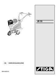
4.1 Filling with petrol<br />
Always use lead-free petrol. You must never use 2stroke<br />
petrol mixed with oil.<br />
The tank holds 14 litres. The level can easily be<br />
read through the transparent tank.<br />
NOTE! Ordinary lead-free petrol is a perishable<br />
and must not be stored for more than 30 days.<br />
Environmental petrol can be used, i.e. alkylate<br />
petrol. This type of petrol has a composition that is<br />
less harmful for people and nature.<br />
Petrol is highly inflammable. Always<br />
store fuel in containers that are made<br />
especially for this purpose.<br />
Only fill or top up with petrol outdoors,<br />
and never smoke when filling or topping<br />
up. Fill up with fuel before starting<br />
the engine. Never remove the filler cap<br />
or fill with petrol while the engine is<br />
running or still warm.<br />
Never completely fill the petrol tank. Leave an<br />
empty space (= at least the entire filler tube plus 1<br />
- 2 cm at the top of the tank) to allow the petrol to<br />
expand when it warms up without overflowing.<br />
See fig. 8.<br />
4.2 Checking the engine oil level<br />
On delivery, the Pro 16 and Pro 20 (Briggs & Stratton)<br />
are filled with SAE 30 oil.<br />
On delivery, the Pro 25 (Kohler) and Pro Svan<br />
(Honda) are filled with SAE 10W-40 oil.<br />
Check the oil level every time before using to<br />
ensure it is correct. The machine should be<br />
standing on level ground.<br />
Wipe around the dipstick. Unscrew and<br />
pull it up. Wipe the dipstick.<br />
Pro 16, Pro 20, Pro25:<br />
Push the dipstick down completely and screw into<br />
place.<br />
Unscrew and pull the dipstick up again. Read off<br />
the oil level.<br />
Pro Svan:<br />
Push the dipstick down completely without screwing<br />
it into place. Pull it up again and read off the oil<br />
level.<br />
Top up with oil to the “FULL” mark if the oil level<br />
is below this mark. See fig. 9-11.<br />
67
68<br />
EN<br />
The oil level must never exceed the “FULL” mark.<br />
This results in the engine overheating. If the oil<br />
level exceeds the “FULL” mark, the oil must be<br />
drained until the correct level is achieved.<br />
4.3 Safety checks<br />
Check that the results of the safety checks below<br />
are achieved when testing the machine in question.<br />
The safety checks must always be carried<br />
out every time before use.<br />
If any of the results below is not<br />
achieved, the machine must not be<br />
used! Take the machine to a service<br />
workshop for repair.<br />
4.3.1 General safety check<br />
Object Result<br />
Fuel lines and con- No leaks.<br />
nections.<br />
Electrical cables. All insulation intact.<br />
No mechanical damage.<br />
Exhaust system. No leaks at connections.<br />
All screws tightened.<br />
Oil lines No leaks. No damage.<br />
Drive the machine The machine will stop.<br />
forwards/backwards<br />
and release<br />
the driving-service<br />
brake pedal.<br />
Test driving No abnormal vibrations.<br />
No abnormal sound.<br />
4.3.2 Electrical safety check<br />
The operation of the safety system<br />
should always be checked every time<br />
before use.<br />
Status Action Result<br />
The clutch-brake<br />
pedal is not<br />
depressed.<br />
The power take-off<br />
is not activated.<br />
The clutch-brake<br />
pedal is depressed.<br />
The power take-off<br />
is activated.<br />
Engine running.<br />
The power take-off<br />
is activated.<br />
Try to start. The engine<br />
will not start.<br />
The driver gets up<br />
from the seat.<br />
The driver gets up<br />
from the seat.<br />
Engine running. Remove fuse 10<br />
A.<br />
See fig. 13.<br />
The engine<br />
will not start.<br />
The power<br />
take-off will<br />
be disen-<br />
gaged.<br />
The engine<br />
will stop.<br />
ENGLISH<br />
Status Action Result<br />
Cruise control activated.<br />
The driver gets up<br />
from the seat.<br />
The cruise<br />
control will<br />
be disen-<br />
gaged.<br />
Cruise control acti- The clutch-brake The cruise<br />
vated.<br />
pedal is depressed. control will<br />
be disengaged.<br />
The switch for the Try to engage the It will not be<br />
implement lifter is power take-off. possible to<br />
in neutral position.<br />
engage the<br />
(not Pro16)<br />
power takeoff.<br />
4.4 Start<br />
1. Open the fuel cock. See 14.<br />
2. Check that the spark plug cable(s) is/are installed<br />
on the spark plug(s).<br />
3. Check to make sure that the power take-off is<br />
disengaged.<br />
4. Do not keep your foot on the drive pedal (3:F).<br />
5. Put the throttle control at full throttle.<br />
Starting cold engine – pull the choke control out<br />
fully.<br />
Starting warm engine – the choke control<br />
should be pressed in.<br />
6. Depress the clutch-brake pedal (3:B) fully.<br />
7. Turn the ignition key and start the engine.<br />
8 Once the engine has started, push the choke<br />
control in gradually if it has been used.<br />
9. When starting from cold, do not make the machine<br />
work under load immediately, but let the<br />
engine run for a few minutes first. This will allow<br />
the oil to warm up.<br />
When the machine is in operation, full throttle<br />
should always be used.<br />
4.5 Power assisted steering<br />
(Pro20, Pro25, Pro Svan)<br />
Power assisted steering means that power from the<br />
machine’s hydraulic system is supplied to the<br />
steering wheel movements. This makes the machine<br />
very easy to steer when the engine is operating<br />
at working revs (full throttle).<br />
The servo effect is reduced as the engine speed<br />
drops.<br />
4.6 Operating tips<br />
Always check that there is the correct volume of<br />
oil in the engine. This is particularly important<br />
when operating on slopes. See 4.2.
Be careful when driving on slopes. No<br />
sudden starting or stopping when driving<br />
up or down a slope. Never drive<br />
across a slope. Move from the top down<br />
or from the bottom to the top.<br />
The machine may not be driven on<br />
slopes greater than 10º in any direction.<br />
Reduce the speed on slopes and when<br />
making sharp turns in order to retain<br />
control and reduce the risk of tipping<br />
over.<br />
Do not turn the steering wheel to full<br />
lock when driving in top gear and at full<br />
throttle. The machine can easily topple<br />
over.<br />
Keep hands and fingers well away from<br />
articulated steering joint and seat<br />
bracket. Risk of crushing injuries. Never<br />
drive with the engine casing open.<br />
4.7 Stop<br />
Disengage the power take-off. Apply the parking<br />
brake.<br />
Allow the engine to idle 1-2 mins. Stop the engine<br />
by turning off the ignition key.<br />
Shut off the petrol cock. This is particularly important<br />
if the machine is to be transported on a trailer<br />
for example.<br />
If the machine is left unattended, remove<br />
the spark plug cable(s) and remove<br />
the ignition key.<br />
The engine may be very warm immediately<br />
after it is shut off. Do not touch the<br />
silencer, cylinder or cooling fins. This<br />
can cause burn injuries.<br />
4.8 Cleaning<br />
To reduce the risk of fire, keep the engine,<br />
silencer, battery and fuel tank free<br />
from grass, leaves and oil.<br />
To reduce the risk of fire, regularly<br />
check the machine for oil and/or fuel<br />
leakage.<br />
Clean the machine after each use. The following<br />
instructions apply for cleaning:<br />
• When washing the machine with water under<br />
high pressure, do not point the jet directly at<br />
axle seals, electrical components or hydraulic<br />
valves.<br />
• Do not spray water directly at the engine.<br />
• Clean the engine with a brush and/or compressed<br />
air.<br />
• Clean the engine’s cooling air intake (9-11:W).<br />
• Only Pro25: Clean the oil cooler (12:X).<br />
ENGLISH EN<br />
5 MAINTENANCE<br />
5.1 Service programme<br />
In order to keep the machine in good condition as<br />
regards reliability and operational safety as well as<br />
from an environmental perspective, <strong>STIGA</strong>’s Service<br />
programme should be followed.<br />
The contents of this programme can be found in<br />
the attached service log.<br />
Basic service must always be carried out by an authorised<br />
workshop.<br />
First service and intermediate service should be<br />
carried out by an authorised workshop, but can<br />
also be carried out by the user. The content of this<br />
can be found in the service log and the actions are<br />
described under “4 STARTING AND OPERA-<br />
TION” as well as below.<br />
Servicing carried out at an authorised workshop<br />
guarantees professional work using genuine spare<br />
parts.<br />
At each basic service and intermediate service carried<br />
out at an authorised workshop, the service log<br />
is stamped. A service log presenting these services<br />
is a valuable document that improves the machine’s<br />
second-hand value.<br />
5.2 Preparation<br />
All service and all maintenance must be carried out<br />
on a stationary machine with the engine switched<br />
off.<br />
Prevent the machine from rolling by always<br />
applying the parking brake.<br />
Stop the engine.<br />
Prevent unintentional starting of the<br />
engine by disconnecting the spark plug<br />
cable(s) from the spark plug(s) and removing<br />
the ignition key.<br />
5.3 Tyre pressure<br />
Adjust the air pressure in the tyres as follows:<br />
Front: 0.6 bar (9 psi).<br />
Rear: 0.4 bar (6 psi).<br />
5.4 Changing engine oil, filter<br />
This section contains tables covering the different<br />
engines that are included in <strong>STIGA</strong>’s Pro range. To<br />
facilitate reading, mark the data that applies to the<br />
relevant machine/engine.<br />
69
70<br />
EN<br />
5.4.1 Change intervals<br />
The table below states hours of operation and calendar<br />
months. Carry out the relevant action at<br />
whichever occurs first.<br />
Machine<br />
1st time Then at<br />
intervals of<br />
Pro16 Pro20 (B&S) Hours of operation/Calendar<br />
months<br />
Changing the oil<br />
5 hours<br />
50 hours/<br />
12 months<br />
Replacing the filter. - 100 hours<br />
Pro25 (Kohler) Hours of operation/Calendar<br />
months<br />
Changing the oil - 100 hours<br />
Replacing the filter. - 200 hours<br />
Pro Svan (Honda) Hours of operation/Calendar<br />
months<br />
Changing the oil 20 hours/ 100 hours/<br />
1 month 6 months<br />
Replacing the filter.<br />
-<br />
100 hours/<br />
6 months<br />
Change the oil more frequently if the engine has to<br />
operate in demanding conditions or if the ambient<br />
temperature is high.<br />
5.4.2 Engine Oil<br />
Use synthetic oil according to the table below.<br />
Machine Oil<br />
Pro16 Pro20 (B&S) Grade Service<br />
class<br />
All temperatures SAE 10W-30 SF<br />
Below -18° C SAE 5W-30 or higher<br />
Above 0° C SAE30<br />
Pro25 (Kohler) Grade Service<br />
class<br />
Above -18° C SAE 10W-30 SG<br />
Below 0° C SAE 5W-20/30 or higher<br />
Pro Svan (Honda) Grade Service<br />
class<br />
All temperatures SAE 10W-30 SJ<br />
Below 0° C SAE 5W-30 or higher<br />
Above 10° C SAE30<br />
Use oil without any additives.<br />
Do not fill with too much oil. This can cause the<br />
engine to overheat.<br />
Change oil when the engine is warm.<br />
ENGLISH<br />
The engine oil may be very hot if it is<br />
drained off directly after the engine is<br />
shut off. Therefore allow the engine to<br />
cool a few minutes before draining the<br />
oil.<br />
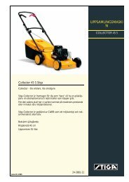
1. Attach the clamp on the oil drainage hose. Use<br />
a polygrip or similar. See fig. 15-17:Y.<br />
2. Move the clamp up 3-4 cm on the oil drainage<br />
hose and pull out the plug.<br />
3. Collect the oil in a collection vessel.<br />
NOTE! Do not spill any oil on the drive belts.<br />
4. Hand in the oil for disposal in accordance with<br />
local provisions.<br />
5. Install the oil drainage plug and move the clamp<br />
back so that it clamps above the plug.<br />
6. If the oil filter is to be replaced, see 5.4.3 below<br />
before continuing.<br />
7. Remove the dipstick and fill with new oil.<br />
Oil quantity:<br />
Machine Oil quantity, approximately<br />
No filter Filter replace-<br />
replacement ment<br />
Pro16, Pro20 1.6 litres 1.7 litres<br />
Pro25 2.0 litres 2.1 litres<br />
Pro Svan 0.9 litres 1.05 litres<br />
8. After filling up the oil, start the engine and idle<br />
for 30 seconds.<br />
9. Check to see if there is any oil leakage.<br />
10.Stop the engine. Wait for 30 seconds and then<br />
check the oil level in accordance with 4.2.<br />
5.4.3 Oil filter<br />
First drain the engine oil and install the oil drainage<br />
plug as described above. Then replace the oil<br />
filter as follows:<br />
Pro 16, Pro 20, Pro Svan:<br />
1. Clean the area around the filter and dismantle<br />
the filter.<br />
2. Moisten the new filter’s gasket with oil.<br />
3. Install the filter. First screw in the filter so that<br />
the gasket comes into contact with the engine.<br />
Then screw in the filter a further 1/2-3/4 turn.<br />
4. Continue with point 7 in accordance with 5.4.2<br />
Engine Oil above.<br />
Pro 25:<br />
1. Clean the area around the filter and dismantle<br />
the filter.<br />
2. Place the new filter with the hole facing upwards<br />
in a vessel.<br />
3. Fill up with the new engine oil through the hole<br />
in the filter until the level reaches the bottom of<br />
the thread.<br />
4. Wait 1-2 minutes so that the oil is absorbed by<br />
the filter material.<br />
5. Moisten the filter’s gasket with oil.
6. Install the filter. First screw in the filter so that<br />
the gasket comes into contact with the engine.<br />
Then screw in the filter a further 2/3-1 turn.<br />
7. Continue with point 7 in accordance with 5.4.2<br />
Engine Oil above.<br />
5.5 Fuel filter<br />
Pro 16, Pro 20 (Briggs & Stratton) and Pro Svan<br />
(Honda)<br />
Replace the fuel filter every season. See fig. 17-<br />
18:Z.<br />
Pro 25 (Kohler)<br />
Replace the fuel filter after 1,500 hours of operation.<br />
See fig. 19:Z.<br />
Check for fuel leaks once the new filter has been<br />
installed.<br />
5.6 Transmission, oil filter<br />
The oil and the filter in the hydraulic power transmission<br />
must be checked/adjusted or replaced at<br />
intervals according to the table below.<br />
1st time Then at<br />
Action<br />
interval<br />
Hours of operation<br />
Check – adjusting level. - 50<br />
Changing oil.<br />
Cleaning tank filter.<br />
5 200<br />
Replace filter in the hydraulic<br />
circuit. Pro20, Pro25<br />
5 200<br />
Oil type: Synthetic oil 5W-50.<br />
Oil volume at change: approx. 4.2 litres.<br />
5.6.1 Check – adjustment<br />
1. Place the machine on a flat surface.<br />
2. Read off the oil level in the reservoir. See fig.<br />
20. The level should be level with the line.<br />
3. If necessary, top up with more oil.<br />
5.6.2 Draining<br />
1. Operate the machine at varying speeds for 10-<br />
20 minutes in order to warm up the transmission<br />
oil.<br />
2. Open the drive shafts’ valves in accordance<br />
with fig. 21.<br />
3. Place one collection trough under the rear axle<br />
and one under the front axle.<br />
4. Remove 2 drainage plugs from each axle. Use a<br />
12 mm socket wrench. See fig. 22.<br />
5. Remove the filler cap from the oil tank.<br />
6. Only Pro20, Pro25 and Pro Svan: Clean the area<br />
around the hydraulic circuit’s filter and dismantle<br />
the filter. See fig. 16:A.<br />
7. Allow all the oil to run out into the collection<br />
trough.<br />
ENGLISH EN<br />
8. Draw out the oil from the deeper section of the<br />
reservoir using an oil extractor. See fig. 20.<br />
9. Hand in the oil for disposal in accordance with<br />
local provisions.<br />
5.6.3 Cleaning tank filter<br />
1. Press the filter casing (24:F)down into the upper<br />
section of the tank and move the casing forwards<br />
to the hole.<br />
2. Pull up the filter casing together with filter and<br />
spring.<br />
3. Pull the filter (24:G) out of the casing.<br />
4. Clean the filter with a suitable solvent and compressed<br />
air.<br />
5. Check that the rubber gasket (24:H) in the bottom<br />
of the filter is intact.<br />
6. Reinstall the filter and spring in the casing. Insert<br />
the filter until it snaps into position in the<br />
casing.<br />
7. Reinstall the unit in the tank. The upper part of<br />
the filter casing must snap into position in the<br />
slot in the upper section of the tank.<br />
5.6.4 Filling<br />
1. Check that the gaskets on the 4 drainage plugs<br />
are intact. See fig. 22. Reinstall the plugs. Tightening<br />
torque: 15-17 Nm.<br />
2. Only applies to Pro20, Pro25 and Pro Svan:<br />
Moisten the new filter’s gasket with oil and install<br />
the filter. See fig. 16:A.<br />
3. Fill the oil reservoir with the new oil.<br />
4. Check that the clutch release lever (6:R) is in<br />
the outer position (drive position).<br />
If the engine is to be run indoors, an exhaust<br />
extraction device must be connected<br />
to the engine’s exhaust pipe.<br />
5. Prepare a suitable vessel with the new oil.<br />
NOTE! The oil is sucked into the system very<br />
quickly. The reservoir must always be kept<br />
topped up. Under no circumstances may air<br />
be sucked in.<br />
6. Fill the oil reservoir with new oil.<br />
7. Start the engine and allow it to idle. Gradually<br />
top up the oil in the reservoir so that the level<br />
constantly reaches the mark.<br />
8. Reinstall the oil filler cap and close the engine<br />
casing.<br />
9. Reset the drive shafts’ valves in accordance<br />
with fig. 25.<br />
71
72<br />
EN<br />
10.Drive the machine 8-10 metres forwards and 8-<br />
10 metres backwards. If the machine has hydraulic<br />
power assisted steering, apply full steering<br />
lock at the same time.<br />
11.If the machine has a hydraulic implement lifter,<br />
raise and lower the lifter 3-4 times.<br />
12.Adjust the oil level in the reservoir.<br />
5.7 Belt transmissions<br />
After 5 hours of operation, check that all the belts<br />
are intact and undamaged.<br />
5.8 Steering<br />
The steering must be checked/adjusted after 5<br />
hours of operation and thereafter after 100 hours of<br />
operation.<br />
5.8.1 Checks<br />
Briefly turn the steering wheel back and forth.<br />
There must be no mechanical clearance in the<br />
steering chains.<br />
5.8.2 Adjustment<br />
Adjust the steering chains if required as follows:<br />
1. Put the machine in the straight-ahead position.<br />
2. Adjust the steering chains with the two nuts, located<br />
under the central point. See fig. 29.<br />
3. Adjust both nuts by the same amount until there<br />
is no clearance.<br />
4. Test drive the machine straight forwards and<br />
check that the steering wheel is not off centre.<br />
5. If the steering wheel is off centre, undo one nut<br />
and tighten the other.<br />
Do not over-tighten the steering chains. This will<br />
cause the steering to become heavy and will increase<br />
wear on the steering chains.<br />
5.9 Battery<br />
If acid comes into contact with the eyes<br />
or skin, this can cause serious injuries.<br />
If any part of the body has come into<br />
contact with acid, rinse immediately<br />
with copious amounts of water and seek<br />
medical assistance as soon as possible.<br />
The battery is a valve-regulated battery with 12 V<br />
nominal voltage. The battery fluid does not need to<br />
and cannot be checked or topped up. The only<br />
maintenance that is required is charging, for example<br />
after extended storage.<br />
The battery must be fully charged before<br />
being used for the first time. The<br />
battery must always be stored fully<br />
charged. If the battery is stored while<br />
discharged, serious damage will occur.<br />
5.9.1 Charging with the engine<br />
The battery can be charged using the engine’s generator<br />
as follows:<br />
ENGLISH<br />
1. Install the battery in the machine as shown below.<br />
2. Place the machine outdoors or install an extraction<br />
device for the exhaust fumes.<br />
3. Start the engine according to the instructions in<br />
the user guide.<br />
4. Allow the engine to run continuously for 45<br />
minutes.<br />
5. Stop the engine. The battery will now be fully<br />
charged.<br />
5.9.2 Charging using battery charger<br />
When charging using a battery charger, a battery<br />
charger with constant voltage must be used.<br />
Contact your dealer to purchase a battery charger<br />
with constant voltage.<br />
The battery can be damaged if a standard type<br />
battery charger is used.<br />
5.9.3 Removal/Installation<br />
The battery is placed under the tank. To access the<br />
battery, first dismantle the fuel tank as follows:<br />
1. Open the engine casing.<br />
2. Close the fuel cock, see 14.<br />
3. Unscrew the two wing nuts (16:B) and remove<br />
the clamps.<br />
4. Carefully lift up the petrol tank.<br />
During removal/installation of the battery, the following<br />
applies regarding connection of the cables:<br />
• During removal. First disconnect the black cable<br />
from the battery’s negative terminal (-).<br />
Then disconnect the red cable from the battery’s<br />
positive terminal (-).<br />
• During installation. First connect the red cable<br />
to the battery’s positive terminal (+). Then connect<br />
the black cable to the battery’s negative terminal<br />
(-).<br />
If the cables are disconnected/connected<br />
in the wrong order, there is a risk of<br />
a short-circuit and damage to the battery.<br />
If the cables are interchanged, the generator<br />
and the battery will be damaged.<br />
The engine must never be driven with<br />
the battery disconnected. There is a risk<br />
of serious damage to the generator and<br />
the electrical system.<br />
When the battery has been rectified, install the fuel<br />
tank as follows:<br />
Check that the petrol hose is not<br />
clamped against the hydraulic pump<br />
and does not come into contact with<br />
this. The hydraulic pump becomes very<br />
hot during operation. Risk of fire.
1. Place the petrol tank on the brackets. Check that<br />
the petrol hose is not touching the hydraulic<br />
pump.<br />
2. Install the clamps and tighten the wing nuts<br />
(16:B).<br />
5.9.4 Cleaning<br />
If the battery terminals are coated with oxide, they<br />
should be cleaned. Clean the battery terminals with<br />
a wire brush and lubricate them with terminal<br />
grease.<br />
5.10 Air filter, engine<br />
5.10.1 Air filter (Pro16, Pro20)<br />
The pre-filter (foam filter) must be cleaned/replaced<br />
after 25 hours of operation.<br />
The air filter (paper filter) must be cleaned/replaced<br />
after 100 hours of operation.<br />
NOTE! The filters should be cleaned/replaced<br />
more often if the machine operates on dusty<br />
ground.<br />
Remove/install the air filters as follows.<br />
1. Clean carefully around the air filter cover.<br />
2. Dismantle the air filter cover (26:A) by removing<br />
the two clamps.<br />
3. Dismantle the filter assembly (26:B). The prefilter<br />
is placed over the air filter. Make sure that<br />
no dirt gets into the carburettor. Clean the air filter<br />
housing.<br />
4. Clean the paper filter by tapping it gently<br />
against a flat surface. If the filter is very dirty,<br />
replace it.<br />
5. Clean the pre-filter. If the filter is very dirty, replace<br />
it.<br />
6. Assemble in the reverse order.<br />
Compressed air or petroleum-based solvents such<br />
as kerosene may not be used for cleaning the paper<br />
filter insert. This will damage the filter.<br />
5.10.2 Air filter (Pro25)<br />
The pre-filter (foam filter) must be cleaned after 25<br />
hours of operation.<br />
The air filter (paper filter) must be replaced after<br />
100 hours of operation.<br />
NOTE! The filters should be cleaned/replaced<br />
more often if the machine operates on dusty<br />
ground.<br />
Remove/install the air filters as follows.<br />
1. Clean carefully around the air filter cover.<br />
2. Dismantle the air filter cover (27:A) by undoing<br />
its screw (27:B).<br />
3. Dismantle the filters. The pre-filter (27:C) is<br />
placed over the air filter (27:D). Make sure that<br />
no dirt gets into the carburettor. Clean the air filter<br />
housing.<br />
ENGLISH EN<br />
4. Wash the pre-filter (27:C) in liquid detergent<br />
and water. Squeeze dry. Pour a little oil on the<br />
filter and squeeze in the oil.<br />
5. Assemble in the reverse order. Check that the<br />
rubber seal (27:E) is undamaged. Replace the<br />
seal if necessary.<br />
5.10.3Air filter (Pro Svan)<br />
Clean the air filter every 3 months or after every 50<br />
hours of operation, whichever comes first.<br />
Clean the paper filter insert once a year or after<br />
every 200 hours of operation, whichever comes<br />
first.<br />
Note! Both filters should be cleaned more often if<br />
the machine operates on dusty ground.<br />
1. Remove the protective cover of the air filter<br />
(fig. 28).<br />
2. Dismantle the paper filter insert and the foam<br />
pre-filter. Make sure that no dirt gets into the<br />
carburettor. Clean the air filter housing.<br />
3. Wash the pre-filter in liquid detergent and<br />
water. Squeeze dry. Pour a little oil on the filter<br />
and squeeze in the oil.<br />
4. Clean the paper filter insert as follows: Knock it<br />
lightly against a flat surface. If the filter is very<br />
dirty, change it.<br />
5. Assemble in the reverse order.<br />
Petroleum-based solvents such as kerosene may<br />
not be used for cleaning the paper filter insert.<br />
These solvents can destroy the filter.<br />
Do not use compressed air for cleaning the<br />
paper filter insert. The paper filter insert must<br />
not be oiled.<br />
5.11 Spark plug<br />
The spark plug(s) must be replaced every 200<br />
hours of operation (=at every other basic service).<br />
Use the spark plug key supplied.<br />
Before disconnecting the spark plug, clean around<br />
its mounting.<br />
Spark plug:<br />
Pro16, Pro20, Pro25: Champion RC12YC or<br />
equivalent.<br />
Pro Svan: NGK BPR5ES or DENSO W16EPR-U<br />
Electrode distance: 0.75 mm.<br />
5.12 Air intake<br />
See 9-11:W. The engine is air-cooled. A blocked<br />
cooling system can damage the engine. Clean the<br />
engine’s air intake after 50 hours of operation.<br />
More meticulous cleaning of the cooling system is<br />
carried out during each basic service.<br />
73
74<br />
EN<br />
5.13 Lubrication<br />
All lubrication points in accordance with the table<br />
below must be lubricated every 50 hours of operation<br />
as well as after every wash.<br />
Object Action Fig-<br />
Wheel bear- 2 grease nipples.<br />
ing Use a grease gun filled with<br />
universal grease. Pump until<br />
the grease emerges.<br />
Centre point 4 grease nipples.<br />
Use a grease gun filled with<br />
universal grease. Pump until<br />
the grease emerges.<br />
Steering<br />
chains<br />
Tensioning<br />
arms<br />
Control<br />
cables<br />
Brush the chains clean with a<br />
wire brush.<br />
Lubricate with universal<br />
chain spray.<br />
Lubricate the bearing points<br />
with an oil can when each<br />
control is activated.<br />
Ideally carried out by two<br />
people.<br />
Lubricate the cable ends with<br />
an oil can when each control<br />
is activated.<br />
Must be carried out by two<br />
people.<br />
5.14 Fuses<br />
If any of the faults listed below occurs, replace the<br />
relevant fuse. See fig. 13.<br />
Fault Fuse<br />
The engine does not start or starts and 10 A<br />
stops immediately. The battery is<br />
charged.<br />
Sand spreader and electrical cutting 20 A<br />
height adjustment do not work.<br />
All electrical functions are out of 30 A<br />
operation. The battery is charged.<br />
ENGLISH<br />
ure<br />
30<br />
31<br />
-<br />
32<br />
33<br />
6 PATENT - DESIGN REGISTRA-<br />
TION<br />
This machine or parts thereof is covered by the following<br />
patent and design registration:<br />
SE9901091-0, SE9901730-3, SE9401745-6,<br />
US595 7497, FR772384, DE69520215.4,<br />
GB772384, SE0301072-5, SE04/000239 (PCT),<br />
SE0401554-1.<br />
GGP reserves the right to make alterations to the<br />
product without prior notification.
www.stiga.com<br />
GGP Sweden AB · Box 1006 · SE-573 28 TRANÅS