STIGA PARK
STIGA PARK
STIGA PARK

Create successful ePaper yourself
Turn your PDF publications into a flip-book with our unique Google optimized e-Paper software.
64<br />
EN<br />
1 GENERAL<br />
This symbol indicates WARNING. Serious<br />
personal injury and/or damage to<br />
property may result if the instructions<br />
are not followed carefully.<br />
You must read these instructions for use<br />
and the accompanying pamphlet<br />
“SAFETY INSTRUCTIONS” carefully,<br />
before starting up the machine.<br />
1.1 SYMBOLS<br />
The following symbols appear on the machine.<br />
They are there to remind you of the care and attention<br />
required during use and maintenance.<br />
This is what the symbols mean:<br />
Warning!<br />
Read the instruction manual and the safety<br />
manual before using the machine.<br />
Warning!<br />
Watch out for discarded objects. Keep onlookers<br />
away.<br />
Warning!<br />
Always wear hearing protectors.<br />
Warning!<br />
This machine is not designed to be driven<br />
on public roads.<br />
Warning!<br />
The machine, equipped with original accessories,<br />
must not be driven in any direction<br />
on slopes with a gradient greater than<br />
10º.<br />
Warning!<br />
Risk of crushing injuries. Keep hands and<br />
feet well away from the articulated steering<br />
joint.<br />
Warning!<br />
Risk of burn injuries. Do not touch the silencer/catalytic<br />
converter.<br />
1.2 References<br />
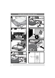
1.2.1 Figures<br />
The figures in these instructions for use are numbered<br />
1, 2, 3, etc.<br />
Components shown in the figures are marked A, B,<br />
C, etc.<br />
A reference to component C in figure 2 is written<br />
“2:C”.<br />
1.2.2 Headings<br />
The headings in these instructions for use are numbered<br />
in accordance with the following example:<br />
“1.3.1 General safety check” is a subheading to<br />
“1.3 Safety checks” and is included under this<br />
heading.<br />
When referring to headings, only the number of the<br />
heading is normally specified. E.g. “See 1.3.1”.<br />
ENGLISH<br />
2 DESCRIPTION<br />
2.1 Drive<br />
The machine has 4-wheel drive. The power from<br />
the engine to the drive wheels is transferred hydraulically.<br />
The engine drives an oil pump, which<br />
pumps oil through the rear and front axle drives.<br />
The front axle and rear axle are connected in series,<br />
which means that the front wheels and rear<br />
wheels are forced to rotate at the same speed.<br />
To make turning easier, both axles are equipped<br />
with differential.<br />
Front-mounted implements are powered via drive<br />
belts.<br />
2.2 Steering<br />
The machine is articulated. This means that the<br />
chassis is divided into a front and a rear section,<br />
which can be turned in relation to each other.<br />
The articulated steering means that the machine<br />
can turn around trees and other obstacles with an<br />
extremely small turning radius.<br />
2.3 Safety system<br />
The machine is equipped with an electrical safety<br />
system. The safety system interrupts certain activities<br />
that can entail a danger of incorrect manoeuvres.<br />
For example, the engine cannot be started if<br />
the clutch-parking brake pedal is depressed.<br />
The operation of the safety system must<br />
always be checked every time before<br />
use.<br />
2.4 Controls<br />
2.4.1 Implement lifter, mechanical (3:C)<br />
(Pro16)<br />
To switch between working position and transport<br />
position:<br />
1. Depress the pedal fully.<br />
2. Release the pedal slowly.<br />
2.4.2 Implement lifter, hydraulic (5:M)<br />
(Pro20, Pro25, Pro Svan)<br />
The hydraulic implement lifter only<br />
works when the engine is running, and is<br />
controlled with the switch (5:M).<br />
The switch has the following three positions:<br />
• Floating position. Press the front part of the<br />
switch. The switch locks in the pressed position<br />
and the implement is lowered until it reaches its<br />
floating position.<br />
Floating position means that the implement always<br />
rests with the same pressure against the<br />
ground and can follow the ground’s contours.<br />
Floating position should be used when working.