STIGA PARK
STIGA PARK
STIGA PARK

You also want an ePaper? Increase the reach of your titles
YUMPU automatically turns print PDFs into web optimized ePapers that Google loves.
BRUKSANVISNING SV ....8<br />
KÄYTTÖOHJEET FI ...19<br />
BRUGSANVISNING DA..30<br />
BRUKSANVISNING NO .41<br />
GEBRAUCHSANWEISUNG DE...52<br />
INSTRUCTIONS FOR USE EN...64<br />
MODE D’EMPLOI FR....75<br />
GEBRUIKSAANWIJZING NL...86<br />
8211-0540-02<br />
<strong>STIGA</strong> <strong>PARK</strong><br />
4WD<br />
PRO 25<br />
PRO 20<br />
PRO 16<br />
PRO Svan
2<br />
1<br />
3<br />
5<br />
A<br />
B<br />
C<br />
G<br />
N<br />
O<br />
S T<br />
D<br />
E<br />
Pro20 Pro25<br />
Pro Svan<br />
H I J K L<br />
M<br />
F<br />
2<br />
4<br />
6<br />
P<br />
Q<br />
R<br />
G<br />
N<br />
Pro16<br />
H I J K
7<br />
9<br />
U<br />
V<br />
11<br />
W<br />
W<br />
Pro16 Pro20<br />
Pro Svan<br />
8<br />
Max<br />
10<br />
12<br />
Pro25<br />
Pro25<br />
W<br />
X<br />
3
4<br />
13<br />
15<br />
17<br />
Z<br />
Y<br />
10 Ampere<br />
Pro16 Pro20<br />
Pro Svan<br />
Y<br />
14<br />
16<br />
B<br />
A<br />
0<br />
1<br />
18<br />
Pro25<br />
Pro16 Pro20<br />
Z<br />
Y
19<br />
21<br />
23<br />
Z<br />
Pro25<br />
20<br />
22<br />
24<br />
F<br />
G<br />
H<br />
5
25<br />
27<br />
29<br />
6<br />
B E<br />
A<br />
Pro25<br />
E<br />
C<br />
D<br />
26<br />
28<br />
30<br />
Pro16 Pro20<br />
A<br />
Pro Svan<br />
B
31<br />
33<br />
32<br />
7
64<br />
EN<br />
1 GENERAL<br />
This symbol indicates WARNING. Serious<br />
personal injury and/or damage to<br />
property may result if the instructions<br />
are not followed carefully.<br />
You must read these instructions for use<br />
and the accompanying pamphlet<br />
“SAFETY INSTRUCTIONS” carefully,<br />
before starting up the machine.<br />
1.1 SYMBOLS<br />
The following symbols appear on the machine.<br />
They are there to remind you of the care and attention<br />
required during use and maintenance.<br />
This is what the symbols mean:<br />
Warning!<br />
Read the instruction manual and the safety<br />
manual before using the machine.<br />
Warning!<br />
Watch out for discarded objects. Keep onlookers<br />
away.<br />
Warning!<br />
Always wear hearing protectors.<br />
Warning!<br />
This machine is not designed to be driven<br />
on public roads.<br />
Warning!<br />
The machine, equipped with original accessories,<br />
must not be driven in any direction<br />
on slopes with a gradient greater than<br />
10º.<br />
Warning!<br />
Risk of crushing injuries. Keep hands and<br />
feet well away from the articulated steering<br />
joint.<br />
Warning!<br />
Risk of burn injuries. Do not touch the silencer/catalytic<br />
converter.<br />
1.2 References<br />
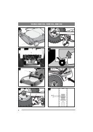
1.2.1 Figures<br />
The figures in these instructions for use are numbered<br />
1, 2, 3, etc.<br />
Components shown in the figures are marked A, B,<br />
C, etc.<br />
A reference to component C in figure 2 is written<br />
“2:C”.<br />
1.2.2 Headings<br />
The headings in these instructions for use are numbered<br />
in accordance with the following example:<br />
“1.3.1 General safety check” is a subheading to<br />
“1.3 Safety checks” and is included under this<br />
heading.<br />
When referring to headings, only the number of the<br />
heading is normally specified. E.g. “See 1.3.1”.<br />
ENGLISH<br />
2 DESCRIPTION<br />
2.1 Drive<br />
The machine has 4-wheel drive. The power from<br />
the engine to the drive wheels is transferred hydraulically.<br />
The engine drives an oil pump, which<br />
pumps oil through the rear and front axle drives.<br />
The front axle and rear axle are connected in series,<br />
which means that the front wheels and rear<br />
wheels are forced to rotate at the same speed.<br />
To make turning easier, both axles are equipped<br />
with differential.<br />
Front-mounted implements are powered via drive<br />
belts.<br />
2.2 Steering<br />
The machine is articulated. This means that the<br />
chassis is divided into a front and a rear section,<br />
which can be turned in relation to each other.<br />
The articulated steering means that the machine<br />
can turn around trees and other obstacles with an<br />
extremely small turning radius.<br />
2.3 Safety system<br />
The machine is equipped with an electrical safety<br />
system. The safety system interrupts certain activities<br />
that can entail a danger of incorrect manoeuvres.<br />
For example, the engine cannot be started if<br />
the clutch-parking brake pedal is depressed.<br />
The operation of the safety system must<br />
always be checked every time before<br />
use.<br />
2.4 Controls<br />
2.4.1 Implement lifter, mechanical (3:C)<br />
(Pro16)<br />
To switch between working position and transport<br />
position:<br />
1. Depress the pedal fully.<br />
2. Release the pedal slowly.<br />
2.4.2 Implement lifter, hydraulic (5:M)<br />
(Pro20, Pro25, Pro Svan)<br />
The hydraulic implement lifter only<br />
works when the engine is running, and is<br />
controlled with the switch (5:M).<br />
The switch has the following three positions:<br />
• Floating position. Press the front part of the<br />
switch. The switch locks in the pressed position<br />
and the implement is lowered until it reaches its<br />
floating position.<br />
Floating position means that the implement always<br />
rests with the same pressure against the<br />
ground and can follow the ground’s contours.<br />
Floating position should be used when working.
• Lifting. Press the rear part of the switch until<br />
the implement is in its highest position (transport<br />
position). Then release the switch and the<br />
height is locked in transport position.<br />
• Locking in transport position. The switch has<br />
reverted to neutral position after lifting. The implement<br />
is locked in transport position.<br />
NOTE! The hydraulic implement lifter must be<br />
in floating position in order for the power takeoff<br />
to be engaged.<br />
NOTE! The power take-off cannot be engaged<br />
when the parking brake is activated.<br />
2.4.3 Clutch-parking brake (3:B)<br />
Never press the pedal while driving.<br />
There is a risk of overheating in the<br />
power transmission.<br />
The pedal (3:B) has the following<br />
three positions:<br />
• Released. The clutch is not activated. The parking<br />
brake is not activated.<br />
• Depressed halfway. Forward drive disengaged.<br />
The parking brake is not activated.<br />
• Pressed down. Forward drive disengaged. The<br />
parking brake is fully activated but not locked.<br />
•<br />
2.4.4 Inhibitor, parking brake (3:A)<br />
The inhibitor locks the “clutch-brake”<br />
pedal in the depressed position. This function<br />
is used to lock the machine on slopes,<br />
during transport, etc., when the engine is<br />
not running.<br />
The parking brake must always be released<br />
during operation.<br />
Locking:<br />
1. Depress the pedal (3:B) fully.<br />
2. Move the inhibitor (3:A) to the right.<br />
3. Release the pedal (3:B).<br />
4. Release the inhibitor (3:A).<br />
Unlocking:<br />
Press and release the pedal (3:B).<br />
ENGLISH EN<br />
2.4.5 Driving-service brake (3:F)<br />
The pedal (3:F) determines the gearing ratio between<br />
the engine and the drive wheels (= the<br />
speed). When the pedal is released, the service<br />
brake is activated.<br />
1. Press the pedal forward –<br />
the machine moves forward.<br />
2. No load on the pedal – the machine<br />
is stationary.<br />
3. Press the pedal backward –<br />
the machine reverses.<br />
4. Reduce the pressure on the<br />
pedal – the machine brakes.<br />
2.4.6 Steering wheel (3:D)<br />
The height of the steering wheel is infinitely adjustable.<br />
Undo the adjustment knob (3:E) on the<br />
steering column and raise or lower the steering<br />
wheel to the desired position. Tighten.<br />
Do not adjust the steering wheel during<br />
operation.<br />
Never turn the steering wheel when the<br />
machine is stationary with a lowered<br />
implement. There is a risk of abnormal<br />
loads on the servo and steering mechanisms.<br />
2.4.7 Throttle control (4,5:G)<br />
Control for setting the engine’s revs.<br />
1. Full throttle – when the machine is in<br />
operation, full throttle should always be<br />
used.<br />
2. Idling.<br />
2.4.8 Choke control (4,5:H)<br />
A pull-type control to choke the engine when starting<br />
from cold.<br />
1. Control fully pulled out – choke valve<br />
in carburettor closed. For starting cold engine.<br />
2. Control pushed in – choke valve open.<br />
For starting warm engine and when operating<br />
the machine.<br />
Never operate the machine with the choke<br />
pulled out when the engine is warm.<br />
2.4.9 Ignition lock/headlight (4,5:I)<br />
The ignition lock is used for starting and stopping<br />
the engine. The ignition lock is also the switch for<br />
the headlight.<br />
65
66<br />
EN<br />
Do not leave the machine with the key<br />
in position 2 or 3. There is a fire risk,<br />
fuel can run into the engine through the<br />
carburettor, and there is a risk of the<br />
battery being discharged and damaged.<br />
Four positions:<br />
1. Stop position – the engine is short-circuited.<br />
The key can be removed.<br />
2. Operating position – headlight activated.<br />
3. Operating position – headlight not activated.<br />
4. Start position – the electric start motor<br />
is activated when the key is turned to the<br />
spring-loaded start position. Once the engine<br />
has started, let the key return to operating<br />
position 3.<br />
Turn the key to position 2 to light the<br />
headlight.<br />
2.4.10 Power take-off (4,5:K)<br />
Switch for engaging/disengaging the electromagnetic<br />
power take-off for operating front-mounted<br />
accessories. Two positions:<br />
1. Press the front part of the switch – the<br />
power take-off is engaged. The symbol<br />
will light up.<br />
2. Press the rear part of the switch – the<br />
power take-off is disengaged.<br />
2.4.11 Hour meter (2:P)<br />
Indicates the number of working hours. Only<br />
works when the engine is running.<br />
2.4.12 Cruise control (5, 6:N)<br />
A switch for activating the cruise control. The<br />
cruise control locks the pedal (3:F) in the desired<br />
position.<br />
1. Press down the pedal (3:F) until the desired<br />
speed is obtained. Then press the<br />
front part of the switch to activate the<br />
cruise control. The symbol will light up.<br />
2. Disengage the cruise control by releasing<br />
it with the pedal (3:B) or pressing the<br />
rear part of the switch.<br />
2.4.13 Cutting height adjustment (4,5:J)<br />
The machine is equipped with a control for using<br />
the cutting deck with electrical cutting height adjustment.<br />
The switch is used to adjust the cutting<br />
height in continuously variable positions.<br />
The cutting deck is connected to the contact (2:Q).<br />
ENGLISH<br />
2.4.14Rear Rake (5:L)<br />
(Pro20, Pro25, Pro Svan)<br />
The machine is fitted with a control for electrical<br />
adjustment of a rear rake (available as an<br />
accessory).<br />
The switch is used to raise and lower the<br />
rear rake.<br />
Cables for connecting the rear rake are found at the<br />
rear of the machine, to the left of the upper side of<br />
the bumper. (Pro16 is prepared for a rear rake,<br />
cables routed).<br />
2.4.15 Sand spreader (6:O)<br />
(Pro20, Pro25, Pro Svan)<br />
The machine has been designed for electrical adjustment<br />
of a sand spreader (accessory).<br />
12V<br />
The switch is used to start and stop the<br />
spreader.<br />
Cables for connecting the sand spreader are at the<br />
rear of the machine. (Pro16 is prepared for a sand<br />
spreader, cables routed).<br />
2.4.16 Clutch release lever (6:R)<br />
A lever for disengaging the variable transmission.<br />
Enables the machine to be moved by hand without<br />
the help of the engine. Two positions:<br />
1. Lever out – transmission engaged<br />
for normal operation.<br />
There is an audible click when<br />
the lever locks in the outer position.<br />
2. Lever in – transmission disengaged.<br />
The machine can be<br />
moved by hand.<br />
The machine may not be towed over long distances<br />
or at high speeds. The transmission could be damaged.<br />
2.4.17 Seat (1:T)<br />
The seat can be folded and adjusted frontrear.<br />
The seat can be adjusted as follows:<br />
1. Move the control lever (1:T) upwards.<br />
2. Set the seat to the desired position.<br />
3. Release the control lever (1:S) to lock<br />
the seat.<br />
The seat is equipped with a safety switch that is<br />
connected to the machine’s safety system. This<br />
means that certain dangerous activities are not possible<br />
when there is nobody sitting on the seat. Also<br />
see 4.3.2.<br />
2.4.18 Engine casing (7:U)<br />
In order to access the fuel cock, battery<br />
and engine, the machine has an engine<br />
casing that can be opened. The engine casing<br />
is locked with a rubber strap.
The engine casing is opened as follows:<br />
1. Undo the rubber strap (7:V) at the front edge of<br />
the casing.<br />
2. Carefully lift the engine casing back.<br />
Close in the reverse order.<br />
The machine may not be operated unless<br />
the engine casing is closed and<br />
locked. Risk of burns and crushing injuries.<br />
3 AREAS OF USE<br />
The machine may only be used for the following<br />
tasks using the genuine <strong>STIGA</strong> accessories stated.<br />
Work Accessories, <strong>STIGA</strong> genuine<br />
Mowing Using mowing decks:<br />
107 M, 107 M HD, 107 M HD<br />
El, 121 M, 121 M El, 125 Combi<br />
Pro, 125 Combi Pro El and with<br />
flail mower.<br />
Sweeping Using brush unit or collector<br />
brush unit. The use of a dust<br />
guard is recommended with the<br />
first option.<br />
Snow clearance Using snow blade or snow<br />
thrower Snow chains are recommended.<br />
Grass clipping and Using towed collector 30" or<br />
leaf collection 42".<br />
Grass and leaf Using dump cart Standard, Maxi<br />
transport or Combi.<br />
Sand spreading Using sand spreader. Can also<br />
be used for spreading salt. Snow<br />
chains are recommended.<br />
Weeding on gravel Using front-mounted hoe.<br />
paths<br />
Lawn edge trim- Using edge trimmer.<br />
ming<br />
Moss scarification Using moss scarifier.<br />
The maximum vertical load on the towing hitch<br />
must not exceed 100 N.<br />
The maximum over-run load on the towing hitch<br />
from towed accessories must not exceed 500 N.<br />
NOTE! Before using a trailer – contact your insurance<br />
company.<br />
NOTE! This machine is not intended to be driven<br />
on public roads.<br />
ENGLISH EN<br />
4 STARTING AND OPERATION<br />
The machine may not be operated unless<br />
the engine casing is closed and<br />
locked. Risk of burns and crushing injuries.<br />
4.1 Filling with petrol<br />
Always use lead-free petrol. You must never use 2stroke<br />
petrol mixed with oil.<br />
The tank holds 14 litres. The level can easily be<br />
read through the transparent tank.<br />
NOTE! Ordinary lead-free petrol is a perishable<br />
and must not be stored for more than 30 days.<br />
Environmental petrol can be used, i.e. alkylate<br />
petrol. This type of petrol has a composition that is<br />
less harmful for people and nature.<br />
Petrol is highly inflammable. Always<br />
store fuel in containers that are made<br />
especially for this purpose.<br />
Only fill or top up with petrol outdoors,<br />
and never smoke when filling or topping<br />
up. Fill up with fuel before starting<br />
the engine. Never remove the filler cap<br />
or fill with petrol while the engine is<br />
running or still warm.<br />
Never completely fill the petrol tank. Leave an<br />
empty space (= at least the entire filler tube plus 1<br />
- 2 cm at the top of the tank) to allow the petrol to<br />
expand when it warms up without overflowing.<br />
See fig. 8.<br />
4.2 Checking the engine oil level<br />
On delivery, the Pro 16 and Pro 20 (Briggs & Stratton)<br />
are filled with SAE 30 oil.<br />
On delivery, the Pro 25 (Kohler) and Pro Svan<br />
(Honda) are filled with SAE 10W-40 oil.<br />
Check the oil level every time before using to<br />
ensure it is correct. The machine should be<br />
standing on level ground.<br />
Wipe around the dipstick. Unscrew and<br />
pull it up. Wipe the dipstick.<br />
Pro 16, Pro 20, Pro25:<br />
Push the dipstick down completely and screw into<br />
place.<br />
Unscrew and pull the dipstick up again. Read off<br />
the oil level.<br />
Pro Svan:<br />
Push the dipstick down completely without screwing<br />
it into place. Pull it up again and read off the oil<br />
level.<br />
Top up with oil to the “FULL” mark if the oil level<br />
is below this mark. See fig. 9-11.<br />
67
68<br />
EN<br />
The oil level must never exceed the “FULL” mark.<br />
This results in the engine overheating. If the oil<br />
level exceeds the “FULL” mark, the oil must be<br />
drained until the correct level is achieved.<br />
4.3 Safety checks<br />
Check that the results of the safety checks below<br />
are achieved when testing the machine in question.<br />
The safety checks must always be carried<br />
out every time before use.<br />
If any of the results below is not<br />
achieved, the machine must not be<br />
used! Take the machine to a service<br />
workshop for repair.<br />
4.3.1 General safety check<br />
Object Result<br />
Fuel lines and con- No leaks.<br />
nections.<br />
Electrical cables. All insulation intact.<br />
No mechanical damage.<br />
Exhaust system. No leaks at connections.<br />
All screws tightened.<br />
Oil lines No leaks. No damage.<br />
Drive the machine The machine will stop.<br />
forwards/backwards<br />
and release<br />
the driving-service<br />
brake pedal.<br />
Test driving No abnormal vibrations.<br />
No abnormal sound.<br />
4.3.2 Electrical safety check<br />
The operation of the safety system<br />
should always be checked every time<br />
before use.<br />
Status Action Result<br />
The clutch-brake<br />
pedal is not<br />
depressed.<br />
The power take-off<br />
is not activated.<br />
The clutch-brake<br />
pedal is depressed.<br />
The power take-off<br />
is activated.<br />
Engine running.<br />
The power take-off<br />
is activated.<br />
Try to start. The engine<br />
will not start.<br />
The driver gets up<br />
from the seat.<br />
The driver gets up<br />
from the seat.<br />
Engine running. Remove fuse 10<br />
A.<br />
See fig. 13.<br />
The engine<br />
will not start.<br />
The power<br />
take-off will<br />
be disen-<br />
gaged.<br />
The engine<br />
will stop.<br />
ENGLISH<br />
Status Action Result<br />
Cruise control activated.<br />
The driver gets up<br />
from the seat.<br />
The cruise<br />
control will<br />
be disen-<br />
gaged.<br />
Cruise control acti- The clutch-brake The cruise<br />
vated.<br />
pedal is depressed. control will<br />
be disengaged.<br />
The switch for the Try to engage the It will not be<br />
implement lifter is power take-off. possible to<br />
in neutral position.<br />
engage the<br />
(not Pro16)<br />
power takeoff.<br />
4.4 Start<br />
1. Open the fuel cock. See 14.<br />
2. Check that the spark plug cable(s) is/are installed<br />
on the spark plug(s).<br />
3. Check to make sure that the power take-off is<br />
disengaged.<br />
4. Do not keep your foot on the drive pedal (3:F).<br />
5. Put the throttle control at full throttle.<br />
Starting cold engine – pull the choke control out<br />
fully.<br />
Starting warm engine – the choke control<br />
should be pressed in.<br />
6. Depress the clutch-brake pedal (3:B) fully.<br />
7. Turn the ignition key and start the engine.<br />
8 Once the engine has started, push the choke<br />
control in gradually if it has been used.<br />
9. When starting from cold, do not make the machine<br />
work under load immediately, but let the<br />
engine run for a few minutes first. This will allow<br />
the oil to warm up.<br />
When the machine is in operation, full throttle<br />
should always be used.<br />
4.5 Power assisted steering<br />
(Pro20, Pro25, Pro Svan)<br />
Power assisted steering means that power from the<br />
machine’s hydraulic system is supplied to the<br />
steering wheel movements. This makes the machine<br />
very easy to steer when the engine is operating<br />
at working revs (full throttle).<br />
The servo effect is reduced as the engine speed<br />
drops.<br />
4.6 Operating tips<br />
Always check that there is the correct volume of<br />
oil in the engine. This is particularly important<br />
when operating on slopes. See 4.2.
Be careful when driving on slopes. No<br />
sudden starting or stopping when driving<br />
up or down a slope. Never drive<br />
across a slope. Move from the top down<br />
or from the bottom to the top.<br />
The machine may not be driven on<br />
slopes greater than 10º in any direction.<br />
Reduce the speed on slopes and when<br />
making sharp turns in order to retain<br />
control and reduce the risk of tipping<br />
over.<br />
Do not turn the steering wheel to full<br />
lock when driving in top gear and at full<br />
throttle. The machine can easily topple<br />
over.<br />
Keep hands and fingers well away from<br />
articulated steering joint and seat<br />
bracket. Risk of crushing injuries. Never<br />
drive with the engine casing open.<br />
4.7 Stop<br />
Disengage the power take-off. Apply the parking<br />
brake.<br />
Allow the engine to idle 1-2 mins. Stop the engine<br />
by turning off the ignition key.<br />
Shut off the petrol cock. This is particularly important<br />
if the machine is to be transported on a trailer<br />
for example.<br />
If the machine is left unattended, remove<br />
the spark plug cable(s) and remove<br />
the ignition key.<br />
The engine may be very warm immediately<br />
after it is shut off. Do not touch the<br />
silencer, cylinder or cooling fins. This<br />
can cause burn injuries.<br />
4.8 Cleaning<br />
To reduce the risk of fire, keep the engine,<br />
silencer, battery and fuel tank free<br />
from grass, leaves and oil.<br />
To reduce the risk of fire, regularly<br />
check the machine for oil and/or fuel<br />
leakage.<br />
Clean the machine after each use. The following<br />
instructions apply for cleaning:<br />
• When washing the machine with water under<br />
high pressure, do not point the jet directly at<br />
axle seals, electrical components or hydraulic<br />
valves.<br />
• Do not spray water directly at the engine.<br />
• Clean the engine with a brush and/or compressed<br />
air.<br />
• Clean the engine’s cooling air intake (9-11:W).<br />
• Only Pro25: Clean the oil cooler (12:X).<br />
ENGLISH EN<br />
5 MAINTENANCE<br />
5.1 Service programme<br />
In order to keep the machine in good condition as<br />
regards reliability and operational safety as well as<br />
from an environmental perspective, <strong>STIGA</strong>’s Service<br />
programme should be followed.<br />
The contents of this programme can be found in<br />
the attached service log.<br />
Basic service must always be carried out by an authorised<br />
workshop.<br />
First service and intermediate service should be<br />
carried out by an authorised workshop, but can<br />
also be carried out by the user. The content of this<br />
can be found in the service log and the actions are<br />
described under “4 STARTING AND OPERA-<br />
TION” as well as below.<br />
Servicing carried out at an authorised workshop<br />
guarantees professional work using genuine spare<br />
parts.<br />
At each basic service and intermediate service carried<br />
out at an authorised workshop, the service log<br />
is stamped. A service log presenting these services<br />
is a valuable document that improves the machine’s<br />
second-hand value.<br />
5.2 Preparation<br />
All service and all maintenance must be carried out<br />
on a stationary machine with the engine switched<br />
off.<br />
Prevent the machine from rolling by always<br />
applying the parking brake.<br />
Stop the engine.<br />
Prevent unintentional starting of the<br />
engine by disconnecting the spark plug<br />
cable(s) from the spark plug(s) and removing<br />
the ignition key.<br />
5.3 Tyre pressure<br />
Adjust the air pressure in the tyres as follows:<br />
Front: 0.6 bar (9 psi).<br />
Rear: 0.4 bar (6 psi).<br />
5.4 Changing engine oil, filter<br />
This section contains tables covering the different<br />
engines that are included in <strong>STIGA</strong>’s Pro range. To<br />
facilitate reading, mark the data that applies to the<br />
relevant machine/engine.<br />
69
70<br />
EN<br />
5.4.1 Change intervals<br />
The table below states hours of operation and calendar<br />
months. Carry out the relevant action at<br />
whichever occurs first.<br />
Machine<br />
1st time Then at<br />
intervals of<br />
Pro16 Pro20 (B&S) Hours of operation/Calendar<br />
months<br />
Changing the oil<br />
5 hours<br />
50 hours/<br />
12 months<br />
Replacing the filter. - 100 hours<br />
Pro25 (Kohler) Hours of operation/Calendar<br />
months<br />
Changing the oil - 100 hours<br />
Replacing the filter. - 200 hours<br />
Pro Svan (Honda) Hours of operation/Calendar<br />
months<br />
Changing the oil 20 hours/ 100 hours/<br />
1 month 6 months<br />
Replacing the filter.<br />
-<br />
100 hours/<br />
6 months<br />
Change the oil more frequently if the engine has to<br />
operate in demanding conditions or if the ambient<br />
temperature is high.<br />
5.4.2 Engine Oil<br />
Use synthetic oil according to the table below.<br />
Machine Oil<br />
Pro16 Pro20 (B&S) Grade Service<br />
class<br />
All temperatures SAE 10W-30 SF<br />
Below -18° C SAE 5W-30 or higher<br />
Above 0° C SAE30<br />
Pro25 (Kohler) Grade Service<br />
class<br />
Above -18° C SAE 10W-30 SG<br />
Below 0° C SAE 5W-20/30 or higher<br />
Pro Svan (Honda) Grade Service<br />
class<br />
All temperatures SAE 10W-30 SJ<br />
Below 0° C SAE 5W-30 or higher<br />
Above 10° C SAE30<br />
Use oil without any additives.<br />
Do not fill with too much oil. This can cause the<br />
engine to overheat.<br />
Change oil when the engine is warm.<br />
ENGLISH<br />
The engine oil may be very hot if it is<br />
drained off directly after the engine is<br />
shut off. Therefore allow the engine to<br />
cool a few minutes before draining the<br />
oil.<br />
1. Attach the clamp on the oil drainage hose. Use<br />
a polygrip or similar. See fig. 15-17:Y.<br />
2. Move the clamp up 3-4 cm on the oil drainage<br />
hose and pull out the plug.<br />
3. Collect the oil in a collection vessel.<br />
NOTE! Do not spill any oil on the drive belts.<br />
4. Hand in the oil for disposal in accordance with<br />
local provisions.<br />
5. Install the oil drainage plug and move the clamp<br />
back so that it clamps above the plug.<br />
6. If the oil filter is to be replaced, see 5.4.3 below<br />
before continuing.<br />
7. Remove the dipstick and fill with new oil.<br />
Oil quantity:<br />
Machine Oil quantity, approximately<br />
No filter Filter replace-<br />
replacement ment<br />
Pro16, Pro20 1.6 litres 1.7 litres<br />
Pro25 2.0 litres 2.1 litres<br />
Pro Svan 0.9 litres 1.05 litres<br />
8. After filling up the oil, start the engine and idle<br />
for 30 seconds.<br />
9. Check to see if there is any oil leakage.<br />
10.Stop the engine. Wait for 30 seconds and then<br />
check the oil level in accordance with 4.2.<br />
5.4.3 Oil filter<br />
First drain the engine oil and install the oil drainage<br />
plug as described above. Then replace the oil<br />
filter as follows:<br />
Pro 16, Pro 20, Pro Svan:<br />
1. Clean the area around the filter and dismantle<br />
the filter.<br />
2. Moisten the new filter’s gasket with oil.<br />
3. Install the filter. First screw in the filter so that<br />
the gasket comes into contact with the engine.<br />
Then screw in the filter a further 1/2-3/4 turn.<br />
4. Continue with point 7 in accordance with 5.4.2<br />
Engine Oil above.<br />
Pro 25:<br />
1. Clean the area around the filter and dismantle<br />
the filter.<br />
2. Place the new filter with the hole facing upwards<br />
in a vessel.<br />
3. Fill up with the new engine oil through the hole<br />
in the filter until the level reaches the bottom of<br />
the thread.<br />
4. Wait 1-2 minutes so that the oil is absorbed by<br />
the filter material.<br />
5. Moisten the filter’s gasket with oil.
6. Install the filter. First screw in the filter so that<br />
the gasket comes into contact with the engine.<br />
Then screw in the filter a further 2/3-1 turn.<br />
7. Continue with point 7 in accordance with 5.4.2<br />
Engine Oil above.<br />
5.5 Fuel filter<br />
Pro 16, Pro 20 (Briggs & Stratton) and Pro Svan<br />
(Honda)<br />
Replace the fuel filter every season. See fig. 17-<br />
18:Z.<br />
Pro 25 (Kohler)<br />
Replace the fuel filter after 1,500 hours of operation.<br />
See fig. 19:Z.<br />
Check for fuel leaks once the new filter has been<br />
installed.<br />
5.6 Transmission, oil filter<br />
The oil and the filter in the hydraulic power transmission<br />
must be checked/adjusted or replaced at<br />
intervals according to the table below.<br />
1st time Then at<br />
Action<br />
interval<br />
Hours of operation<br />
Check – adjusting level. - 50<br />
Changing oil.<br />
Cleaning tank filter.<br />
5 200<br />
Replace filter in the hydraulic<br />
circuit. Pro20, Pro25<br />
5 200<br />
Oil type: Synthetic oil 5W-50.<br />
Oil volume at change: approx. 4.2 litres.<br />
5.6.1 Check – adjustment<br />
1. Place the machine on a flat surface.<br />
2. Read off the oil level in the reservoir. See fig.<br />
20. The level should be level with the line.<br />
3. If necessary, top up with more oil.<br />
5.6.2 Draining<br />
1. Operate the machine at varying speeds for 10-<br />
20 minutes in order to warm up the transmission<br />
oil.<br />
2. Open the drive shafts’ valves in accordance<br />
with fig. 21.<br />
3. Place one collection trough under the rear axle<br />
and one under the front axle.<br />
4. Remove 2 drainage plugs from each axle. Use a<br />
12 mm socket wrench. See fig. 22.<br />
5. Remove the filler cap from the oil tank.<br />
6. Only Pro20, Pro25 and Pro Svan: Clean the area<br />
around the hydraulic circuit’s filter and dismantle<br />
the filter. See fig. 16:A.<br />
7. Allow all the oil to run out into the collection<br />
trough.<br />
ENGLISH EN<br />
8. Draw out the oil from the deeper section of the<br />
reservoir using an oil extractor. See fig. 20.<br />
9. Hand in the oil for disposal in accordance with<br />
local provisions.<br />
5.6.3 Cleaning tank filter<br />
1. Press the filter casing (24:F)down into the upper<br />
section of the tank and move the casing forwards<br />
to the hole.<br />
2. Pull up the filter casing together with filter and<br />
spring.<br />
3. Pull the filter (24:G) out of the casing.<br />
4. Clean the filter with a suitable solvent and compressed<br />
air.<br />
5. Check that the rubber gasket (24:H) in the bottom<br />
of the filter is intact.<br />
6. Reinstall the filter and spring in the casing. Insert<br />
the filter until it snaps into position in the<br />
casing.<br />
7. Reinstall the unit in the tank. The upper part of<br />
the filter casing must snap into position in the<br />
slot in the upper section of the tank.<br />
5.6.4 Filling<br />
1. Check that the gaskets on the 4 drainage plugs<br />
are intact. See fig. 22. Reinstall the plugs. Tightening<br />
torque: 15-17 Nm.<br />
2. Only applies to Pro20, Pro25 and Pro Svan:<br />
Moisten the new filter’s gasket with oil and install<br />
the filter. See fig. 16:A.<br />
3. Fill the oil reservoir with the new oil.<br />
4. Check that the clutch release lever (6:R) is in<br />
the outer position (drive position).<br />
If the engine is to be run indoors, an exhaust<br />
extraction device must be connected<br />
to the engine’s exhaust pipe.<br />
5. Prepare a suitable vessel with the new oil.<br />
NOTE! The oil is sucked into the system very<br />
quickly. The reservoir must always be kept<br />
topped up. Under no circumstances may air<br />
be sucked in.<br />
6. Fill the oil reservoir with new oil.<br />
7. Start the engine and allow it to idle. Gradually<br />
top up the oil in the reservoir so that the level<br />
constantly reaches the mark.<br />
8. Reinstall the oil filler cap and close the engine<br />
casing.<br />
9. Reset the drive shafts’ valves in accordance<br />
with fig. 25.<br />
71
72<br />
EN<br />
10.Drive the machine 8-10 metres forwards and 8-<br />
10 metres backwards. If the machine has hydraulic<br />
power assisted steering, apply full steering<br />
lock at the same time.<br />
11.If the machine has a hydraulic implement lifter,<br />
raise and lower the lifter 3-4 times.<br />
12.Adjust the oil level in the reservoir.<br />
5.7 Belt transmissions<br />
After 5 hours of operation, check that all the belts<br />
are intact and undamaged.<br />
5.8 Steering<br />
The steering must be checked/adjusted after 5<br />
hours of operation and thereafter after 100 hours of<br />
operation.<br />
5.8.1 Checks<br />
Briefly turn the steering wheel back and forth.<br />
There must be no mechanical clearance in the<br />
steering chains.<br />
5.8.2 Adjustment<br />
Adjust the steering chains if required as follows:<br />
1. Put the machine in the straight-ahead position.<br />
2. Adjust the steering chains with the two nuts, located<br />
under the central point. See fig. 29.<br />
3. Adjust both nuts by the same amount until there<br />
is no clearance.<br />
4. Test drive the machine straight forwards and<br />
check that the steering wheel is not off centre.<br />
5. If the steering wheel is off centre, undo one nut<br />
and tighten the other.<br />
Do not over-tighten the steering chains. This will<br />
cause the steering to become heavy and will increase<br />
wear on the steering chains.<br />
5.9 Battery<br />
If acid comes into contact with the eyes<br />
or skin, this can cause serious injuries.<br />
If any part of the body has come into<br />
contact with acid, rinse immediately<br />
with copious amounts of water and seek<br />
medical assistance as soon as possible.<br />
The battery is a valve-regulated battery with 12 V<br />
nominal voltage. The battery fluid does not need to<br />
and cannot be checked or topped up. The only<br />
maintenance that is required is charging, for example<br />
after extended storage.<br />
The battery must be fully charged before<br />
being used for the first time. The<br />
battery must always be stored fully<br />
charged. If the battery is stored while<br />
discharged, serious damage will occur.<br />
5.9.1 Charging with the engine<br />
The battery can be charged using the engine’s generator<br />
as follows:<br />
ENGLISH<br />
1. Install the battery in the machine as shown below.<br />
2. Place the machine outdoors or install an extraction<br />
device for the exhaust fumes.<br />
3. Start the engine according to the instructions in<br />
the user guide.<br />
4. Allow the engine to run continuously for 45<br />
minutes.<br />
5. Stop the engine. The battery will now be fully<br />
charged.<br />
5.9.2 Charging using battery charger<br />
When charging using a battery charger, a battery<br />
charger with constant voltage must be used.<br />
Contact your dealer to purchase a battery charger<br />
with constant voltage.<br />
The battery can be damaged if a standard type<br />
battery charger is used.<br />
5.9.3 Removal/Installation<br />
The battery is placed under the tank. To access the<br />
battery, first dismantle the fuel tank as follows:<br />
1. Open the engine casing.<br />
2. Close the fuel cock, see 14.<br />
3. Unscrew the two wing nuts (16:B) and remove<br />
the clamps.<br />
4. Carefully lift up the petrol tank.<br />
During removal/installation of the battery, the following<br />
applies regarding connection of the cables:<br />
• During removal. First disconnect the black cable<br />
from the battery’s negative terminal (-).<br />
Then disconnect the red cable from the battery’s<br />
positive terminal (-).<br />
• During installation. First connect the red cable<br />
to the battery’s positive terminal (+). Then connect<br />
the black cable to the battery’s negative terminal<br />
(-).<br />
If the cables are disconnected/connected<br />
in the wrong order, there is a risk of<br />
a short-circuit and damage to the battery.<br />
If the cables are interchanged, the generator<br />
and the battery will be damaged.<br />
The engine must never be driven with<br />
the battery disconnected. There is a risk<br />
of serious damage to the generator and<br />
the electrical system.<br />
When the battery has been rectified, install the fuel<br />
tank as follows:<br />
Check that the petrol hose is not<br />
clamped against the hydraulic pump<br />
and does not come into contact with<br />
this. The hydraulic pump becomes very<br />
hot during operation. Risk of fire.
1. Place the petrol tank on the brackets. Check that<br />
the petrol hose is not touching the hydraulic<br />
pump.<br />
2. Install the clamps and tighten the wing nuts<br />
(16:B).<br />
5.9.4 Cleaning<br />
If the battery terminals are coated with oxide, they<br />
should be cleaned. Clean the battery terminals with<br />
a wire brush and lubricate them with terminal<br />
grease.<br />
5.10 Air filter, engine<br />
5.10.1 Air filter (Pro16, Pro20)<br />
The pre-filter (foam filter) must be cleaned/replaced<br />
after 25 hours of operation.<br />
The air filter (paper filter) must be cleaned/replaced<br />
after 100 hours of operation.<br />
NOTE! The filters should be cleaned/replaced<br />
more often if the machine operates on dusty<br />
ground.<br />
Remove/install the air filters as follows.<br />
1. Clean carefully around the air filter cover.<br />
2. Dismantle the air filter cover (26:A) by removing<br />
the two clamps.<br />
3. Dismantle the filter assembly (26:B). The prefilter<br />
is placed over the air filter. Make sure that<br />
no dirt gets into the carburettor. Clean the air filter<br />
housing.<br />
4. Clean the paper filter by tapping it gently<br />
against a flat surface. If the filter is very dirty,<br />
replace it.<br />
5. Clean the pre-filter. If the filter is very dirty, replace<br />
it.<br />
6. Assemble in the reverse order.<br />
Compressed air or petroleum-based solvents such<br />
as kerosene may not be used for cleaning the paper<br />
filter insert. This will damage the filter.<br />
5.10.2 Air filter (Pro25)<br />
The pre-filter (foam filter) must be cleaned after 25<br />
hours of operation.<br />
The air filter (paper filter) must be replaced after<br />
100 hours of operation.<br />
NOTE! The filters should be cleaned/replaced<br />
more often if the machine operates on dusty<br />
ground.<br />
Remove/install the air filters as follows.<br />
1. Clean carefully around the air filter cover.<br />
2. Dismantle the air filter cover (27:A) by undoing<br />
its screw (27:B).<br />
3. Dismantle the filters. The pre-filter (27:C) is<br />
placed over the air filter (27:D). Make sure that<br />
no dirt gets into the carburettor. Clean the air filter<br />
housing.<br />
ENGLISH EN<br />
4. Wash the pre-filter (27:C) in liquid detergent<br />
and water. Squeeze dry. Pour a little oil on the<br />
filter and squeeze in the oil.<br />
5. Assemble in the reverse order. Check that the<br />
rubber seal (27:E) is undamaged. Replace the<br />
seal if necessary.<br />
5.10.3Air filter (Pro Svan)<br />
Clean the air filter every 3 months or after every 50<br />
hours of operation, whichever comes first.<br />
Clean the paper filter insert once a year or after<br />
every 200 hours of operation, whichever comes<br />
first.<br />
Note! Both filters should be cleaned more often if<br />
the machine operates on dusty ground.<br />
1. Remove the protective cover of the air filter<br />
(fig. 28).<br />
2. Dismantle the paper filter insert and the foam<br />
pre-filter. Make sure that no dirt gets into the<br />
carburettor. Clean the air filter housing.<br />
3. Wash the pre-filter in liquid detergent and<br />
water. Squeeze dry. Pour a little oil on the filter<br />
and squeeze in the oil.<br />
4. Clean the paper filter insert as follows: Knock it<br />
lightly against a flat surface. If the filter is very<br />
dirty, change it.<br />
5. Assemble in the reverse order.<br />
Petroleum-based solvents such as kerosene may<br />
not be used for cleaning the paper filter insert.<br />
These solvents can destroy the filter.<br />
Do not use compressed air for cleaning the<br />
paper filter insert. The paper filter insert must<br />
not be oiled.<br />
5.11 Spark plug<br />
The spark plug(s) must be replaced every 200<br />
hours of operation (=at every other basic service).<br />
Use the spark plug key supplied.<br />
Before disconnecting the spark plug, clean around<br />
its mounting.<br />
Spark plug:<br />
Pro16, Pro20, Pro25: Champion RC12YC or<br />
equivalent.<br />
Pro Svan: NGK BPR5ES or DENSO W16EPR-U<br />
Electrode distance: 0.75 mm.<br />
5.12 Air intake<br />
See 9-11:W. The engine is air-cooled. A blocked<br />
cooling system can damage the engine. Clean the<br />
engine’s air intake after 50 hours of operation.<br />
More meticulous cleaning of the cooling system is<br />
carried out during each basic service.<br />
73
74<br />
EN<br />
5.13 Lubrication<br />
All lubrication points in accordance with the table<br />
below must be lubricated every 50 hours of operation<br />
as well as after every wash.<br />
Object Action Fig-<br />
Wheel bear- 2 grease nipples.<br />
ing Use a grease gun filled with<br />
universal grease. Pump until<br />
the grease emerges.<br />
Centre point 4 grease nipples.<br />
Use a grease gun filled with<br />
universal grease. Pump until<br />
the grease emerges.<br />
Steering<br />
chains<br />
Tensioning<br />
arms<br />
Control<br />
cables<br />
Brush the chains clean with a<br />
wire brush.<br />
Lubricate with universal<br />
chain spray.<br />
Lubricate the bearing points<br />
with an oil can when each<br />
control is activated.<br />
Ideally carried out by two<br />
people.<br />
Lubricate the cable ends with<br />
an oil can when each control<br />
is activated.<br />
Must be carried out by two<br />
people.<br />
5.14 Fuses<br />
If any of the faults listed below occurs, replace the<br />
relevant fuse. See fig. 13.<br />
Fault Fuse<br />
The engine does not start or starts and 10 A<br />
stops immediately. The battery is<br />
charged.<br />
Sand spreader and electrical cutting 20 A<br />
height adjustment do not work.<br />
All electrical functions are out of 30 A<br />
operation. The battery is charged.<br />
ENGLISH<br />
ure<br />
30<br />
31<br />
-<br />
32<br />
33<br />
6 PATENT - DESIGN REGISTRA-<br />
TION<br />
This machine or parts thereof is covered by the following<br />
patent and design registration:<br />
SE9901091-0, SE9901730-3, SE9401745-6,<br />
US595 7497, FR772384, DE69520215.4,<br />
GB772384, SE0301072-5, SE04/000239 (PCT),<br />
SE0401554-1.<br />
GGP reserves the right to make alterations to the<br />
product without prior notification.
www.stiga.com<br />
GGP Sweden AB · Box 1006 · SE-573 28 TRANÅS