FR60 FAMILY EMA-MB91FV460B-001 - Fujitsu
FR60 FAMILY EMA-MB91FV460B-001 - Fujitsu
FR60 FAMILY EMA-MB91FV460B-001 - Fujitsu
Create successful ePaper yourself
Turn your PDF publications into a flip-book with our unique Google optimized e-Paper software.
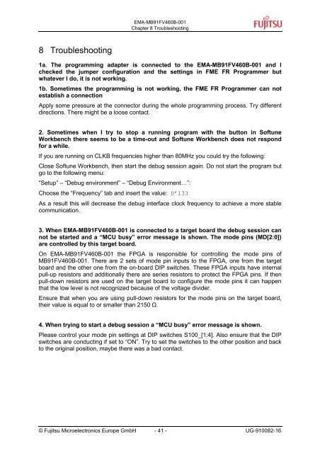
8 Troubleshooting<br />
<strong>EMA</strong>-<strong>MB91FV460B</strong>-<strong>001</strong><br />
Chapter 8 Troubleshooting<br />
1a. The programming adapter is connected to the <strong>EMA</strong>-<strong>MB91FV460B</strong>-<strong>001</strong> and I<br />
checked the jumper configuration and the settings in FME FR Programmer but<br />
whatever I do, it is not working.<br />
1b. Sometimes the programming is not working, the FME FR Programmer can not<br />
establish a connection<br />
Apply some pressure at the connector during the whole programming process. Try different<br />
directions. There might be a loose contact.<br />
2. Sometimes when I try to stop a running program with the button in Softune<br />
Workbench there seems to be a time-out and Softune Workbench does not respond<br />
for a while.<br />
If you are running on CLKB frequencies higher than 80MHz you could try the following:<br />
Close Softune Workbench, then start the debug session again. Do not start the program but<br />
go to the following menu:<br />
“Setup” – “Debug environment” – “Debug Environment…”:<br />
Choose the “Frequency” tab and insert the value: D’133<br />
As a result this will decrease the debug interface clock frequency to achieve a more stable<br />
communication.<br />
3. When <strong>EMA</strong>-<strong>MB91FV460B</strong>-<strong>001</strong> is connected to a target board the debug session can<br />
not be started and a “MCU busy” error message is shown. The mode pins (MD[2:0])<br />
are controlled by this target board.<br />
On <strong>EMA</strong>-<strong>MB91FV460B</strong>-<strong>001</strong> the FPGA is responsible for controlling the mode pins of<br />
<strong>MB91FV460B</strong>-<strong>001</strong>. There are 2 sets of mode pin inputs to the FPGA, one from the target<br />
board and the other one from the on-board DIP switches. These FPGA inputs have internal<br />
pull-up resistors and additionally there are series resistors to protect the FPGA pins. If then<br />
pull-down resistors are used on the target board to configure the mode pins it can happen<br />
that the low level is not recognized because of the voltage divider.<br />
Ensure that when you are using pull-down resistors for the mode pins on the target board,<br />
their value is equal to or smaller than 2150 Ω.<br />
4. When trying to start a debug session a “MCU busy” error message is shown.<br />
Please control your mode pin settings at DIP switches S100_[1:4]. Also ensure that the DIP<br />
switches are conducting if set to “ON”. Try to set the switches to the other position and back<br />
to the original position, maybe there was a bad contact.<br />
© <strong>Fujitsu</strong> Microelectronics Europe GmbH - 41 - UG-910082-16


