CMOS Baseline Process - Berkeley Microlab - University of ...
CMOS Baseline Process - Berkeley Microlab - University of ...
CMOS Baseline Process - Berkeley Microlab - University of ...

Create successful ePaper yourself
Turn your PDF publications into a flip-book with our unique Google optimized e-Paper software.
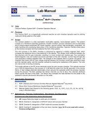
<strong>CMOS</strong> <strong>Baseline</strong> <strong>Process</strong><br />
in the<br />
UC <strong>Berkeley</strong> Micr<strong>of</strong>abrication Laboratory<br />
Report II.<br />
Laszlo Voros<br />
Electronics Research Laboratory<br />
<strong>University</strong> <strong>of</strong> California, <strong>Berkeley</strong><br />
December, 2000<br />
Abstract<br />
This is the second report describing the baseline <strong>CMOS</strong> process supported by the<br />
<strong>Berkeley</strong> <strong>Microlab</strong>. The baseline process defines “standard” process modules for a twinwell,<br />
1 µm <strong>CMOS</strong> technology with double poly-Si, double metal options. <strong>Process</strong> details<br />
are presented along with device characterization methodology and measurements.<br />
<strong>Process</strong> and device parameters are listed.
Table <strong>of</strong> Contents<br />
1. Introduction……………………………………………………………………………1<br />
2. <strong>Process</strong> Design for <strong>CMOS</strong>58-<strong>CMOS</strong>60 Runs..……………………………………….2<br />
2.1. <strong>Process</strong> Flow and Device Cross Sections……………………………………...…2<br />
2.2. Mask Layout……………………………………………………………………...2<br />
2.3. Run Schedules……………………………………………………………………8<br />
3. Test Results for <strong>CMOS</strong>58-<strong>CMOS</strong>60 Runs……………………………………………9<br />
3.1. SUPREM3 Simulations and Spreading Resistance Analysis…………………….9<br />
3.2. HP4145 Measurement Results…………………………………………………..12<br />
3.3. Autoprober Measurement Results………………………………………………15<br />
3.4. Design Parameters………………………………………………………………17<br />
3.5. Method and Measurement Conditions…………………………………………..18<br />
4. Future Work………………………………………………………………………….18<br />
5. References…………………………………………………………………………....19<br />
6. Appendices<br />
A Detailed <strong>Process</strong> Flow<br />
B Autoprober Computer Program<br />
2
List <strong>of</strong> Figures and Tables<br />
Figure 1a-f. Brief <strong>Process</strong> Flow and Cross Sections...………...………………………..4-6<br />
Figure 2. Arrangement <strong>of</strong> test structures within the scribe lane.…...……………………..7<br />
Figure 3. <strong>CMOS</strong> baseline schedule……………………………………………………….8<br />
Figure 4. SUPREM3 simulation results for areas under the gate oxide....………………10<br />
Figure 5. Experimental results for areas under the gate oxide…………………………...10<br />
Figure 6. SUPREM3 simulation results for source-drain areas………………………….11<br />
Figure 7. Experimental results source-drain areas……………………………………….11<br />
Figure 8. NMOS (W/L=10/1) drain current vs. drain voltage characteristics…………...12<br />
Figure 9. NMOS (W/L=10/1) drain current vs. gate voltage at varying substrate bias….12<br />
Figure 10. NMOS (W/L=10/1) sub threshold characteristics……………………………13<br />
Figure 11. NMOS (W/L=10/1) drain current vs. gate voltage in saturation mode………13<br />
Figure 12. PMOS (W/L=10/1) drain current vs. drain voltage characteristics…………..13<br />
Figure 13. PMOS (W/L=10/1) drain current vs. gate voltage at varying substrate bias...14<br />
Figure 14. PMOS (W/L=10/1) sub threshold characteristics……………………………14<br />
Figure 15. PMOS (W/L=10/1) drain current vs. gate voltage in saturation mode………14<br />
Figure 16. (a) NMOS threshold voltage distribution,<br />
(b) standard deviation corresponding to data points in (a)………………………16<br />
Figure 17. (a) PMOS threshold voltage distribution,<br />
(b) standard deviation corresponding to data points in (a)……………………....16<br />
Table 1. Ion Implantations………………………………………………………………...3<br />
Table 2. Lithography Steps and Mask Identification……………………………………...3<br />
Table 3. <strong>Process</strong> and Device Parameters Targets<br />
(extracted from W=10 µm, L=1 µm device)………………………………..……17<br />
3
1. Introduction<br />
The Micr<strong>of</strong>abrication Laboratory at the <strong>University</strong> <strong>of</strong> California, <strong>Berkeley</strong> has been<br />
supporting silicon MOS technology from the time the present VLSI facility was opened<br />
in 1983. [1,2] In 1992 a <strong>CMOS</strong> baseline was formally established, which has been<br />
running continuously since then. The baseline specifies standard process modules for<br />
VLSI operations, and provides test circuits and starting point for various research groups<br />
such as the <strong>Berkeley</strong> Sensor and Actuator Center (BSAC) and the <strong>Berkeley</strong> Computer<br />
Aided Manufacturing group. [3,4,5] The baseline <strong>CMOS</strong> process also supports data for<br />
VLSI process control, which is ensured by monitoring 21 equipment and maintaining<br />
performance at baseline specifications.<br />
The first baseline report [6] describes a 2 µm, n-well, double poly-Si, double metal<br />
<strong>CMOS</strong> process, which was subsequently developed into a twin-well, 1.3 µm, double<br />
poly-Si, double metal process. This report describes the latter, which shows good<br />
performance even for L=1 µm transistors. Included are the actual process and device<br />
parameters, simulation data, electrical measurements, and analytical test results. <strong>Process</strong><br />
flow can be found in Appendix A and the source code for parameter extraction is listed in<br />
Appendix B.<br />
1
2. <strong>Process</strong> Design for <strong>CMOS</strong>58-60 Run<br />
The <strong>Microlab</strong>’s 1.3 µm, twin-well, double poly-Si and double metal <strong>CMOS</strong> process was<br />
first developed in 1995. The process has 8 implantation steps and 14 lithography steps<br />
(Table 1. and Table 2.); however, the number <strong>of</strong> the masks applied is 12. The starting<br />
material is 24-36 Ω-cm p-type, wafer, on which 0.8 µm (the smallest) N- and P-<br />
channel MOSFETs can be fabricated with punch-through implants. The process also<br />
contains N-field and P-field implants. The baseline process and device parameter targets<br />
are shown in Table 3.<br />
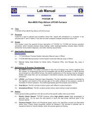
2.1 <strong>Process</strong> Flow and Cross Sections<br />
A brief processes flow with device cross sections are shown in Figure 1a-f. All process<br />
steps are accomplished in the <strong>Microlab</strong> except ion implantation, which is carried out at<br />
Ion Implant Services (Sunnyvale, CA). Detailed information can be found in the process<br />
outline in Appendix A, which includes the equipment used in the <strong>Microlab</strong> for <strong>CMOS</strong><br />
processing.<br />
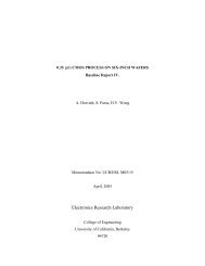
2.2 Mask layout<br />
The baseline utilizes a standard set <strong>of</strong> test structures for measurements, laid out in the<br />
scribe lane. [5] Participating groups are requested to include the scribe lane structures in<br />
their mask set, utilizing the drop-in area for their own devices, as shown in Figure 2.<br />
Runs <strong>CMOS</strong>58-60 used the full layout for BCAM application, as described in Ref.5.<br />
2
Table 1. Ion Implantations<br />
<strong>Process</strong> Step Species Energy (KeV) Dose (cm -2 )<br />
N-Well Implant Phosphorus 80 4x10 12<br />
P-Well Implant B11 80 3x10 12<br />
P-Well Field Implant B11 70 1.5x10 13<br />
N-Well Field Implant Phosphorus 40 3x10 12<br />
N-Channel Punchthrough and B11<br />
120 8x10<br />
Threshold Adjustment Implant B11<br />
30<br />
11<br />
1.9x10 12<br />
P-Channel Punchthrough and<br />
Phosphorus 190 1x10<br />
Threshold Adjustment Implant B11<br />
20<br />
12<br />
2.4x10 12<br />
N+ S/D Implant Arsenic 100 5x10 15<br />
P+ S/D Implant B11 20 5x10 15<br />
Table 2. Lithography Steps<br />
Lithography Step Mask Name Type Field Align. Step<br />
N-well Formation NWELL Chrome dark<br />
Active Area Definition ACTIVE Emulsion clear NWELL<br />
P-Well Field Implant Photo PFIELD<br />
(inv. <strong>of</strong> NWELL)<br />
Emulsion clear ACTIVE<br />
N-Well Field Implant Photo NWELL Chrome dark ACTIVE<br />
N-Channel Punch-through and PFIELD<br />
Emulsion clear ACTIVE<br />
Threshold Adjustment Photo (inv. <strong>of</strong> NWELL)<br />
P-Channel Punch-through and PVT Chrome dark ACTIVE<br />
Threshold Adjustment Photo<br />
Gate Definition POLY Emulsion clear ACTIVE<br />
Capacitor Formation 2 nd POLY Emulsion clear POLY<br />
N+ S/D Photo N+ S/D Chrome dark POLY<br />
P+ S/D Photo P+ S/D Emulsion clear POLY<br />
Contact Photo CONT Chrome dark POLY<br />
Metal Photo METAL1 Emulsion clear CONT<br />
VIA Photo VIA Chrome dark VIA<br />
Metal2 Photo METAL2 Emulsion clear METAL1<br />
3
P+<br />
Photoresist<br />
Nitride<br />
Fig.1-a. N-Well Formation<br />
Phosphorus<br />
Oxide<br />
N-well<br />
p-type Si 24-36 ohm-cm<br />
P+<br />
P-well<br />
Fig. 1-b. P-Well and Active Area Formation<br />
Boron<br />
P+<br />
Photoresist<br />
N-well<br />
4<br />
0. Bare Silicon Wafer<br />
1. Initial Oxidation: 30nm<br />
2. Nitride Deposition: 100nm<br />
3. N-Well Photo<br />
4. Nitride Etch<br />
5. N-Well Ion Implantation:<br />
Phosphorus, 80 KeV,<br />
4x10 12 /cm 2<br />
6. N-Well Cover Oxidation<br />
7. Nitride Removal<br />
8. P-Well Ion Implant<br />
9. Well Drive In<br />
10. Pad Oxidation/Nitride<br />
Deposition:<br />
30nm/100nm<br />
11. Active Area Photo<br />
12. Nitride Etch<br />
13. P-Well Field Implant<br />
Photo<br />
14. P-Well Field Ion<br />
Implant: B11, 70<br />
KeV, 1.5x10 13 /cm 2
P-well<br />
1) Phosphorus<br />
2) B11<br />
FOX<br />
Photoresist<br />
FOX FOX FOX FOX<br />
Photoresist<br />
N+<br />
P-well<br />
Fig. 1-c. LOCOS and Channel Implants<br />
P-type Si<br />
B11<br />
N-well<br />
Fig. 1-d. Gate Formation<br />
FOX FOX FOX FOX FOX<br />
N+ N+ N+ P+ P+ P+ P+<br />
N-well<br />
5<br />
15. N-Well Field Implant Photo<br />
16. N-Well Field Ion Implant:<br />
Phosphorus, 40 KeV,<br />
3x10 12 /cm 2<br />
17. Locos Oxidation: 650nm<br />
18. Nitride Removal and<br />
(Thin Oxide Removal)<br />
19. Sacrificial Oxide: 20nm<br />
20. P-Field Photo<br />
21. N-Channel Punch-through:<br />
B11, 120KeV, 8x10 11 /cm 2<br />
and Threshold Adjustment<br />
Implant: B11, 30 KeV,<br />
1.9x10 12 /cm 2<br />
22. N-Field Photo<br />
23. P-Channel Punch-through:<br />
Phosphorus, 190 KeV,<br />
1x10 12 /cm 2 and Threshold<br />
Adjustment Implant: B11,<br />
20 KeV, 2.4x10 12 /cm 2<br />
24. Gate Oxidation and<br />
Poly-Si Deposition<br />
25. Gate Poly Photo<br />
26. Gate Poly Etch<br />
27. Capacitor Oxidation<br />
28. Capacitor Poly Deposition<br />
29. Capacitor Photo/ Etch<br />
30. N+ S/D Photo<br />
31. N+ S/D Implant<br />
32. N+ S/D Anneal<br />
33. P+ S/D Photo<br />
34. P+ S/D Implant
FOX FOX FOX FOX FOX<br />
N+<br />
N+ N+ N+ P+ P+ P+ P+<br />
N+<br />
P-well<br />
Fig. 1-e. Contact and Metallization<br />
PSG<br />
SOG SOG<br />
PSG<br />
P-well<br />
N-well<br />
FOX FOX FOX FOX<br />
Fig. 1-f. Metal2 and Sinter<br />
N+ N+ N+ P+ P+ P+ P+<br />
N-well<br />
6<br />
FOX<br />
35. PSG Deposition &<br />
Post Densification<br />
36. Contact Mask<br />
37. Contact Etch<br />
37. Metallization<br />
38. Back Side Etch<br />
39. Metallization (6000A)<br />
40. Metal Mask<br />
41. Al Etch<br />
42. Sintering<br />
43. Testing<br />
44. Planerization and<br />
Dielectric Film<br />
Deposition<br />
45. VIA Photo<br />
46. Etch VIA<br />
47. Metal2 Metallization<br />
48. Metal2 Photo<br />
49. Etch Al<br />
50. Sintering<br />
51. Testing<br />
Final <strong>CMOS</strong> Device
Scribe Lane<br />
Scribe Lane<br />
Drop-in<br />
8.12 mm<br />
7.2 mm<br />
contact<br />
resistors<br />
split-cross<br />
bridge<br />
resistors<br />
Individual MOSFETs<br />
Scribe Lane<br />
Drop-in<br />
Scribe Lane<br />
Drop-in<br />
Scribe Lane Scribe Lane Scribe Lane<br />
Scribe Lane<br />
8.0 mm<br />
7.04 mm<br />
Scribe Lane<br />
Drop-in<br />
Configuration <strong>of</strong> scribe lane and drop-in die within the stepper field.<br />
contact<br />
a.bridge serp/cmb<br />
large<br />
chains<br />
4x4<br />
MOSFETs<br />
serp/cmb caps xtrs<br />
align. marks verniers<br />
Drop-in<br />
Fig. 2. Arrangement <strong>of</strong> test structures within the scribe lane Ref. 5.<br />
7<br />
elbows
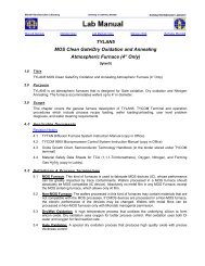
2.3 Run Schedules<br />
<strong>CMOS</strong>59 lot initiated and made it through step 23 (gate definition). At this point, because<br />
<strong>of</strong> staff changes, the lot was split into <strong>CMOS</strong>59a and <strong>CMOS</strong>59b for the rest <strong>of</strong> the steps,<br />
to optimize the new student and engineer’s learning curve. <strong>CMOS</strong>59a, <strong>CMOS</strong>59b and<br />
<strong>CMOS</strong>60 baseline lots were completed in the October 1999 and July 2000 time frame.<br />
<strong>Process</strong> timeline for these runs are shown in the Figure 3. <strong>CMOS</strong>59a process was delayed<br />
by equipment, the Al plasma etcher, which was down for about 3 weeks. <strong>CMOS</strong>60 run<br />
was delayed by 2 weeks due to a wafer stepper problem. However, the bottleneck usually<br />
is the implantation step, which takes about 1-2 weeks to complete by an outside service<br />
company.<br />
Step number<br />
50<br />
40<br />
30<br />
20<br />
10<br />
0<br />
25-Oct-99<br />
22-Nov-99<br />
20-Dec-99<br />
<strong>CMOS</strong>59a <strong>CMOS</strong>59b <strong>CMOS</strong>60<br />
17-Jan-00<br />
14-Feb-00<br />
13-Mar-00<br />
Date<br />
10-Apr-00<br />
8-May-00<br />
Figure 3. <strong>CMOS</strong> baseline schedule.<br />
8<br />
5-Jun-00<br />
3-Jul-00<br />
31-Jul-00
3. Test Results for <strong>CMOS</strong>58-<strong>CMOS</strong>60 Runs<br />
The results <strong>of</strong> SUPREM3, Spreading Resistance Analysis (SRA), HP4145<br />
Semiconductor Parameter Analyzer and the automatic probe testing are presented in this<br />
section.<br />
3.1 SUPREM3 Simulations and Spreading Resistance Analysis<br />
Spreading Resistance Analysis was requested for doping pr<strong>of</strong>iles <strong>of</strong> the N-channel, P-<br />
channel, N+ source-drain and P+ source-drain regions <strong>of</strong> the N and P-channel transistors.<br />
The SRA was performed by Solecon Laboratories (San Jose, CA). The results come from<br />
the lot <strong>CMOS</strong>59b. The scribe lane contains the appropriate structures for the<br />
measurements. Data can be seen in the <strong>Process</strong> and Device Parameters Table 3.<br />
N- and P-channel Area<br />
The simulated (SUPREM3) and measured doping pr<strong>of</strong>iles under the gate oxide for both<br />
types <strong>of</strong> transistors are shown in Figure 4. and 5. The simulated N-well junction depth is<br />
3.6 µm (Figure 4.a), while the SRA junction depth (Figure 5.a) is shallower, 3 µm. For<br />
P-well junction depth, the simulated (Figure 4.b) and measured (Figure 5.b) results are<br />
matched. The simulated surface concentration and the concentration close to the surface<br />
region show a cumulative effect <strong>of</strong> the threshold, punch through and the well<br />
implantations (Figure 4.a and 4.b). On the SRA graphs only the net concentration can be<br />
seen (Fig 5. and 7.).<br />
N+ and P+ Source-Drain<br />
The simulated source-drain doping pr<strong>of</strong>iles are in Fig. 6. The experimental results are in<br />
Fig. 7. The SRA junction depth in both cases (N+ source-drain and P+ source-drain) are<br />
shallower by 0.3 µm than the simulated value. The SRA junction depth is 0.4 µm for P+<br />
source-drain area and 0.12 µm for N+ source-drain area.<br />
9
(concentration) [#/cm3]<br />
1.E+17<br />
1.E+16<br />
1.E+15<br />
1.E+14<br />
1.E+13<br />
0 1 2 3 4 5 6<br />
depth [microns]<br />
Net<br />
Boron<br />
Phosphorus<br />
(concentration) [#/cm3]<br />
1E+17<br />
1E+16<br />
1E+15<br />
1E+14<br />
1E+13<br />
0 1 2 3 4 5 6<br />
depth [microns]<br />
(a) (b)<br />
Fig.4 Suprem-3 simulation results for areas under the gate oxide <strong>of</strong> <strong>CMOS</strong> transistors.<br />
(a) p-type transistor, (b) n-type transistor.<br />
(a) (b)<br />
Fig.5 Experimental results for areas under the gate oxide <strong>of</strong> <strong>CMOS</strong> transistors<br />
obtained from SRA. (a) p-type transistor, (b) n-type transistor.<br />
10<br />
Net<br />
Boron
(concentration) [#/cm3]<br />
1E+20<br />
1E+19<br />
1E+18<br />
1E+17<br />
1E+16<br />
1E+15<br />
1E+14<br />
1E+13<br />
0.0 0.2 0.4 0.6 0.8 1.0 1.2<br />
depth [microns]<br />
Net<br />
Boron<br />
Phosp<br />
horus<br />
(concentration) [#/cm3]<br />
1E+21<br />
1E+20<br />
1E+19<br />
1E+18<br />
1E+17<br />
1E+16<br />
1E+15<br />
1E+14<br />
1E+13<br />
0.0 0.2 0.4 0.6 0.8 1.0 1.2<br />
depth [microns]<br />
(a) (b)<br />
Fig 6 Suprem-3 simulation results for source-drain areas.<br />
(a) P+ source-drain, (b) N+ source-drain.<br />
(a) (b)<br />
Fig.7 Experimental results for source-drain areas obtained from SRA.<br />
(a) P+ source-drain, (b) N+ source-drain.<br />
11<br />
Net<br />
Boron<br />
Arsenic
3.2 HP4145B Measurement Results<br />
Manual measurements were taken using an HP4145 Semiconductor Parameter Analyzer,<br />
to display the I-V curves. NMOS and PMOS characteristics were obtained from<br />
<strong>CMOS</strong>59b process wafer#3. Although process was designed for 1.3 µm technology it can<br />
be seen that it works quite well for 1µm transistors (Figures 8 through 15). The features<br />
<strong>of</strong> the measured devices are W/L= 10/1 in Figures 8-15.<br />
Fig. 8. NMOS (W/L=10/1) drain current vs. drain voltage characteristics.<br />
Fig. 9 NMOS (W/L=10/1) drain current vs. gate voltage at varying substrate bias.<br />
12
Fig 10. NMOS (W/L=10/1) subthreshold characteristics.<br />
Fig 11. NMOS (W/L=10/1) drain current vs. gate voltage in saturation mode.<br />
Fig. 12. PMOS (W/L=10/1) drain current vs. drain voltage characteristics.<br />
13
Fig. 13 PMOS (W/L=10/1) drain current vs. gate voltage at varying substrate bias.<br />
Fig 14. PMOS (W/L=10/1) subthreshold characteristics.<br />
Fig 15. PMOS (W/L=10/1) drain current vs. gate voltage in saturation mode.<br />
14
3.3 Autoprober Measurement Results<br />
An automatic probe station (autoprober) was utilized to make electrical measurements on<br />
each lot. The autoprober consists <strong>of</strong> an Electroglas probe station Model 2001X, an HP<br />
4085A Switching Matrix, an HP4084 Switching Matrix Controller, an HP 4141<br />
Source/Monitor (later HP 4142) and a UNIX workstation. The test structures are laid out<br />
such that the contact pads allowed for a 2x5 probe-card testing.<br />
The autoprober enables the collection <strong>of</strong> large amounts <strong>of</strong> data for monitoring the process<br />
and for extracting device parameters. The source files for the SUNBASE control s<strong>of</strong>tware<br />
can be found in: ~eglas/src/sunbase/ on the <strong>Microlab</strong>’s main file server (silicon) and also<br />
are listed in Appendix B. The program extracts the threshold voltage, effective channel<br />
length/width, body factor, surface dopant concentration, drain induced barrier lowering,<br />
with the right setting <strong>of</strong> the prober.text and die.map files. Eighteen dies were tested on<br />
each wafer for threshold voltage. These measured dies were uniformly distributed across<br />
the wafer. Figures 16 and 17 show threshold voltage distributions <strong>of</strong> lots <strong>CMOS</strong>58-60.<br />
15
0.035<br />
0.03<br />
0.025<br />
0.02<br />
0.015<br />
0.01<br />
0.005<br />
0<br />
cmos58<br />
cmos59a<br />
(a) (b)<br />
Vtn S.D. [V]<br />
cmos59b<br />
Fig. 16. (a) NMOS threshold voltage distribution, (b) standard deviation corresponding to data points in (a).<br />
Vtp [V]<br />
Vtn [V]<br />
1.2<br />
1.1<br />
1<br />
0.9<br />
0.8<br />
0.7<br />
0.6<br />
0.5<br />
0.85<br />
0.8<br />
0.75<br />
0.7<br />
0.65<br />
0.6<br />
0.55<br />
0.5<br />
cmos58<br />
cmos58<br />
cmos59a<br />
cmos59a<br />
cmos59b<br />
cmos59b<br />
cmos60<br />
cmos60<br />
y = 0.7328<br />
y = 0.8741<br />
Vtp S.D. [V]<br />
0.04<br />
0.035<br />
0.03<br />
0.025<br />
0.02<br />
0.015<br />
0.01<br />
0.005<br />
0<br />
cmos58<br />
cmos59a<br />
cmos59b<br />
(a) (b)<br />
Fig.17. PMOS threshold voltage distribution, (b) standard deviation corresponding to data points in (a).<br />
16
3.4 Design Parameters<br />
Table 3. below is the summary <strong>of</strong> the various measurements and testing results from the<br />
process designed to produce L=1.3 µm devices. However, also L=1 µm devices also<br />
worked well. Numbers shown were extracted from measurements on L=1 µm devices.<br />
Table 3. <strong>Process</strong> and Device Parameters Targets (from 10/1 device)<br />
No. Parameters Units NMOS PMOS<br />
1. Vthreshold V 0.7 0.8<br />
2. Subthreshold Slope mV/decade 99 125<br />
3. K’(µCox/2) µA/V 2 18 9<br />
4. dL µm 0.051 0.047<br />
5. dW µm 0.522 0.54<br />
6. γ1 (low VSB) V 1/2 0.795 -0.446<br />
7. γ2 (high VSB) V 1/2 0.591 -0.371<br />
8. Surface dopant concentration Atom/cm 3 5.68E16 1.79E16<br />
9. Substrate dopant concentration Atom/cm 3 3.14E16 1.25E16<br />
10. Tox Angstrom 200 +/-20 200 +/-20<br />
11. Xj (S-D) µm 0.14 0.4<br />
12. Xw (Well depth) µm 4.7 3<br />
13. Rdiff (sheet resistance) Ω/square 190 171<br />
14. Rpoly (sheet resistance) Ω/square 33 33<br />
15. Rwell (sheet resistance) KΩ/square 0.5 1.5<br />
16. Rc M1-diff (2µmx2µm) Ω 46 47<br />
17. Rc M1-poly (2µmx2µm) Ω 8.8 8.8<br />
18. ⏐Vth-field⏐ V 10 10<br />
19. ⏐S-D Breakdown⏐ V >7 >10<br />
17
3.5 Method and measurement conditions<br />
1. The threshold voltage was measured by the linear extrapolation method. The program<br />
used is attached in Appendix B.<br />
2. Subthreshold slope numbers come HP 4145 measurements.<br />
3. K’ were extracted from measurements while the devices were at saturation (HP 4145B<br />
Semiconductor Parameter Analyzer).<br />
4-5. Effective channel length and width were measured by autoprober, based on the<br />
resistance and conductance methods [7].<br />
6-7. Gamma1, gamma2 were calculated by the autoprober program. The source files are<br />
in Appendix B.<br />
8-9. Surface dopant concentration numbers come from autoprober measurements, which<br />
matched with SRA results. Since the dopant concentration is not vertically uniform in the<br />
ion-implanted channel region, gamma1 and gamma2 were extracted at low and high<br />
substrate bias [8]. Based on these results, dopant concentrations at the surface and<br />
substrate were obtained.<br />
10. Gate oxide thickness was measured by Nanospec during the process.<br />
11-12. The well depth and the source-drain depth data arise from the SRA graphs.<br />
13-17. Parameters were measured on the automatic probe station using the electrical test<br />
structures described in Ref [5].<br />
18-19. Measurements taken by the Semiconductor Parameter Analyzer.<br />
4. Future work<br />
We are in the process <strong>of</strong> implementing a deep UV lithography stepper (PAS 5500/90,<br />
ASML donation). This new stepper can resolve minimum feature sizes down to 0.3 µm.<br />
The new and more advance lithography in conjunction with other process modules such<br />
as: lightly doped drain (LDD), retrograde well and possibly salicide will enable to us<br />
develop new technology for the <strong>Microlab</strong>’s baseline process. The baseline <strong>CMOS</strong> will be<br />
the test vehicle for qualifying the 6” process line upgrade in the <strong>Microlab</strong>.<br />
18
5. References<br />
[1] Katalin Voros and Ping K. Ko, MOS <strong>Process</strong>es in the Micr<strong>of</strong>abrication Laboratory,<br />
Memorandum No. UCB/ERL M87/12, Electronics Research Laboratory, <strong>University</strong> <strong>of</strong><br />
California, <strong>Berkeley</strong> (10 March 1987)<br />
[2] Katalin Voros and Ping K.Ko, Evolution <strong>of</strong> the Micr<strong>of</strong>abrication Facility at <strong>Berkeley</strong>,<br />
Memorandum No. UCB/ERL M89/109, Electronics Research Laboratory, <strong>University</strong> <strong>of</strong><br />
California, <strong>Berkeley</strong> (22 September 1989)<br />
[3] Andrea E. Franke, Polycrystalline Silicon-Germanium Films for Integrated<br />
Microsystems, PhD dissertation, Department <strong>of</strong> Electrical Engineering and Computer<br />
Sciences, <strong>University</strong> <strong>of</strong> California, <strong>Berkeley</strong>, (December 2000)<br />
[4] Paul M. Krueger, Tuning a Statistical <strong>Process</strong> Simulator to a <strong>Berkeley</strong> <strong>CMOS</strong><br />
<strong>Process</strong>, Memorandum No. UCB/ERL M88/82, Electronics Research Laboratory,<br />
<strong>University</strong> <strong>of</strong> California (15 December 1988)<br />
[5] David Rodriguez, Electrical Testing <strong>of</strong> a <strong>CMOS</strong> <strong>Baseline</strong> <strong>Process</strong>, Memorandum No.<br />
UCB/ERL M94/63, Electronics Research Laboratory, <strong>University</strong> <strong>of</strong> California, <strong>Berkeley</strong><br />
(30 August 1994)<br />
[6] Shenqing Fang, <strong>CMOS</strong> <strong>Baseline</strong> process in the UC <strong>Berkeley</strong> Micr<strong>of</strong>abrication<br />
Laboratory, Memorandum No. UCB/ERL M95/98, Electronics Research Laboratory,<br />
<strong>University</strong> <strong>of</strong> California, <strong>Berkeley</strong> (20 December 1995)<br />
[7] D.K. Schroder, Semiconductor Material and Device Characterization, New York:<br />
John Wiley & Sons, Inc., 1990.<br />
[8] Chenming Hu and Yuhua Cheng, MOSFET modeling & BSIM3 User’s Guide,<br />
Kluwer Academic Publishers, pp. 80-81, 1999<br />
19
Acknowledgments<br />
The author is grateful to Katalin Voros <strong>Microlab</strong> Operations Manager and Sia Parsa<br />
<strong>Process</strong> Engineering Manager for their encouragement and valuable support. The<br />
baseline project acknowledges support from Pr<strong>of</strong>essors Gray, Spanos and BSAC<br />
directors.<br />
Biography<br />
Laszlo Voros received his Master <strong>of</strong> Science degree in engineering physics in 1999 from<br />
the Technical <strong>University</strong> <strong>of</strong> Budapest, in Hungary. He spent 1999 and 2000 at UCB as an<br />
associate specialist in the Micr<strong>of</strong>abrication Laboratory. His primary assignments were in<br />
baseline process support and development, device testing.<br />
20
Appendix A<br />
<strong>Microlab</strong> <strong>CMOS</strong> <strong>Process</strong><br />
Version 5.0 (Nov. 1997)<br />
1.3 um, twin-well, double poly-Si, double metal<br />
________________________________________________________________________<br />
0.0 Starting Wafers: 24-36 ohm-cm, p-type, <br />
Control wafers: PCH, NCH.<br />
Scribe lot and wafer number on each wafer, including controls.<br />
Piranha clean and dip in sink8.<br />
Measure bulk resistivity (ohms-cm) <strong>of</strong> each on sonogage.<br />
R =<br />
________________________________________________________________________<br />
1.0 Initial Oxidation: target = 30 (+/- 5%) nm<br />
________________________________________________________________________<br />
1.1 TCA clean furnace tube (tylan5), reserve tylan9.<br />
_______________________________________________________________________<br />
1.2 Standard clean wafers in sink6:<br />
Include PCH and NCH.<br />
piranha 10 minutes, 10/1 HF dip, spin-dry.<br />
________________________________________________________________________<br />
1.3 Dry oxidation at 950 C (SGATEOX):<br />
60 min. dry O2 (Check the previous run result)<br />
20 min. dry N2<br />
Ox. time=<br />
measure oxide thickness on PCH, Tox=<br />
________________________________________________________________________<br />
2.0 Nitride Deposition (SNITC):<br />
Transfer wafers to tylan9 right after 1.3 and deposit<br />
Only include NCH.<br />
100 nm nitride. Dep. time=<br />
measure nitride thickness on NCH, Tnit=<br />
________________________________________________________________________<br />
3.0 Well Photo: Mask NWELL (CWN chrome-df)<br />
(Control wafers are not included in any photoresist step)<br />
Standard I-line process:<br />
HMDS, spin (and s<strong>of</strong>t bake), expose, post exposure bake,<br />
develop, inspect, descum and hard bake.<br />
________________________________________________________________________<br />
4.0 Etch: Plasma etch nitride in lam1.<br />
Recipe: Power:<br />
Actual Etch Time: Overetch:<br />
Check the oxide thickness on each work wafer:<br />
________________________________________________________________________<br />
5.0 N-Well Implant: phosphorus, 4E12/cm2, 80 KeV. Include PCH.<br />
________________________________________________________________________<br />
6.0 N-Well Cover Oxidation:<br />
________________________________________________________________________<br />
6.1 TCA clean furnace tube (tylan2).<br />
1
________________________________________________________________________<br />
6.2 Remove PR in O2 plasma and clean wafers in sink8.<br />
________________________________________________________________________<br />
6.3 Standard clean wafers in sink6, include PCH and NCH.<br />
________________________________________________________________________<br />
6.4 Well cover oxidation at 950 (NWELLCVR):<br />
30 min. dry O2<br />
175 min. wet O2<br />
30 min. dry O2<br />
20 min. N2<br />
________________________________________________________________________<br />
7.0 Nitride Removal, include NCH<br />
________________________________________________________________________<br />
7.1 Dip in 10:1 BHF for 40 sec to remove thin oxide on top <strong>of</strong> Si3N4.<br />
________________________________________________________________________<br />
7.2 Etch nitride <strong>of</strong>f in boiling phosphoric acid (sink7).<br />
Measure Tox in n-well on work wafers.<br />
________________________________________________________________________<br />
8.0 P-Well Implant: B11, 3E12/cm2, 80 KeV. Include NCH<br />
________________________________________________________________________<br />
9.0 Well Drive-In:<br />
________________________________________________________________________<br />
9.1 TCA clean furnace tube (tylan2).<br />
________________________________________________________________________<br />
9.2 Standard clean wafers in sink8 and 6. Include PCH and NCH.<br />
________________________________________________________________________<br />
9.3 Well drive at 1120 C (WELLDR):<br />
60 min. temperature ramp from 750 C to 1120 C<br />
240 min. dry O2<br />
300 min. N2<br />
Measure oxide thickness on two control wafers.<br />
tox (PCH)= tox (NCH) =<br />
________________________________________________________________________<br />
9.4 Strip oxide in 5:1 BHF.<br />
Measure Rs on PCH and NCH.<br />
Rs (PCH) = Rs(NCH) =<br />
________________________________________________________________________<br />
10.0 Pad Oxidation/Nitride Deposition:<br />
target = 30 (+6) nm SiO2 + 100 (+10) nm Si3N4<br />
________________________________________________________________________<br />
10.1 TCA clean furnace tube (tylan5). Reserve tylan9.<br />
________________________________________________________________________<br />
10.2 Standard clean wafers. Include PCH, NCH.<br />
________________________________________________________________________<br />
2
10.3 Dry oxidation at 950 C (SGATEOX):<br />
~1 hr. dry O2<br />
30 minutes dry N2 anneal.<br />
Measure the oxide thickness on NCH<br />
Tox=<br />
________________________________________________________________________<br />
10.4 Deposit 100 (+10) nm <strong>of</strong> Si3N4 immediately (SNITC):<br />
Only include PCH.<br />
approx.time = 22 min., temp.= 800 C.<br />
Measure nitride thickness on PCH.<br />
Tnit =<br />
________________________________________________________________________<br />
11.0 Active Area Photo: Mask ACTV (ACTV emulsion-cf)<br />
Standard I-line process.<br />
________________________________________________________________________<br />
12.0 Nitride Etch:<br />
Plasma etch nitride in lam1. Recipe:<br />
Power: Time: Overetch:<br />
Measure Tox on each work wafer. (2 pnts measurement).<br />
Do not remove PR. Inspect.<br />
Measure PR thickness covering active area. tpr=<br />
PR must be >800 nm. Hard bake again for >2hrs at 120 C.<br />
________________________________________________________________________<br />
13.0 P-Well Field Implant Photo: Mask PFIELD (CWNI emulsion-cf)<br />
(Reversed NWELL mask)<br />
Standard I-line process. (Second photo)<br />
N-Well area is covered with PR.<br />
________________________________________________________________________<br />
14.0 P-Well Field Ion Implant: B11, 70 KeV, 1.5E13/cm2.<br />
________________________________________________________________________<br />
15.0 N-Well Field Implant Photo: Mask NWELL (CWN chrome-df)<br />
________________________________________________________________________<br />
15.1 Remove PR in plasma O2. Clean wafers in sink8.<br />
________________________________________________________________________<br />
15.2 Standard I-line process.<br />
________________________________________________________________________<br />
16.0 N-Well Field Ion Implant: phosphorus, 40 KeV, 3E12.<br />
________________________________________________________________________<br />
17.0 Locos Oxidation: target = 650 nm<br />
________________________________________________________________________<br />
17.1 TCA clean furnace tube (tylan2).<br />
________________________________________________________________________<br />
17.2 Remove PR in O2 plasma and piranha clean wafers.<br />
Standard clean wafers; dip in BHF 25:1 for 5-10 sec.<br />
Include PCH, NCH.<br />
________________________________________________________________________<br />
3
17.3 Wet oxidation at 950 C (SWETOXB):<br />
5 min. dry O2<br />
4 hrs. 40 min. wet O2<br />
5 min. dry O2<br />
20 min. N2 anneal<br />
Measured tox on 3 work wafers. Tox=<br />
________________________________________________________________________<br />
18.0 Nitride Removal, include PCH.<br />
________________________________________________________________________<br />
18.1 Dip in 10:1 BHF for 60 sec to remove thin oxide on top <strong>of</strong> Si3N4.<br />
________________________________________________________________________<br />
18.2 Etch nitride <strong>of</strong>f in phosphoric acid at 145 C (sink7).<br />
________________________________________________________________________<br />
19.0 Sacrificial Oxide: target = 20 (+/- 2) nm<br />
________________________________________________________________________<br />
19.1 TCA clean furnace tube (tylan5).<br />
________________________________________________________________________<br />
19.2 Standard clean wafers, include NCH and PCH.<br />
Dip in 10:1 BHF until PCH and NCH dewet.<br />
________________________________________________________________________<br />
19.3 Dry oxidation at 950 C (SGATEOX):<br />
30 minutes dry O2<br />
30 minutes N2 anneal<br />
Measure Tox on PCH and NCH. Tox=<br />
________________________________________________________________________<br />
20.0 N-Channel Punchthrough and Threshold Adjustment Photo: Mask PFIELD<br />
(CWNI emulsion-cf).<br />
Standard I-line process.<br />
________________________________________________________________________<br />
21.0 N-Channel Punchthrough and Threshold Adjustment Implant. Include NCH.<br />
1) B11, 120 KeV, 8E11/cm2.<br />
2) B11, 30 KeV, 1.9E12/cm2.<br />
________________________________________________________________________<br />
22.0 P-Channel Punchthrough and Threshold Adjustment Photo: Mask PVT<br />
(PVT chrome-df).<br />
Remove PR in plasma O2 and clean wafers in sink8.<br />
Standard I-line process.<br />
________________________________________________________________________<br />
23.0 P-Channel Punchthrough and Threshold Adjustment Implant. Include PCH.<br />
1) Phosphorus, 190 KeV, 1E12,<br />
2) B11, 20 KeV, 2.4E12.<br />
________________________________________________________________________<br />
24.0 Gate Oxidation/Poly-Si Deposition:<br />
target = 20 (+/- 2.0) nm SiO2 + 450 (+/- 40) nm poly-Si<br />
________________________________________________________________________<br />
4
24.1 TCA clean furnace tube (tylan5).<br />
Reserve poly-Si deposition tube (tylan11).<br />
________________________________________________________________________<br />
24.2 Standard clean wafers, include PCH, NCH,<br />
Tox (prime P), and one Tpoly1 monitoring wafers.<br />
________________________________________________________________________<br />
24.3 Dip <strong>of</strong>f sacrificial oxide in 10:1 HF<br />
until NCH and PCH dewet (approx. 1 min).<br />
________________________________________________________________________<br />
24.4 Dry oxidation at 950 C (SGATEOX):<br />
30 min dry O2 (Check previous run result)<br />
30 min N2 anneal.<br />
________________________________________________________________________<br />
24.5 Immediately after oxidation deposit 450 nm <strong>of</strong> phos.doped<br />
poly-Si (SDOPOLYI).<br />
only include Tpoly1.<br />
approx.time = 2 hr. 20 min., temp.= 610 C<br />
(Check previous run result)<br />
________________________________________________________________________<br />
24.6 Measurements<br />
a) Measure oxide thickness on Tox, PCH and NCH.<br />
b) Measure Dit and Qox on Tox.<br />
c) Strip oxide from PCH and NCH, and measure the sheet<br />
resistivity.<br />
d) Measure poly thickness on Tpoly1.<br />
PCH and NCH proceed to step 27.2.<br />
Tpoly1 proceeds to step 32.3.<br />
________________________________________________________________________<br />
25.0 Gate Definition: Mask POLY (emulsion-cf)<br />
Standard I-Line process.<br />
________________________________________________________________________<br />
26.0 Plasma etch poly-Si<br />
________________________________________________________________________<br />
26.1 Etch poly in Lam4 (Recipe: 400):<br />
Pwr: Ave. etch time: Overetch:<br />
________________________________________________________________________<br />
26.2 Measure Tox in S/D area <strong>of</strong> each work wafer (2 pnts measurement).<br />
________________________________________________________________________<br />
26.3 Measure channel length using 1.0um gate.<br />
CD =<br />
________________________________________________________________________<br />
27.0 Reoxidation and Capacitor Formation:<br />
(If no capacitor is requested, skip step 27 through 29.2.)<br />
________________________________________________________________________<br />
27.1 TCA clean furnace tube (tylan2). Reserve tylan12 and tylan11.<br />
________________________________________________________________________<br />
27.2 Standard clean wafers, including PCH, NCH, and<br />
5
two monitoring wafers, one for dry oxidation (Tpoly2) and<br />
one for LTO.<br />
From here on: only 10 sec dip in 25/1 H2O/HF after piranha.<br />
________________________________________________________________________<br />
27.3 Dry oxidation at 900 C (SDRYOXB):<br />
30 min dry O2<br />
20 min N2 anneal.<br />
Measure oxide thickness on Tpoly2:<br />
Tpoly2 proceeds to Step 27.5.<br />
PCH proceeds to Step 34 and NCH proceeds to Step 31.<br />
________________________________________________________________________<br />
27.4 1) Run a coating and monitoring LTO in tylan12 to get<br />
dep rate. Use recipe VDOLTOC and set 0 doping.<br />
2) Deposit LTO for the desired oxide thickness.<br />
3) Measure LTO thickness on monitoring wafer:<br />
________________________________________________________________________<br />
27.5 Second poly-Si deposition: immediately after oxidation<br />
deposit 450 nm <strong>of</strong> phos.doped poly-Si (SDOPOLYH):<br />
only include Tpoly2.<br />
approx.time = 2 hr. 18 min, temp.= 610 C.<br />
Measure second poly thickness on Tpoly2:<br />
Tpoly2 proceeds to step 32.3.<br />
________________________________________________________________________<br />
28.0 Capacitor Photo: Mask CAP-CE (CAP emulsion-cf)<br />
Standard I-Line process.<br />
________________________________________________________________________<br />
29.0 Plasma etch poly-Si:<br />
________________________________________________________________________<br />
29.1 Etch 2nd poly in Lam4 (Recipe: 400):<br />
Power: Actual etch time: Overetch:<br />
________________________________________________________________________<br />
29.2 Measure Tox in S/D area on each work wafer.<br />
Remove PR in O2 plasma.<br />
Piranha clean wfrs in sink8.<br />
Dehydrate wfrs in oven for > 30 min. at 120 C.<br />
________________________________________________________________________<br />
30.0 N+ S/D Photo: Mask N+S/D (NSD chrome-df)<br />
Standard I-line process.<br />
________________________________________________________________________<br />
31.0 N+ S/D Implant: Arsenic, 100 keV, 5E15/cm2, include NCH.<br />
________________________________________________________________________<br />
32.0 N+ S/D Anneal<br />
________________________________________________________________________<br />
32.1 TCA clean furnace tube (tylan7).<br />
________________________________________________________________________<br />
32.2 Remove PR in O2 plasma and piranha clean wafers<br />
in sink8 (no dip here).<br />
________________________________________________________________________<br />
6
32.3 Standard clean wafers in sink6, incl. PCH, NCH, Tpoly1,<br />
and Tpoly2.<br />
________________________________________________________________________<br />
32.4 Anneal in N2 at 900 C for 30 min (N2ANNEAL).<br />
________________________________________________________________________<br />
32.5 Strip oxide from NCH, Tpoly1, and Tpoly2.<br />
Measure Rs <strong>of</strong> N+ S/D implant: Rs(NCH)=<br />
Measure Rs <strong>of</strong> poly1 on Tpoly1: Rs(Tpoly1)=<br />
Measure Rs <strong>of</strong> poly2 on Tpoly2: Rs(Tpoly2)=<br />
________________________________________________________________________<br />
33.0 P+ S/D Photo: Mask P+S/D (PSD emulsion-cf)<br />
Standard I-line process.<br />
________________________________________________________________________<br />
34.0 P+ S/D Implant: B11, 20 keV, 5E15/cm2, include PCH.<br />
________________________________________________________________________<br />
35.0 PSG Deposition and Densification: target = 700 nm<br />
________________________________________________________________________<br />
35.1 Remove PR in O2 plasma and clean wafers in sink8 (no dip).<br />
________________________________________________________________________<br />
35.2 Standard clean wafers in sink6 (10 sec dip).<br />
Include one PSG monitoring wafer.<br />
________________________________________________________________________<br />
35.3 Deposit 700 nm PSG, PH3 flow at 10.3 sccm (SDOLTOD).<br />
approx.time = 22 min. (check current dep. rate)<br />
temp. = 450 C<br />
________________________________________________________________________<br />
35.4 Densify glass in tylan2 at 900 C, immediately after<br />
PSG deposition (PSGDENS). Include PSG control.<br />
5 min dry O2<br />
20 min wet O2<br />
5 min dry O2<br />
Measure tPSG (using PSG control and working wafers):<br />
N+ region Tox =<br />
P+ region Tox =<br />
Etch oxide on PCH.<br />
Measure Rs <strong>of</strong> P+ S/D implant: Rs(PCH)=<br />
________________________________________________________________________<br />
35.5 Do wet oxidation dummy run afterwards to clean tube:<br />
1 hr wet oxidation at 950 C (SWETOXB).<br />
________________________________________________________________________<br />
36.0 Contact Photo: Mask CONT (CONT chrome-df)<br />
Standard I-Line process.<br />
________________________________________________________________________<br />
37.0 Contact Plasma Etch in lam2:<br />
Recipe: Power: Etch time: Overetch:<br />
________________________________________________________________________<br />
7
38.0 Back side etch:<br />
________________________________________________________________________<br />
38.1 Remove PR in O2 plasma, piranha clean wafers in sink8 (no dip).<br />
Dehydrate wafers in oven at 120 C for >30 min.<br />
________________________________________________________________________<br />
38.2 Etch backside:<br />
(PCH and NCH can be included in b), c) and d).<br />
a) Spin PR on front side, hard bake.<br />
b) Dip <strong>of</strong>f oxide (PSG) in 5:1 BHF.<br />
c) Etch poly-Si (poly2 thickness) in lam4.<br />
d) Etch oxide <strong>of</strong>f in 5:1 BHF (cap. ox. thickness).<br />
e) Etch poly-Si (poly1 thickness) in lam1.<br />
f) Final dip in BHF until back dewets.<br />
g) Remove PR in PRS2000, piranha clean wfrs in sink8<br />
(no dip).<br />
________________________________________________________________________<br />
39.0 Metallization: target = 600 nm<br />
Stnd clean wfrs and do a 30 sec. 25/1 H2O/HF dip just<br />
before metallization.<br />
Sputter Al/2% Si on all wafers in CPA.<br />
________________________________________________________________________<br />
40.0 Metal Photo: Mask METAL1-CM (M1 emulsion-cf)<br />
Standard I-line process.<br />
________________________________________________________________________<br />
41.0 Plasma etch Al in Lam3.<br />
Remove PR in PRS2000 or technics-c. tAl=<br />
Probe test devices.<br />
________________________________________________________________________<br />
42.0 Sintering: 400 C for 20min in forming gas (tylan13).<br />
No ramping, use SINT400 program.<br />
________________________________________________________________________<br />
43.0 Testing:<br />
1.0 um N- and P-channel devices, capacitors and inverter<br />
Measure the sheet resistivities <strong>of</strong> PCH and<br />
NCH on prometrix.<br />
________________________________________________________________________<br />
44.0 Planerization and Dielectric Film Deposition:<br />
________________________________________________________________________<br />
44.1 PECVD thin oxide (50 nm) in technics-B:<br />
N2O: 54.0, Silane: 14.0, Pwr: 15 W, Pressure: 360-420 mT.<br />
~5 min. Measure Tox on dummy wafers.<br />
________________________________________________________________________<br />
44.2 SOG coating on the Headway spinner at 3000 rpm.<br />
________________________________________________________________________<br />
44.3 SOG cure:<br />
a) Oven in Y2, 120 C, 30 min.<br />
b) Oven in R1, 200 C, 30 min.<br />
c) Tylan14 (SVANNEAL): 400oC, 30 min.<br />
8
d) Measure Tox and refractive index on dummy wafers.<br />
________________________________________________________________________<br />
44.4 ECR thick oxide (900 nm) in pqecr:<br />
Check the deposition rate <strong>of</strong> previous run.<br />
Measure Tox and refractive index on dummy wafers.<br />
________________________________________________________________________<br />
45.0 VIA Photo: Mask VIA (VIA chrome-df)<br />
Standard I-line process.<br />
________________________________________________________________________<br />
46.0 Etch VIA in lam2.<br />
Recipe: Etch time: Overetch:<br />
Need overetch.<br />
________________________________________________________________________<br />
47.0 Metal2 Metallization. target = 800-900 nm<br />
Remove PR in PRS2000 or technics-c. Rinse the wafers in<br />
sink7 and spin dry.<br />
Sputter Al/2% Si CPA.<br />
________________________________________________________________________<br />
48.0 Metal Photo: Mask METAL2-CM (M2 emulsion-cf)<br />
Standard I-line process.<br />
Hard bake for >2 hrs.<br />
________________________________________________________________________<br />
49.0 Plasma etch Al in Lam3.<br />
Remove PR in PRS2000.<br />
________________________________________________________________________<br />
50.0 Sintering: 400 C for 20min in forming gas (tylan13).<br />
No ramping, use SINT400 program.<br />
________________________________________________________________________<br />
51.0 Testing:<br />
Measure Metal1 and Metal2 contact chain.<br />
________________________________________________________________________<br />
End <strong>of</strong> <strong>Process</strong><br />
________________________________________________________________________<br />
Appendix: <strong>CMOS</strong>43 Aligment Offsets, GCA 6200 Wafer Stepper<br />
box,center,expand;<br />
c c c c<br />
c c c c<br />
c c c c<br />
c c c c<br />
c c c c<br />
c c c c<br />
c c c c<br />
c c c c<br />
XSHIFT YSHIFT Label on Mark<br />
CWN (nwell) 0 -3.250 PCH CWN<br />
CAA (active) .200 -3.250 ACTIVE CAA<br />
CPG (poly gate) .400 -3.250 GATE CPG<br />
CCA (contact) .600 -3.250 CONTACT CCA<br />
9
M1 (metal1) .800 -3.250 METAL1 CMF<br />
VIA 1.20 -3.250 CONTACT CVA<br />
M2 (metal2) 1.00 -3.250 METAL2 CM2<br />
10
#define MODULE "VTWDLD"<br />
#include "modtools.h"<br />
#include "vt.h"<br />
#include "ld.h"<br />
#include "wd.h"<br />
#include "dibl.h"<br />
module_function VTWDLD;<br />
Appendix B<br />
AUTOPROBER PROGRAM<br />
(SUNBASE)<br />
typedef struct {<br />
float VGSstart;<br />
float VGSstop;<br />
float VGSstep;<br />
float VBSstart;<br />
float VBSstop;<br />
float VBSstep;<br />
float VDS;<br />
float NoiseLevel;<br />
int RegPoints;<br />
int MaxTries;<br />
float SlopeTol;<br />
float tox; /*in A, 1e-10m, or 1e-8 cm, need to<br />
convert to cm when using*/<br />
float Npeak;<br />
} BODYE_param;<br />
/*VDS changed to 25mV now, 50mV originally*/<br />
#define BODYE_N_PAR {\<br />
/* VGSstart */ 0.0,\<br />
/* VGSstop */ 6.0,\<br />
/* VGSstep */ 0.1,\<br />
/* VBSstart */ 0,\<br />
/* VBSstop */ -5,\<br />
/* VBSstep */ -.2,\<br />
/* VDS */ 25e-3,\<br />
/* NoiseLevel */1e-8,\<br />
/* RegPoints */ 5,\<br />
/* MaxTries */ 5,\<br />
/* SlopeTol */ 0.4,\<br />
/* tox(A) */ 300.0,\<br />
/* Npeak */ 4.5e16\<br />
};<br />
/*VDS changed to 25mV now, 50mV originally*/<br />
#define BODYE_P_PAR {\<br />
/* VGSstart */ 0.0,\<br />
/* VGSstop */ -6.0,\<br />
/* VGSstep */ -0.1,\<br />
/* VBSstart */ 0,\<br />
/* VBSstop */ 5,\<br />
/* VBSstep */ .2,\<br />
/* VDS */ -25e-3,\<br />
/* NoiseLevel */ 1e-8,\<br />
/* RegPoints */ 5,\<br />
/* MaxTries */ 5,\<br />
/* SlopeTol */ 0.4,\<br />
/* tox(A) */ 300.0,\<br />
/* Npeak */ 3.5e16\<br />
};
#include "vtldwd.h"<br />
#include "cf.h"<br />
extern VT_param VT_N_par;<br />
extern VT_param VT_P_par;<br />
extern LD_param LD_N_par;<br />
extern LD_param LD_P_par;<br />
extern WD_param WD_N_par;<br />
extern WD_param WD_P_par;<br />
extern DIBL_param DIBL_N_par;<br />
extern DIBL_param DIBL_P_par;<br />
extern BODYE_param BODYE_N_par;<br />
extern BODYE_param BODYE_P_par;<br />
BODYE_param BODYE_N_par = BODYE_N_PAR;<br />
BODYE_param BODYE_P_par = BODYE_P_PAR;<br />
typedef struct {<br />
char text[20];<br />
int ld, vt, dibl, wd, bodye;<br />
int Y;<br />
float vt_VBS[30];<br />
float vt_sum[30];<br />
float vt_sum2[30];<br />
int vt_count[30];<br />
float Gamma_sum;<br />
float Gamma_sum2;<br />
int Gamma_count;<br />
float Gamma1_sum;<br />
float Gamma1_sum2;<br />
int Gamma1_count;<br />
float Gamma2_sum;<br />
float Gamma2_sum2;<br />
int Gamma2_count;<br />
float N_sur_sum;<br />
float N_sur_sum2;<br />
int N_sur_count;<br />
float N_sub_sum;<br />
float N_sub_sum2;<br />
int N_sub_count;<br />
int cferror[8];<br />
} TrnType;<br />
static void BODYE_regression(double datarray[30][2], int index1,<br />
int index2, double *a,double *b);<br />
static void BODYE_readparams(BODYE_param *P, char ***paramptr);<br />
static void measres(char type, FetType *dut, LD_param *P, FILE *flderr,<br />
float data[MNOTRN][1+MNOLINES],<br />
char baddev[MNOTRN][20], int *trn, int *errors, int *numpoints);<br />
static double measvt(VT_param *P, char type, FetType *dut,<br />
FILE *fvt, FILE *fvterr,<br />
TrnType **trnlist, int *vt_VBS_ct);<br />
static void measbodye(BODYE_param *P, VT_param *vtP, char type, FetType *dut,<br />
FILE *fbodye, TrnType **trnlist);<br />
static void make_list(char **paramlist, TrnType ***trnlstptr,int *bvt,<br />
int *bld, int *bwd, int *bdibl, int *bbodye,<br />
VT_param **vtP, WD_param **wdP, LD_param **ldP,<br />
DIBL_param **diblP,BODYE_param **bodyeP, char *type, int *wdCount,<br />
int *diblCount);<br />
static void statsLd (TrnType **trnlist, float ld_sum[3], float ld_sum2[3],<br />
int ld_count[3], int ld, int vt_VBS_ct);<br />
static void statsVt (TrnType **trnlist, int vt_VBS_ct);<br />
static void statsGamma (TrnType **trnlist);<br />
/*Given resistance vs length, calculate delta lengths*/<br />
static void ldCal(TrnType **trnlst, int w5, int w10, int w50,<br />
float data[3][MNOTRN][1+MNOLINES],<br />
int trn[3], int errors[3], char baddev[3][MNOTRN][20],
{<br />
}<br />
int numpoints, int ld, int last, int vt_VBS_ct)<br />
float w;<br />
float a[MNOLINES], b[MNOLINES], x[MNOPTS], r[MNOPTS], res, dl;<br />
int wi, i, j, k,m;<br />
static float ld_sum[3]={0,0,0}, ld_sum2[3]={0,0,0};<br />
static int FirstTime=1, ld_count[3]={0,0,0};<br />
static FILE* fld;<br />
typedef enum {GOOD, BAD} StatusType;<br />
StatusType deviceStatus=GOOD;<br />
if (FirstTime) {<br />
fld=fopen("out.ld", "w");<br />
fprintf(fld, "dieX\tdieY\twidth\tLd\tRes\tTransistors Discarded\n");<br />
FirstTime=0;<br />
}<br />
for (wi=0;wi1) {<br />
LD_regression(data[wi], trn[wi], numpoints, a, b);<br />
k=0;<br />
for (i=0; i
*function to call different combined routines: threshold<br />
*voltage(vt), delta width(wd), delta length(ld), body<br />
*effect(bodye), drain-induced barrier lowering(dibl) and<br />
*its dibl's relating parameters such as subthreshold swing,<br />
*Source-Drain leakage, depending on the specification in<br />
*prober.text.*/<br />
void *VTWDLD (char **paramlist, FILE *dummy, int last)<br />
{<br />
float data[3][MNOTRN][1+MNOLINES];<br />
static int FirstTime=1, vt_VBS_ct;<br />
static VT_param *vtP;<br />
static LD_param *ldP;<br />
static WD_param *wdP;<br />
static DIBL_param *diblP;<br />
static BODYE_param *bodyeP;<br />
static char type;<br />
static int wdCount=0;<br />
static int diblCount=0;<br />
char baddev[3][MNOTRN][20];<br />
int numpoints, wi, cferr, w5, w10, w50,<br />
trn[3]={0,0,0}, errors[3]={0,0,0};<br />
double i;<br />
static int vt, wd, ld, dibl, bodye, inv;<br />
static TrnType **trnlst;<br />
TrnType **trnlist;<br />
FetType *dut;<br />
static FILE *fcf, *fvt, *fvterr, *flderr, *fbodye;<br />
double vtUse, bigVDS;<br />
D(printf ("> VTWDLD\n"););<br />
if (FirstTime) {<br />
make_list(paramlist, &trnlst, &vt, &ld, &wd, &dibl,&bodye,<br />
&vtP, &wdP,&ldP,&diblP,&bodyeP, &type, &wdCount, &diblCount);<br />
fcf=fopen("out.cf.err", "w");<br />
if (vt) {<br />
fvt=fopen("out.vt", "w");<br />
fvterr=fopen("out.vt.err", "w");<br />
fprintf(fvt, "dieX\tdieY\tname\tdevX\tdevY\tVt\tVbs\tTries\tComment\n");<br />
}<br />
if (ld) {<br />
flderr=fopen("out.ld.err", "w");<br />
}<br />
fprintf(fcf, "*** Catastrophic Failure Test ***\n");<br />
fprintf(fcf, "dieX\tdieY\tname\tdevX\tdevY\n");<br />
if (dibl)<br />
bigVDS=getVDS(type);<br />
if (bodye) {<br />
fbodye=fopen("out.bodye", "w");<br />
fprintf(fbodye, "dieX\tdieY\tname\tdevX\tdevY\tbodye\t\<br />
Gamma\tGamma1\tGamma2\tN_sur\tN_sub\n");<br />
}<br />
if (type == 'P') inv=-1;<br />
else inv=1;<br />
FirstTime=0;<br />
}<br />
trnlist=trnlst;<br />
while (*trnlist){<br />
printf ("********** %s ***********\n", (*trnlist)->text);<br />
dut = FindDev ((*trnlist)->text);<br />
MoveTo (dut);<br />
DCSturn<strong>of</strong>f(0);<br />
connect (1, dut->drain);<br />
connect (2, dut->gate);<br />
connect (3, dut->source);<br />
connect (4, dut->bulk);<br />
if (type=='N')<br />
(*trnlist)->cferror[cferr=Ncftest(1,2,3,4,dut)]++;<br />
else<br />
(*trnlist)->cferror[cferr=Pcftest(1,2,3,4,dut)]++;<br />
printcferr(dut,cferr,fcf);<br />
if ((*trnlist)->vt) {
if (cferr) {<br />
VT_prcferr(dut, cferr, fvterr);<br />
/*for (i=vtP->VBSstart; inv*i>= inv*vtP->VBSstop; i+=vtP->VBSstep)*/<br />
i=0;<br />
VT_printcferr(dut, i, cferr, fvt);<br />
}<br />
else<br />
vtUse=measvt(vtP, type, dut, fvt, fvterr,<br />
trnlist, &vt_VBS_ct);<br />
}<br />
if ((*trnlist)->dibl)<br />
measDIBL (type, vtUse, dut,<br />
last, cferr, diblCount, bigVDS);<br />
if ((*trnlist)->bodye)<br />
measbodye(bodyeP,vtP, type, dut, fbodye, trnlist);<br />
if ((*trnlist)->ld){<br />
switch ((int)dut->W) {<br />
case 5:<br />
wi=0;<br />
w5=1;<br />
break;<br />
case 10:<br />
wi=1;<br />
w10=1;<br />
break;<br />
case 50:<br />
wi=2;<br />
w50=1;<br />
break;<br />
}<br />
LD_printcferr(dut, cferr, flderr);<br />
if (cferr)<br />
strcpy(baddev[wi][errors[wi]++], (*trnlist)->text);<br />
else<br />
measres(type, dut, ldP, flderr, data[wi], baddev[wi], &(trn[wi]),<br />
&(errors[wi]), &numpoints);<br />
}<br />
if ((*trnlist)->wd)<br />
measWD (type, dut, wdP, last, wdCount);<br />
trnlist++;<br />
}<br />
DCSturn<strong>of</strong>f(0);<br />
/*This will add a function call to the ld calculation routine.*/<br />
if (ld)<br />
ldCal( trnlst, w5, w10, w50, data, trn, errors, baddev, numpoints,<br />
ld, last, vt_VBS_ct);<br />
fflush (fcf);<br />
if (vt) {<br />
fflush (fvt);<br />
fflush (fvterr);<br />
}<br />
if (ld){<br />
fflush (flderr);<br />
}<br />
/* Depending on how I use FirstTime also I should<br />
be freeing the memory that trnlist occupies (first every<br />
singe variable <strong>of</strong> type TrnType and then the list */<br />
if (last){<br />
fclose (fcf);<br />
if (vt) {<br />
fclose(fvt);<br />
fclose(fvterr);<br />
statsVt (trnlst, vt_VBS_ct);<br />
}<br />
if (bodye) {<br />
fclose(fbodye);<br />
statsGamma (trnlst);<br />
}<br />
if (ld) {<br />
fclose(flderr);
}<br />
}<br />
D(printf ("< VTWDLD\n"););<br />
return (void *) NULL;<br />
}<br />
static void statsGamma (TrnType **trnlist)<br />
{<br />
int N, N1, N2, Nr, Nb;<br />
float mean, stddev;<br />
float mean1, stddev1;<br />
float mean2, stddev2;<br />
float meanNr, stddevNr;<br />
float meanNb, stddevNb;<br />
FILE *fstat;<br />
fstat = fopen ("out.stat.bodye", "w");<br />
while (*trnlist){<br />
fprintf(fstat,"************ Transistor: %s\n", (*trnlist)->text);<br />
N=(*trnlist)->Gamma_count;<br />
mean=(*trnlist)->Gamma_sum/N;<br />
stddev=sqrt(((*trnlist)->Gamma_sum2 - N*mean*mean)/(N-1));<br />
fprintf(fstat, "NoTrn: %d\tmean: %g\tstddev: %g \n",<br />
(*trnlist)->Gamma_count, mean, stddev);<br />
N1=(*trnlist)->Gamma1_count;<br />
mean1=(*trnlist)->Gamma1_sum/N1;<br />
stddev1=sqrt(((*trnlist)->Gamma1_sum2 - N1*mean1*mean1)/(N1-1));<br />
fprintf(fstat, "NoTrn: %d\tmean1: %g\tstddev1: %g \n",<br />
(*trnlist)->Gamma1_count, mean1, stddev1);<br />
N2=(*trnlist)->Gamma2_count;<br />
mean2=(*trnlist)->Gamma2_sum/N2;<br />
stddev2=sqrt(((*trnlist)->Gamma2_sum2 - N2*mean2*mean2)/(N2-1));<br />
fprintf(fstat, "NoTrn: %d\tmean2: %g\tstddev2: %g \n",<br />
(*trnlist)->Gamma2_count, mean2, stddev2);<br />
}<br />
Nr=(*trnlist)->N_sur_count;<br />
meanNr=(*trnlist)->N_sur_sum/Nr;<br />
stddevNr=sqrt(((*trnlist)->N_sur_sum2 - Nr*meanNr*meanNr)/(Nr-1));<br />
fprintf(fstat, "NoTrn: %d\tmeanN_sur: %g\tstddevN_sur: %g \n",<br />
(*trnlist)->N_sur_count, meanNr, stddevNr);<br />
Nb=(*trnlist)->N_sub_count;<br />
meanNb=(*trnlist)->N_sub_sum/Nb;<br />
stddevNb=sqrt(((*trnlist)->N_sub_sum2 - Nb*meanNb*meanNb)/(Nb-1));<br />
fprintf(fstat, "NoTrn: %d\tmeanN_sub: %g\tstddevN_sub: %g \n",<br />
(*trnlist)->N_sub_count, meanNb, stddevNb);<br />
trnlist++;<br />
}<br />
static void statsVt (TrnType **trnlist, int vt_VBS_ct)<br />
{<br />
int i, n=0, k, N;<br />
float mean, stddev;<br />
FILE *fstat;<br />
fstat = fopen ("out.stat.vt", "w");<br />
while (*trnlist){<br />
fprintf(fstat,"*************************************************************\n");<br />
fprintf(fstat,"************ Transistor: %s\n", (*trnlist)->text);<br />
fprintf(fstat,"***** Catastrophic Failure Test:\n");<br />
n=0;<br />
for (i=0;icferror[i];<br />
fprintf(fstat, "Transistors Tested: %d,\tFailed:%d\n", n, n-(*trnlist)->cferror[0]);<br />
if ((i=(*trnlist)->cferror[0]))<br />
fprintf(fstat, "No catastrophic failure : %d\n", i);<br />
if ((i=(*trnlist)->cferror[1]))<br />
fprintf(fstat, "Short on Gate : %d\n", i);<br />
if ((i=(*trnlist)->cferror[2]))<br />
fprintf(fstat, "Short on Body : %d\n", i);<br />
if ((i=(*trnlist)->cferror[3]))<br />
fprintf(fstat, "Short between Drain & Source : %d\n", i);<br />
if ((i=(*trnlist)->cferror[4]))
}<br />
fprintf(fstat, "Open on Source or Drain : %d\n", i);<br />
if ((i=(*trnlist)->cferror[5]))<br />
fprintf(fstat, "Open on Gate : %d\n", i);<br />
if ((i=(*trnlist)->cferror[6]))<br />
fprintf(fstat, "Open on Body : %d\n", i);<br />
if ((i=(*trnlist)->cferror[7]))<br />
fprintf(fstat, "Small signal Source-Drain Short : %d\n", i);<br />
fprintf(fstat, "\n");<br />
if ((*trnlist)->vt){<br />
fprintf(fstat, "***** Threshold Voltage:\n");<br />
for(k=0; kvt_count[k];<br />
mean=(*trnlist)->vt_sum[k]/N;<br />
stddev=sqrt(((*trnlist)->vt_sum2[k] - N*mean*mean)/(N-1));<br />
fprintf(fstat, "VBS: %g\tNoTrn: %d\tmean: %g\tstddev: %g \n",<br />
(*trnlist)->vt_VBS[k], (*trnlist)->vt_count[k], mean, stddev);<br />
}<br />
}<br />
fprintf(fstat, "\n\n");<br />
trnlist++;<br />
}<br />
fclose(fstat);<br />
void statsLd (TrnType **trnlist, float ld_sum[3], float ld_sum2[3],<br />
int ld_count[3], int ld, int vt_VBS_ct)<br />
{<br />
int wi, N;<br />
float w, mean, stddev;<br />
FILE *fstat;<br />
}<br />
fstat = fopen ("out.stat.ld", "w");<br />
D(printf("> stats\n"););<br />
if (ld){<br />
fprintf(fstat, "\n\n");<br />
fprintf(fstat, "*************************************************************\n");<br />
fprintf(fstat, "***** Delta L:\n");<br />
for(wi=0; wiVBS,.01);<br />
DCShold (3,'V',0,.1);
DCShold (1,'V',P->VDS,.1);<br />
do{<br />
DCSsweep (2, VOLTAGE, LINEAR, P->VGSstart, P->VGSstop, P->VGSstep, .01);<br />
result = DCStrack("1");<br />
*numpoints=DatFormat (&datarray, result, 1);<br />
free(result);<br />
if (type=='N')<br />
error=LD_Ncheckdata(P, datarray, dut, *numpoints);<br />
else<br />
error=LD_Pcheckdata(P, datarray, dut, *numpoints);<br />
} while ( (++count < P->MaxTries) && (error==1) );<br />
LD_printcrverr(dut, *numpoints, count, error, datarray, flderr);<br />
if (error==0) {<br />
for (i=0; iVDS/datarray[i][0]->value;<br />
data[*trn][0]=dut->L;<br />
(*trn)++;<br />
}<br />
else strcpy(baddev[(*errors)++], dut->Name);<br />
free_dat (datarray,*numpoints,1);<br />
D(printf("< measres\n"););<br />
}<br />
double measvt(VT_param *P, char type, FetType *dut, FILE *fvt,<br />
FILE *fvterr, TrnType **trnlist, int *vt_VBS_ct)<br />
{<br />
int numpoints, j, error, count, inv, k=0;<br />
char *result;<br />
DatArrType datarray;<br />
float a, b, bmax, abmax, i, vt;<br />
double vtReturn;/*the return value when VBS=0*/<br />
vtReturn=0.0;<br />
D(printf("> measvt\n"););<br />
if (type == 'P') inv=-1;<br />
else inv = 1;<br />
DCShold (1, 'V', P->VDS, .1);<br />
DCShold (3, 'V', 0, .1);<br />
for (i=P->VBSstart; inv*i>= inv*P->VBSstop; i+=P->VBSstep){<br />
DCShold (4, 'V', i, .01);<br />
count=0;<br />
error=0;<br />
do {<br />
DCSsweep (2,VOLTAGE,LINEAR,P->VGSstart,P->VGSstop,P->VGSstep,.01);<br />
result = DCStrack ("1");<br />
numpoints=DatFormat (&datarray,result,1);<br />
free (result);<br />
if (type=='N') error=VT_Ncheckdata(P,datarray,numpoints);<br />
else error=VT_Pcheckdata(P,datarray,numpoints);<br />
} while ( (++count < P->MaxTries) && (error==1) );<br />
bmax=0;<br />
for (j=0;jRegPoints;j++){<br />
VT_regression(P,datarray,j,&a,&b);<br />
if (b > bmax) {<br />
bmax=b;<br />
abmax=a;<br />
}<br />
}<br />
vt=-abmax/bmax;<br />
if(fabs(i)vt_VBS[k]=i;<br />
(*trnlist)->vt_sum[k]+=vt;<br />
(*trnlist)->vt_sum2[k]+=vt*vt;<br />
(*trnlist)->vt_count[k]++;<br />
}<br />
k++;<br />
}<br />
*vt_VBS_ct=k;
}<br />
D(printf("< measvt\n"););<br />
if (vtReturn < 1e-6)<br />
return vt;<br />
else<br />
return vtReturn;<br />
/*measure body effect (ie, gamma)*/<br />
void measbodye(BODYE_param *P,VT_param *vtP, char type, FetType *dut,<br />
FILE *fbodye, TrnType **trnlist)<br />
{<br />
int numpoints, j, error, count, inv, k=0;<br />
char *result;<br />
DatArrType datarray;<br />
int GammaErrorFlag;<br />
int GammaGood=1;<br />
double Gamma;<br />
double Gamma1;<br />
double Gamma2;<br />
double datarrayGamma[30][2];<br />
double aGamma, bGamma;<br />
double phi;<br />
double const Ni=1.45e10;<br />
/*const double phiMn=0.7474;*/ /*To be changed to user input*/<br />
/*const double phiMp=0.7348;*/ /*To be changed to user input*/<br />
double N_sur, N_sub;<br />
float a, b, bmax, abmax, i, vt;<br />
D(printf("> measbodye\n"););<br />
phi=2*0.025*log(P->Npeak/Ni);<br />
if (LogFile) {<br />
fprintf(LogFile, "P->Npeak=%f", P->Npeak);<br />
fprintf(LogFile, "P->tox=%f", P->tox);<br />
fprintf(LogFile, "phi=%f", phi);<br />
}<br />
if (type == 'P') {<br />
inv=-1;<br />
/*phi=phiMp;*/<br />
}<br />
else{<br />
inv = 1;<br />
/*phi=phiMn;*/<br />
}<br />
DCShold (1, 'V', P->VDS, .1);<br />
DCShold (3, 'V', 0, .1);<br />
for (i=P->VBSstart; inv*i >= inv*P->VBSstop; i+=P->VBSstep){<br />
DCShold (4, 'V', i, .01);<br />
count=0;<br />
error=0;<br />
GammaErrorFlag=0;<br />
do {<br />
DCSsweep (2,VOLTAGE,LINEAR,P->VGSstart,P->VGSstop,P->VGSstep,.01);<br />
result = DCStrack ("1");<br />
numpoints=DatFormat (&datarray,result,1);<br />
free (result);<br />
if (type=='N') error=VT_Ncheckdata(vtP,datarray,numpoints);<br />
else error=VT_Pcheckdata(vtP,datarray,numpoints);<br />
} while ( (++count < P->MaxTries) && (error==1) );<br />
bmax=0;<br />
for (j=0;jRegPoints;j++){<br />
VT_regression(vtP,datarray,j,&a,&b);<br />
if (b > bmax) {<br />
bmax=b;<br />
abmax=a;<br />
}<br />
}<br />
vt=-abmax/bmax;
}<br />
}<br />
free_dat (datarray,numpoints,1);<br />
if(error && !GammaErrorFlag)<br />
GammaErrorFlag=1;<br />
datarrayGamma[k][1]=sqrt(fabs(i)+fabs(phi));<br />
datarrayGamma[k][0]=vt;<br />
k++;<br />
/*plotting vt vs sqrt(Vbs+phi_surface), the slope is the<br />
*body effect, gamma, then calcaute surface doping<br />
*concentration(N_sur) and substrate doping concentration<br />
*(N_sub) */<br />
if((*trnlist)->bodye){<br />
BODYE_regression(datarrayGamma, 5, k-1, &aGamma, &bGamma);<br />
Gamma=bGamma;<br />
BODYE_regression(datarrayGamma, 5, 11, &aGamma, &bGamma);<br />
Gamma1=bGamma;<br />
/*Si relative permitivity=3.9, SiO2 relative permitivity=11.7,<br />
*vacuum permitivity=8.85418e-14, tox=300A=3e-6cm, basic<br />
*eletron charge=1.602e-19*/<br />
N_sur=(Gamma1*3.9*8.85418e-14/(P->tox/1e8))*<br />
(Gamma1*3.9*8.85418e-14/(P->tox/1e8))<br />
/(2*11.7*8.85418e-14*1.602e-19);<br />
BODYE_regression(datarrayGamma, 20, k-1, &aGamma, &bGamma);<br />
Gamma2=bGamma;<br />
N_sub=(Gamma2*3.9*8.85418e-14/(P->tox/1e8))*<br />
(Gamma2*3.9*8.85418e-14/(P->tox/1e8))<br />
/(2*11.7*8.85418e-14*1.602e-19);<br />
/*check to see if the device is good based on body effect<br />
*criterion*/<br />
if(fabs(Gamma) > 1 || GammaErrorFlag)<br />
GammaGood=0;<br />
else<br />
GammaGood=1;<br />
fprintf (fbodye,"%s\t%s\t%d\t%d\t%f\t%f\t%f\t",<br />
Pdie(), dut->Name, dut->X, dut->Y, Gamma, Gamma1, Gamma2);<br />
fprintf (fbodye,"%g\t%g\t%s\n", N_sur, N_sub, (GammaGood)? "GOOD":"BAD");<br />
fflush(fbodye);<br />
if(GammaGood){<br />
(*trnlist)->Gamma_sum+=Gamma;<br />
(*trnlist)->Gamma_sum2+=Gamma*Gamma;<br />
(*trnlist)->Gamma_count++;<br />
(*trnlist)->Gamma1_sum+=Gamma1;<br />
(*trnlist)->Gamma1_sum2+=Gamma1*Gamma1;<br />
(*trnlist)->Gamma1_count++;<br />
(*trnlist)->Gamma2_sum+=Gamma2;<br />
(*trnlist)->Gamma2_sum2+=Gamma2*Gamma2;<br />
(*trnlist)->Gamma2_count++;<br />
(*trnlist)->N_sur_sum+=N_sur;<br />
(*trnlist)->N_sur_sum2+=N_sur*N_sur;<br />
(*trnlist)->N_sur_count++;<br />
(*trnlist)->N_sub_sum+=N_sub;<br />
(*trnlist)->N_sub_sum2+=N_sub*N_sub;<br />
(*trnlist)->N_sub_count++;<br />
}<br />
}<br />
D(printf("< measbodye\n"););<br />
void BODYE_regression(double datarray[30][2], int index1, int index2,<br />
double *a,double *b)<br />
{<br />
double mx=0, my=0, cxy=0, cxx=0;<br />
int i, begin, end;<br />
/*<br />
* The next two decisions are to prevent the program from halting<br />
* the machine. Usually index1 is less than index2, the decisions
}<br />
* are only needed mostly when the device in question is bad.<br />
*/<br />
if(index1
while (*++paramlist) {<br />
i=0;<br />
cont=0;<br />
par=*paramlist;<br />
while ((*par!='\0') && (*par!='\n') && (*par!=' ')) param[i++]=*par++;<br />
param[i]='\0';<br />
if (strcmp("VT", param)==0) {<br />
vt=1;<br />
ld=0;<br />
wd=0;<br />
dibl=0;<br />
bodye=0;<br />
*bvt=1;<br />
VT_readparams(*vtP, ¶mlist);<br />
cont=1;<br />
}<br />
if (strcmp("LD", param)==0) {<br />
ld=1;<br />
wd=0;<br />
vt=0;<br />
dibl=0;<br />
bodye=0;<br />
*bld=1;<br />
LD_readparams(*ldP, ¶mlist);<br />
cont=1;<br />
}<br />
if (strcmp("WD", param)==0) {<br />
wd=1;<br />
ld=0;<br />
vt=0;<br />
dibl=0;<br />
bodye=0;<br />
*bwd=1;<br />
WD_readparams(*wdP, ¶mlist);<br />
cont=1;<br />
}<br />
if (strcmp("DIBL", param)==0) {<br />
dibl=1;<br />
vt=0;<br />
ld=0;<br />
wd=0;<br />
bodye=0;<br />
*bdibl=1;<br />
DIBL_readparams(*diblP, ¶mlist);<br />
cont=1;<br />
}<br />
if (strcmp("BODYE", param)==0) {<br />
bodye=1;<br />
vt=0;<br />
ld=0;<br />
wd=0;<br />
dibl=0;<br />
*bbodye=1;<br />
BODYE_readparams(*bodyeP, ¶mlist);<br />
cont=1;<br />
}<br />
if (cont) continue;<br />
old=NULL;<br />
for (x=list_start; xtext, param) == 0) old=x;<br />
if (old != NULL) x=old;<br />
else {<br />
(*trnlist) = (TrnType*) malloc (size<strong>of</strong>(TrnType));<br />
x=trnlist++;<br />
i=0;<br />
do {<br />
(*x)->text[i] = param[i];<br />
} while (param[i++] != '\0') ;<br />
dut = FindDev (param);<br />
(*x)->Y=dut->Y;<br />
(*x)->vt = 0;
}<br />
(*x)->ld = 0;<br />
(*x)->wd = 0;<br />
(*x)->dibl = 0;<br />
(*x)->bodye = 0;<br />
for (i=0;ivt_sum[i] = 0;<br />
for (i=0;ivt_sum2[i] = 0;<br />
for (i=0;ivt_count[i] = 0;<br />
for (i=0;icferror[i] = 0;<br />
}<br />
if (vt == 1) (*x)->vt = 1;<br />
if (ld == 1) (*x)->ld = 1;<br />
if (wd == 1){<br />
(*x)->wd = 1;<br />
(*wdCount)++;<br />
}<br />
if (dibl == 1) {<br />
(*x)->dibl = 1;<br />
(*diblCount)++;<br />
}<br />
if (bodye == 1) (*x)->bodye = 1;<br />
}<br />
*trnlist=NULL;<br />
for (trnlist=list_start; *(trnlist+1) != NULL; trnlist++){<br />
ymin=trnlist+1;<br />
for (x=trnlist+1; *x != NULL; x++)<br />
if ((*x)->Y < (*ymin)->Y) ymin=x;<br />
if ((*ymin)->Y < (*trnlist)->Y) {<br />
xx=*ymin;<br />
*ymin=*trnlist;<br />
*trnlist=xx;<br />
}<br />
}<br />
*trnlstptr=list_start;<br />
D(printf("< make_list\n"););<br />
void BODYE_readparams(BODYE_param *P, char ***paramptr)<br />
{<br />
D(printf("> BODYE_readparams\n"));<br />
while (**++(*paramptr) == '+') {<br />
sscanf (*(*paramptr), "+ VGSstart = %g", &P->VGSstart);<br />
sscanf (*(*paramptr), "+ VGSstop = %g", &P->VGSstop);<br />
sscanf (*(*paramptr), "+ VGSstep = %g", &P->VGSstep);<br />
sscanf (*(*paramptr), "+ VBSstart = %g", &P->VBSstart);<br />
sscanf (*(*paramptr), "+ VBSstop = %g", &P->VBSstop);<br />
sscanf (*(*paramptr), "+ VBSstep = %g", &P->VBSstep);<br />
sscanf (*(*paramptr), "+ VDS = %g", &P->VDS);<br />
sscanf (*(*paramptr), "+ RegPoints = %d", &P->RegPoints);<br />
sscanf (*(*paramptr), "+ MaxTries = %d", &P->MaxTries);<br />
sscanf (*(*paramptr), "+ NoiseLevel = %g", &P->NoiseLevel);<br />
sscanf (*(*paramptr), "+ SlopeTol = %g", &P->SlopeTol);<br />
sscanf (*(*paramptr), "+ tox = %g", &P->tox);<br />
sscanf (*(*paramptr), "+ Npeak = %g", &P->Npeak);<br />
}<br />
(*paramptr)--;<br />
D(printf("< BODYE_readparams\n"));<br />
}<br />
Authors: V. Gutnik, S. Fang, and D. Rodriguez