Edwards Auto 306 DC and RF Sputter Coater - Berkeley Microlab
Edwards Auto 306 DC and RF Sputter Coater - Berkeley Microlab
Edwards Auto 306 DC and RF Sputter Coater - Berkeley Microlab

Create successful ePaper yourself
Turn your PDF publications into a flip-book with our unique Google optimized e-Paper software.
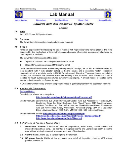
Marvell Nanolab Member login Lab Manual Index Mercury Web <strong>Berkeley</strong> <strong>Microlab</strong><br />
<strong>Edwards</strong> <strong>Auto</strong> <strong>306</strong> <strong>DC</strong> <strong>and</strong> <strong>RF</strong> <strong>Sputter</strong> <strong>Coater</strong><br />
1.0 Title<br />
<strong>Auto</strong> <strong>306</strong> <strong>DC</strong> <strong>and</strong> <strong>RF</strong> <strong>Sputter</strong> <strong>Coater</strong><br />
(edwards)<br />
2.0 Purpose<br />
The <strong>Edwards</strong> system sputters metal <strong>and</strong> dielectric materials<br />
3.0 Scope<br />
Films are deposited by bombarding the target material with high-energy ions from a plasma. The films<br />
deposited by this method are uniform in thickness <strong>and</strong> capable of covering areas usually shadowed by<br />
other deposition methods.<br />
The <strong>Edwards</strong> system consists of two parts:<br />
► Deposition chamber, vacuum system <strong>and</strong> control panel<br />
► <strong>DC</strong> <strong>and</strong> <strong>RF</strong> power supplies <strong>and</strong> MFC control panel<br />
Inside the deposition chamber are two magnetron guns (<strong>DC</strong> on right, <strong>RF</strong> on left, a substrate holder (6inch<br />
st<strong>and</strong>ard, with 4-inch adapter plates), a thermal couple <strong>and</strong> a substrate heater. Maximum<br />
temperature for the substrate heater is 250ºC. Do not exceed this value. The control panel controls the<br />
vacuum, the rotation of the substrate holder <strong>and</strong> heating of the substrate. One mechanical pump is<br />
installed for rough pumping <strong>and</strong> one turbo pump for fine pumping. A crystal monitor is installed in the<br />
system but not currently configured for use.<br />
A <strong>DC</strong> <strong>and</strong> <strong>RF</strong> power supply provides the power needed to generate plasma in the deposition chamber.<br />
4.0 Applicable Documents<br />
Revision History<br />
Description of a basic vacuum system:<br />
http://microlab.berkeley.edu/labmanual/chap6/vacuum.pdf<br />
Vendor manuals: <strong>Edwards</strong> <strong>Auto</strong> <strong>306</strong> <strong>DC</strong> <strong>and</strong> <strong>RF</strong> <strong>Sputter</strong> <strong>Coater</strong>. <strong>Auto</strong> <strong>306</strong> Accessories: Plasmaglo, <strong>DC</strong><br />
<strong>Sputter</strong>ing, Single Bar Glow Discharge, Gold Plated Target, SEM Specimen holder<br />
<strong>and</strong> <strong>Auto</strong> Gas Bleed Kit. <strong>Auto</strong> <strong>306</strong> Accessories: Workholder <strong>and</strong> Heater Accessories.<br />
<strong>Auto</strong> <strong>306</strong> Accessories: Rotary Workholder. Advanced Energy MDX 1.5K Magnetron<br />
Drive. Advanced Energy MDX 1.5K. VM 700-1000-1500 Instruction Manual.<br />
Vendor materials on web: http://www.bocedwards.com/pdf/planar.pdf,<br />
http://www.bocedwards.com/pdf/CoatingSystems_Components.pdf,<br />
http://www.bocedwards.com/pdf/auto<strong>306</strong>em.pdf<br />
5.0 Definitions & Process Terminology<br />
5.1 Deposition Chamber: Contains <strong>DC</strong> <strong>and</strong> <strong>RF</strong> magnetrons, wafer holder, crystal monitor (not<br />
installed yet) <strong>and</strong> heat lamp. The door has a magnetic bearing <strong>and</strong> users should gently close the<br />
door without adding forces on it to assure good seal of the chamber.<br />
5.2 Control Panel: Allows you to vent <strong>and</strong> pump the chamber.<br />
5.3 <strong>DC</strong> power Supply: Middle of the equipment rack to left of deposition chamber. OFF unless<br />
process interlock on.
edwards Chapter 6.07<br />
5.4 <strong>RF</strong> Power Supply: Bottom of the equipment rack to left of deposition chamber. OFF unless<br />
process interlock on.<br />
5.5 Workholder Control: Controls the rotation of the wafers.<br />
5.6 Crystal Monitor (not yet configured): Monitors the evaporation rate by correlating deposited<br />
metal thickness to the amount of deviation from its original crystal resonant frequency.<br />
5.7 <strong>Sputter</strong>ing Materials: Targets available from <strong>Microlab</strong>: Ag, Al, Co, Cr, Cu, In, ITO (90/10%), Ni,<br />
Pd, SiO2, Ti, W. Members may supply their own targets for use in this system after getting<br />
permission by e-mailing <strong>Edwards</strong> at silicon.eecs.berkeley.edu <strong>and</strong> requesting a new sputter<br />
material. Gold, palladium, platinum <strong>and</strong> other precious metal targets will no longer be stocked by<br />
the <strong>Microlab</strong> after the current inventory is exhausted.<br />
5.8 Target: Diameter: 7.5 cm. St<strong>and</strong>ard thickness: 6 mm. Can order from Super Conductor<br />
Materials, Inc. Dielectric materials <strong>and</strong> poor thermal conductors should be ordered indiumbonded<br />
to a 1/16” (~1.5 mm) copper backing plate.<br />
6.0 Safety<br />
6.1 Read all relevant instructions before you operate any accessories.<br />
6.2 Surfaces within the AUTO <strong>306</strong> may hot. Do not touch surfaces without cooling first.<br />
6.3 Intense light will be emitted from the plasma.<br />
6.4 Observe all safety precautions when you come into contact with dangerous substances which<br />
have been used with the evaporation materials.<br />
6.5 Wear clean lint-free gloves when you h<strong>and</strong>le components in the chamber to prevent<br />
contamination of the evaporation materials <strong>and</strong> its accessories.<br />
6.6 Do not add extra forces when you close the chamber door. It will damage the magnetic bearing.<br />
6.7 Metal dust is a hazard. Never use compressed gas to clean the chamber. A house vacuum drop<br />
is available to the right of the chamber.<br />
7.0 Statistical/Process Data<br />
The following recipes (parameter settings/dep rates) provided by Hellman group (Physics) can be used<br />
to sputter different films in the <strong>Edwards</strong> machine (see Tables below (data dated 10/17/06). Please note,<br />
all these recipes use power settings below the cut off limit (350W
edwards Chapter 6.07<br />
8.0 Available Process, Gases, Process Notes<br />
Pumping Speed: < 10 min. to reach process pressure.<br />
Available Targets: Al, Cr, Cu, ITO, Ni, SiO2, Ti, W, Ag, Pd, Co<br />
Precious metal targets, such as gold <strong>and</strong> platinum are not stored by the edwards. Precious metal<br />
targets are available for checkout from the <strong>Microlab</strong> office.<br />
Maximum power for the <strong>Edwards</strong> for any bonded target is 350W.<br />
Note: Maximum allowed power density with dielectric <strong>and</strong> ITO targets is ~2 W/cm 2 (100 W).<br />
For ITO deposition, films with the best conductivity <strong>and</strong> transparency are obtained with a power<br />
density of 1 W/cm 2 for <strong>DC</strong> sputter (~ 50 W) <strong>and</strong> 1.5<br />
W/cm 2 for <strong>RF</strong> sputter (~ 75 W).<br />
Labmembers are cautioned against comparing the <strong>RF</strong> or <strong>DC</strong> power setting of a specific tool in the<br />
MIcrolab to the power setting published in some reference for some other tool. Most references do not<br />
provide any critical tool geometry information (target size <strong>and</strong> distance from source). Power density -<br />
not the absolute setting of the power supply - is the significant variable for determining deposition rate.<br />
For example, on the R<strong>and</strong>ex (another general use sputter tool in the <strong>Microlab</strong>) the target size is 5”<br />
diameter, <strong>and</strong> the maximum allowable power is 1000 W – which also corresponds to a target power<br />
density of about 7W/cm 2 .<br />
Note: Lab members can use process conditions noted in Section 7.0, as a good starting point for their<br />
own process.<br />
9.0 Operating Procedure<br />
9.1 Enable edwards on WAND.<br />
9.2 Check that the “Water Cooling” <strong>and</strong> “Control Cabinet” green interlock lights are ON. Report fault<br />
if not. The “Vacuum System” green interlock light should also be ON if the system was properly<br />
left in st<strong>and</strong>by mode <strong>and</strong> pumped down by the previous user.<br />
9.3 Vent the chamber (press SEAL <strong>and</strong> then VENT). The vacuum interlock will turn off shortly after<br />
the system output reads atmospheric pressure. It will take a little longer for the chamber to be<br />
able to be opened.<br />
9.4 Place targets in the <strong>RF</strong> (front left) or <strong>DC</strong> (back right) magnetrons.<br />
Note: DO NOT TOUCH THE TARGET WHEN IT IS HOT, IMMEDIATELY AFTER<br />
PROCESSING WAFER/S. THIS CAN RESULT IN INJURY AND/OR TARGET<br />
CONTAMINATION (SURGICAL GLOVES CAN EASILY MELT ONTO THE TARGET<br />
SU<strong>RF</strong>ACE).<br />
9.4.1 Open the shutter for the appropriate magnetron. A manual lever on the left h<strong>and</strong> side of<br />
the chamber operates the <strong>RF</strong> shutter <strong>and</strong> the control unit to the right of the chamber<br />
operates the <strong>DC</strong> shutter (SS1 button).<br />
9.4.2 Lift off the target shield cylinder surrounding the magnetron. Care should be taken not to<br />
hit the inside of the chamber as this is being done. The work-holder may need to be<br />
rotated <strong>and</strong> the 4”insert rings removed in order to remove the <strong>DC</strong> cylinder from the<br />
chamber. Sometimes it works best to remove the cylinder through one of the wafer<br />
holder 6” holes.<br />
9.4.3 There are currently two types of target clamp rings used on this tool, the old <strong>and</strong> the new<br />
style clamps. The old design still used on the <strong>RF</strong> gun is a copper clamp that needs to be<br />
tighten down by several screws (torque wrench). The new style clamp is a spring loaded<br />
ring that engages three stationary pins (screws) to hold the target down on top of the<br />
magnetron sputter gun assembly.<br />
9.4.4 Follow the instructions below for Installing or removing a target in <strong>Edwards</strong> machine.<br />
- 3 -
edwards Chapter 6.07<br />
Old Style Screw Holes Ring<br />
Unscrew <strong>and</strong> remove the copper clamp ring on top of the magnetron sputter gun <strong>and</strong><br />
place the target on the top. Use caution when placing magnetic targets onto the sputter<br />
gun. There are strong magnets in the gun that will attract the target <strong>and</strong> this is a pinch<br />
hazard. Replace the copper clamp ring back in place <strong>and</strong> screw it down in a<br />
diagonal/star pattern - a 3 mm metric Allen wrench <strong>and</strong> a 5” lb. torque.<br />
New Style Clamp Down Ring<br />
Rotate the spring loaded copper clamp down ring, counter clockwise to remove it from<br />
top of the <strong>DC</strong> magnetron sputter gun, shown in Figure 1. Place the desired target on top<br />
of the gun, Figure 2. Use caution when placing magnetic targets onto the sputter gun.<br />
There are strong magnets in the gun that will attract the target <strong>and</strong> this is a pinch<br />
hazard. Replace the spring loaded copper clamp ring back in place by rotating it<br />
clockwise to engage the stationery pins on the magnetron sputter gun, Figure 1.<br />
Note: Clamp rings are thickness specific can hold 1/4" <strong>and</strong> 1/8" thick targets. The clamp<br />
ring currently available at the station caters 1/4" targets, therefore proper backing plate<br />
needs to be ordered with expensive sputtering material that would otherwise be too thin<br />
(expensive) to meet above specification, hence, backing plate + target material = 1/4".<br />
9.4.5 Clean off the sputter gun top surfaces to remove any materials from previous runs<br />
(Scotchbrite pads <strong>and</strong> IPA work well for this, wipe with clean-room wipe <strong>and</strong> IPA, pads<br />
are provided in the target storage area above the tool). Pads should remain with the<br />
machine at all times. Inspect the target clamp <strong>and</strong> shield cylinder for excessive material<br />
build up. Report a fault if either needs a thorough cleaning.<br />
9.4.6 Place the cylinder back around the magnetron. If you have the st<strong>and</strong>ard target thickness<br />
of 6 mm, the smallest slot should be used for the <strong>RF</strong> target shield <strong>and</strong> the middle slot<br />
should be used for the <strong>DC</strong> target shield. A st<strong>and</strong>ard 6 mm thick target will have 5 mm<br />
spacing for the shield for <strong>RF</strong> sputtering <strong>and</strong> will have 3 mm spacing for <strong>DC</strong> sputtering. If<br />
your target is a different thickness consult the <strong>Edwards</strong> <strong>Auto</strong> <strong>306</strong> <strong>DC</strong> <strong>and</strong> <strong>RF</strong> <strong>Sputter</strong><br />
<strong>Coater</strong> manual in the <strong>Microlab</strong> office. Magnetic materials need to be much thinner (1-2<br />
mm) <strong>and</strong> should use a Cu backing plate to obtain the overall desired thickness.<br />
9.4.7 Close the shutters once the target is in place. If a target is not being used, the cover<br />
should remain over the shield.<br />
9.5 Once the target is in place, check to make sure that the wafer holder can rotate freely - the<br />
thermocouple needs to clear the rotating holder <strong>and</strong> can easily be moved when changing the<br />
target. Place the wafers in the substrate holder, using the 4-inch wafer converters if necessary.<br />
9.6 If the small cylinder vacuum cap in the front right of the chamber has popped off, replace it in the<br />
correct position.<br />
9.7 Close the chamber door <strong>and</strong> press CYCLE to evacuate the chamber. Pressing cycle evacuates<br />
the chamber without enabling the process interlock.<br />
9.8 When the vacuum is sufficient to begin the sputter process, the PROCESS button will light up on<br />
the vacuum control panel. Press PROCESS to begin the sputter process. Once the process<br />
interlock is enabled, the gas flow controller <strong>and</strong> the <strong>DC</strong> <strong>and</strong> <strong>RF</strong> power supplies are enabled.<br />
Start flow of the Ar/N/O2 gases depending on process parameters.<br />
9.9 Mass Flow Controller (MFC)<br />
9.9.1 Enable Gas 1 (AR) or Gas 2 (O2) by toggling the pneumatic toggle switches just above<br />
the Brooks Controller. The Left toggle switch is for Argon <strong>and</strong> the Right toggle switch is<br />
for Oxygen/Nitrogen. This opens the pneumatic valves only. Either Nitrogen or Oxygen<br />
may be selected by turning the valve below the vacuum control panel.<br />
9.9.2 Set MFC flow at front panel of the Brooks controller. Press the “Channel Selection”<br />
Key until you see “>” symbol after 1 or 2, i.e. “1>” = Gas 1 is Active channel.<br />
- 4 -
edwards Chapter 6.07<br />
9.9.3 Set the desired flow by pressing the “Up” or “Down” arrow keys to your desired flow<br />
setting. The double up arrows increments by 1’s <strong>and</strong> the single up arrow button<br />
increments by .05.<br />
9.9.4 Press “Enter” (the set-point will not be entered until you press enter).<br />
9.9.5 The controller display will automatically cycle back to flow reading within a few seconds.<br />
You should see gas flow at this time. You must be in “Process” mode on the <strong>Edwards</strong> for<br />
gas flow.<br />
Note: PLEASE DO NOT ADJUST ANY OTHER VALUES OTHER THAN GAS SETPOINTS<br />
ON THE BROOKS CONTROLLER.<br />
9.10 Adjust settings for appropriate power supply. Please see applicable documents in Section 4.0 if<br />
process parameters are not already known for your material or consult superuser/<strong>Microlab</strong> staff.<br />
Process data will be supplied in this document once materials have been evaluated.<br />
9.11 <strong>DC</strong> <strong>Sputter</strong>ing – AE MDX-1.5K<br />
9.11.1 Press SETPOINT <strong>and</strong> adjust the set point using the level knob.<br />
9.11.2 Press ACTUAL until watts are shown. Do not exceed 350 Watts for unbacked metal<br />
targets. Targets attached to a backing plate should be limited to 300 Watts or less.<br />
9.11.3 Do not adjust RAMP – the knob should be locked.<br />
9.11.4 Turn on the power supply <strong>and</strong> look for plasma – color will depend on material being<br />
sputtered.<br />
9.12 <strong>RF</strong> <strong>Sputter</strong>ing – AE <strong>RF</strong>X-600<br />
9.12.1 Hold down SETPOINT while adjusting the LEVEL knob to set the sputter power. Do not<br />
exceed 350 Watts for metal targets. Dielectric targets <strong>and</strong> targets attached to a backing<br />
plate should be limited to 300 Watts or less. Use caution with power settings for thermally<br />
sensitive materials.<br />
9.12.2 Make sure that the auto-tuner is set to AUTO.<br />
9.12.3 Turn on the power supply <strong>and</strong> look for plasma – color will depend on material being<br />
sputtered.<br />
9.12.4 Tips for igniting the <strong>RF</strong> plasma<br />
9.12.4.1 Set the Ar pressure to ~20 mTorr <strong>and</strong> turn on the power supply. When the<br />
plasma ignites the Ar pressure can reduced to the desired pressure.<br />
9.12.4.2 Start with a metal target in the <strong>DC</strong> gun <strong>and</strong> ignite the plasma. (The shutter<br />
does not need to be opened.) Turn on the <strong>RF</strong> power supply. The <strong>DC</strong> power<br />
supply may be turned off once the <strong>RF</strong> plasma has ignited.<br />
9.13 Start rotating the wafers. Open shutter <strong>and</strong> start deposition time.<br />
9.14 Once done sputtering, close the shutter, turn off power supply, <strong>and</strong> then stop the wafer rotation.<br />
Set the MFC to zero flow <strong>and</strong> press CYCLE to evacuate the process gas from the chamber. If<br />
the process interlock turns off while sputtering, you will need to extend the time delay for the<br />
interlock. See the Troubleshooting Section for more information.<br />
9.15 Press SEAL <strong>and</strong> then VENT if the process interlock is still enabled. If the time delay set point has<br />
passed <strong>and</strong> the process interlock is disabled <strong>and</strong> only VENT needs to be pressed. Make sure<br />
that the chamber has sufficient time to cool down before venting.<br />
9.16 Wait for the chamber to come up to atmospheric pressure <strong>and</strong> remove wafers from the holder.<br />
System may be hot inside deposition chamber if sputtering times were long.<br />
- 5 -
edwards Chapter 6.07<br />
9.17 Repeat from 0 if additional wafers need to be processed. Otherwise proceed to 9.18.<br />
9.18 Open appropriate shutters <strong>and</strong> remove target(s). Replace ALL covers <strong>and</strong> close the shutters.<br />
Replace vacuum cap. Targets should be returned to their appropriate storage container <strong>and</strong><br />
never be left in the chamber.<br />
9.19 Once all wafers <strong>and</strong> targets have been removed, close the chamber door <strong>and</strong> evacuate the<br />
system by pressing CYCLE.<br />
9.20 Once the system is pumped down, disable the equipment on w<strong>and</strong> <strong>and</strong> provide the following<br />
information in the comment section: material sputtered, gas type <strong>and</strong> flow rates, <strong>DC</strong> or <strong>RF</strong> power,<br />
<strong>and</strong> deposition time (for desired thickness if known). If a previous user had left a target in the<br />
system, please make a note.<br />
10.0 Troubleshooting Guidelines<br />
10.1 Process interlock shuts off.<br />
If the time delay set point is too short <strong>and</strong> the process interlock disables before you are done<br />
sputtering, you can adjust the time by going into the set point-relay menu.<br />
10.1.1 Press NO for main menu, scroll to set point-relay <strong>and</strong> press YES.<br />
10.1.2 Scroll to time delays <strong>and</strong> press YES.<br />
10.1.3 Scroll to time delay 7 (if not already there).<br />
10.1.4 To adjust time, press yes <strong>and</strong> a blinking B should be seen. Using arrow keys, set the first<br />
digit of the desired time <strong>and</strong> press yes. Set the second digit <strong>and</strong> press YES or press YES<br />
again (while B is still blinking) to go the minute/second display. Set to minutes (M) or<br />
seconds (S) <strong>and</strong> press YES to set new time.<br />
10.1.5 Once the new time is set, press NO to exit menus until you reach the main menu. Select<br />
Process Sequence <strong>and</strong> press YES to go back to the normal screen.<br />
10.1.6 Gases are not flowing. If all the appropriate switches are open <strong>and</strong> no gas is flowing<br />
check to make sure edwards is enabled.<br />
10.2 VOLTS ERR is displayed on the vacuum control panel.<br />
This error is displayed when the high vacuum (Penning) gauge has a flake in it. The vacuum<br />
controller will not let you enter the process mode if this condition exists. File a fault on the w<strong>and</strong><br />
to have the gauge cleaned by the process staff.<br />
- 6 -
edwards Chapter 6.07<br />
11.0 Figures & Schematics<br />
Figure 1 - Copper Clam Ring With Springs Holding Down The Target<br />
Figure 2 - Target on <strong>DC</strong> Magnetron <strong>Sputter</strong> Gun<br />
- 7 -
edwards Chapter 6.07<br />
Gas Selection Box<br />
<strong>DC</strong> Power Supply<br />
MFC Controller<br />
Emergency Off Button<br />
Distribution Panel<br />
Matching<br />
Network<br />
Controller<br />
Equipment Rack<br />
<strong>RF</strong> Power<br />
Supply<br />
Rotary Workholder Drive<br />
Workholder<br />
Figure 3 - <strong>Edwards</strong> <strong>Auto</strong> <strong>306</strong> <strong>DC</strong> <strong>and</strong> <strong>RF</strong> <strong>Sputter</strong> <strong>Coater</strong><br />
- 8 -<br />
Deposition Chamber<br />
Magnetron Source<br />
Control Console<br />
Control Cabinet<br />
Reactive Gas<br />
Selection Box
edwards Chapter 6.07<br />
<strong>RF</strong>X - 600<br />
Status LEDs Reflected Power Indicator<br />
Right<br />
Left Digital<br />
Digital Meter<br />
Meter<br />
Output<br />
Enable<br />
Switches<br />
Figure 4 - Control Panel<br />
Output<br />
Level<br />
Control<br />
Power<br />
Display Setup<br />
Switches Regulation Setup<br />
Set Point Enable<br />
Remote<br />
Control<br />
Switches<br />
- 9 -
Digital<br />
Indicator<br />
edwards Chapter 6.07<br />
Setpoint Controls<br />
ENTER<br />
Figure 5 - Distribution Panel<br />
- 10 -<br />
0152E<br />
Channel<br />
Selection<br />
Valve<br />
Open/Close<br />
(not used)<br />
Remote<br />
Control<br />
Power
edwards Chapter 6.07<br />
Figure 6 - <strong>DC</strong> Power Supply<br />
Figure 7 - Rotary Control Panel<br />
- 11 -
edwards Chapter 6.07<br />
Figure 8 - Heater Control Panel<br />
Figure 9 - Shutter Control Panel<br />
- 12 -