coM.sat ISDN Basic UMTS
coM.sat ISDN Basic UMTS
coM.sat ISDN Basic UMTS

Create successful ePaper yourself
Turn your PDF publications into a flip-book with our unique Google optimized e-Paper software.
<strong>coM</strong>.<strong>sat</strong> <strong>ISDN</strong> <strong>Basic</strong> <strong>UMTS</strong><br />
Manual<br />
<strong>coM</strong>.<strong>sat</strong> <strong>ISDN</strong> <strong>Basic</strong> <strong>UMTS</strong><br />
created: page: file:<br />
11/04/07 1 <strong>coM</strong><strong>sat</strong> <strong>ISDN</strong> <strong>Basic</strong> Manual <strong>UMTS</strong>.doc<br />
Note Protection Mark according to DIN 34!
<strong>coM</strong>.<strong>sat</strong> <strong>ISDN</strong> <strong>Basic</strong> <strong>UMTS</strong><br />
Contents<br />
Contents .................................................................................................................................................. 2<br />
List of figures .......................................................................................................................................... 4<br />
Versions................................................................................................................................................... 5<br />
Abbreviations .......................................................................................................................................... 6<br />
Literature references .............................................................................................................................. 8<br />
1 Introduction ..................................................................................................................................... 9<br />
2 User safety information ................................................................................................................ 10<br />
2.1 Electrical safety .................................................................................................................. 10<br />
2.1.1 Air traffic safety ................................................................................................ 10<br />
2.2 Environment with explosive materials ................................................................................ 10<br />
2.3 Road traffic safety .............................................................................................................. 10<br />
2.4 Non-ionising radiation ........................................................................................................ 10<br />
2.5 Electronic medical equipment ............................................................................................ 10<br />
2.6 Measures to be taken in case of loss/theft ........................................................................ 11<br />
2.7 Transport ............................................................................................................................ 11<br />
2.8 Where to install the devices ............................................................................................... 11<br />
2.9 Damage and repairs .......................................................................................................... 11<br />
3 Functional description .................................................................................................................. 12<br />
3.1 Starting up the device ........................................................................................................ 16<br />
3.2 Installation of the <strong>coM</strong><strong>sat</strong>.exe application .......................................................................... 17<br />
3.3 Configuration of the <strong>coM</strong>.<strong>sat</strong> <strong>ISDN</strong> <strong>Basic</strong> <strong>UMTS</strong> ............................................................... 18<br />
3.3.1 Interface ............................................................................................................. 19<br />
3.3.2 <strong>ISDN</strong> Configuration .......................................................................................... 22<br />
3.3.3 GSM Configuration ........................................................................................... 25<br />
3.3.4 Routing .............................................................................................................. 27<br />
3.3.4.1 Routing according to dialled number ................................................ 28<br />
3.3.4.2 Selection of providers by time and number ...................................... 29<br />
3.3.4.3 Callback Table and special routing .................................................. 30<br />
3.3.4.4 Automatically inserted country and area codes ................................ 30<br />
3.3.5 Incoming calls ................................................................................................... 31<br />
3.3.6 Outgoing calls ................................................................................................... 34<br />
3.3.7 Fax/Data ............................................................................................................. 37<br />
3.3.8 Statistics ............................................................................................................ 39<br />
3.3.9 Voice .................................................................................................................. 41<br />
3.3.10 Unconnected Calls ........................................................................................... 43<br />
3.3.11 Diversion ........................................................................................................... 46<br />
3.3.12 Virtual PBX ........................................................................................................ 48<br />
3.3.12.1 General Information .......................................................................... 48<br />
3.3.12.2 Configuration .................................................................................... 49<br />
3.3.12.3 Call Hold ........................................................................................... 50<br />
3.3.12.4 Call Retrieve ..................................................................................... 50<br />
3.3.12.5 Call Transfer ..................................................................................... 50<br />
3.3.12.6 Licensing ........................................................................................... 51<br />
3.3.13 Clock .................................................................................................................. 52<br />
3.3.14 Channel 1/2 ........................................................................................................ 54<br />
3.3.15 Info ..................................................................................................................... 57<br />
3.3.16 SMS .................................................................................................................... 61<br />
3.3.16.1 Receive SMS .................................................................................... 62<br />
3.3.16.2 Send SMS ......................................................................................... 62<br />
3.3.17 Firmware ............................................................................................................ 63<br />
3.3.18 Terminal ............................................................................................................. 65<br />
3.3.19 Monitor Configuration ...................................................................................... 67<br />
3.3.20 Monitor ............................................................................................................... 69<br />
3.3.21 Additional information ..................................................................................... 70<br />
created: page: file:<br />
11/04/07 2 <strong>coM</strong><strong>sat</strong> <strong>ISDN</strong> <strong>Basic</strong> Manual <strong>UMTS</strong>.doc<br />
Note Protection Mark according to DIN 34!
<strong>coM</strong>.<strong>sat</strong> <strong>ISDN</strong> <strong>Basic</strong> <strong>UMTS</strong><br />
3.3.22 Vendor functions .............................................................................................. 71<br />
4 Installation and operating information ........................................................................................ 72<br />
4.1 <strong>coM</strong>.<strong>sat</strong> <strong>ISDN</strong> <strong>Basic</strong> <strong>UMTS</strong> replaces network termination ...................................................... 72<br />
4.2 <strong>coM</strong>.<strong>sat</strong> <strong>ISDN</strong> <strong>Basic</strong> <strong>UMTS</strong> in TE mode .................................................................................. 74<br />
4.3 <strong>coM</strong>.<strong>sat</strong> <strong>ISDN</strong> <strong>Basic</strong> <strong>UMTS</strong> in router mode ............................................................................. 77<br />
4.4 Transmit SMS ......................................................................................................................... 79<br />
4.5 Fax transmission via PC ......................................................................................................... 79<br />
4.5.1 Preparation of the PC for fax transmissions ................................................. 79<br />
4.5.2 Send fax messages .......................................................................................... 80<br />
4.5.3 Receive fax message ....................................................................................... 82<br />
4.6 Data transmission via PC ........................................................................................................ 82<br />
4.6.1 Preparing the PC for the transfer of data ....................................................... 82<br />
4.6.2 Sending and receiving data ............................................................................. 82<br />
4.7 Servicing / Remote servicing .................................................................................................. 82<br />
4.7.1 Servicing ............................................................................................................ 83<br />
4.7.2 Remote servicing .............................................................................................. 83<br />
4.7.3 Read out/Transmit configuration .................................................................... 86<br />
4.7.4 Software update ................................................................................................ 86<br />
5 Questions and answers ................................................................................................................ 87<br />
6 Technical data ............................................................................................................................... 88<br />
6.1 Connector assignments .......................................................................................................... 89<br />
Appendix 1: LED Function ........................................................................................................... 90<br />
Appendix 2: Terminal commands ............................................................................................... 91<br />
created: page: file:<br />
11/04/07 3 <strong>coM</strong><strong>sat</strong> <strong>ISDN</strong> <strong>Basic</strong> Manual <strong>UMTS</strong>.doc<br />
Note Protection Mark according to DIN 34!
<strong>coM</strong>.<strong>sat</strong> <strong>ISDN</strong> <strong>Basic</strong> <strong>UMTS</strong><br />
List of figures<br />
Figure 1: Functional Groups .................................................................................................................. 13<br />
Figure 2: Front side of the <strong>coM</strong>.<strong>sat</strong> <strong>ISDN</strong> <strong>Basic</strong> <strong>UMTS</strong> ......................................................................... 14<br />
Figure 3: Top side of the <strong>coM</strong>.<strong>sat</strong> <strong>ISDN</strong> <strong>Basic</strong> <strong>UMTS</strong> ........................................................................... 15<br />
Figure 4: Rear side of the <strong>coM</strong>.<strong>sat</strong> <strong>ISDN</strong> <strong>Basic</strong> <strong>UMTS</strong> .......................................................................... 15<br />
Figure 5: <strong>coM</strong><strong>sat</strong>.exe Installation ........................................................................................................... 17<br />
Figure 6: Interface ................................................................................................................................. 19<br />
Figure 7: Automatic Load ...................................................................................................................... 21<br />
Figure 8: <strong>ISDN</strong> Configuration ................................................................................................................ 22<br />
Figure 9: GSM Configuration ................................................................................................................. 25<br />
Figure 10: Routing ................................................................................................................................. 27<br />
Figure 11: Incoming calls ....................................................................................................................... 31<br />
Figure 12: Outgoing calls ....................................................................................................................... 34<br />
Figure 13: Fax/Data ............................................................................................................................... 37<br />
Figure 14: Statistics ............................................................................................................................... 39<br />
Figure 15: Voice .................................................................................................................................... 41<br />
Figure 16: Unconnected calls ................................................................................................................ 43<br />
Figure 17: Diversion .............................................................................................................................. 46<br />
Figure 18: Virtual PBX ........................................................................................................................... 48<br />
Figure 19: Clock .................................................................................................................................... 52<br />
Figure 20: Channel 1/2 .......................................................................................................................... 54<br />
Figure 21: Module information ............................................................................................................... 57<br />
Figure 22: Module information in the terminal window .......................................................................... 59<br />
Figure 23: Unlock SIM card ................................................................................................................... 60<br />
Figure 24: Set prepaid credit ................................................................................................................. 60<br />
Figure 25: SMS ...................................................................................................................................... 61<br />
Figure 26: Firmware Update .................................................................................................................. 63<br />
Figure 27: Terminal ............................................................................................................................... 65<br />
Figure 28: Monitor Configuration ........................................................................................................... 67<br />
Figure 29: Trace recording .................................................................................................................... 69<br />
Figure 30: Vendor Functions in channel 1/2.......................................................................................... 71<br />
Figure 31: NT Installation ...................................................................................................................... 72<br />
Figure 32: NT Configuration .................................................................................................................. 73<br />
Figure 33: TE Installation ....................................................................................................................... 75<br />
Figure 34: TE Configuration .................................................................................................................. 76<br />
Figure 35: Router Installation ................................................................................................................ 77<br />
Figure 36: Install modem ....................................................................................................................... 80<br />
Figure 37: Send Fax Wizard .................................................................................................................. 81<br />
Figure 38: Remote Servicing ................................................................................................................. 84<br />
created: page: file:<br />
11/04/07 4 <strong>coM</strong><strong>sat</strong> <strong>ISDN</strong> <strong>Basic</strong> Manual <strong>UMTS</strong>.doc<br />
Note Protection Mark according to DIN 34!
<strong>coM</strong>.<strong>sat</strong> <strong>ISDN</strong> <strong>Basic</strong> <strong>UMTS</strong><br />
Versions<br />
Vers. Date Description of the revision Chapter Amended<br />
No.<br />
by<br />
1.0 15/03/05 First issue All SJ<br />
1.1 11/04/05 Corrections All SJ<br />
1.2 28/06/05 Power supply changed<br />
6 SJ<br />
Progress indicator added<br />
3.3.6<br />
Module information corrected<br />
3.3.15<br />
Windows XP added<br />
1<br />
Fixed network MODEM mentioned 4.7.2<br />
<strong>ISDN</strong> LED description improved 4.1<br />
19/07/05 TE and Router mode described SJ<br />
2.0 06/12/06 Complete review All SJ<br />
2.2 11/04/07 Complete review;<br />
All SJ<br />
Fax/Data via PC<br />
3.3.7, 4.5,<br />
4,6<br />
2.3 17/07/07 VPBX usage option 3.3.12 SJ<br />
2.4 01/08/07 CLIP list 3.3.6 SJ<br />
2.5 21/09/07 Return Call Announcement 3.3.10 SJ<br />
2.6 28/05/08 Optional Sync/Relais board added 3.3.2,4.1,<br />
4.3<br />
SJ<br />
created: page: file:<br />
11/04/07 5 <strong>coM</strong><strong>sat</strong> <strong>ISDN</strong> <strong>Basic</strong> Manual <strong>UMTS</strong>.doc<br />
Note Protection Mark according to DIN 34!
<strong>coM</strong>.<strong>sat</strong> <strong>ISDN</strong> <strong>Basic</strong> <strong>UMTS</strong><br />
Abbreviations<br />
EEPROM Electrical Erasable Programmable Read only Memory:<br />
I<br />
Memory circuit, which can be deleted by applying an electric<br />
voltage.<br />
2 C - Bus Inter - IC Bus<br />
<strong>UMTS</strong> Universal Mobile Telecommunications System<br />
SIM Subscriber Identity Module<br />
SMS Short Message Service<br />
SMSC Short Message Service Centre<br />
<strong>ISDN</strong> Integrated Services Digital Network<br />
TC System Private telecommunications switching system<br />
NT - Mode Network Termination: in this case, the device is operated as a<br />
network terminal (NT), whereby both the electrical and physical<br />
parameters (Layer 1) are adapted as well as the accepting the<br />
data link service and addressing tasks for layers 2 and 3.<br />
TE - Mode Terminal Equipment: In this case the device is operated at the<br />
TC system like a TE2 device i.e. like an <strong>ISDN</strong> - compatible<br />
terminal.<br />
P - P Point - to Point: direct communication between two points in a<br />
network with each other. Communication is solely via this<br />
connection. The point-to-point connection is a variant of the<br />
wiring of the So interface, if only one terminal is available.<br />
PMP Point-to-Multipoint, the point to multipoint connection is the other<br />
variant of the configuration for the S0 bus. In this case several<br />
terminals (max 8) can be connected to the same connection. Of<br />
these 8 devices, 2 can establish a connection at any one time.<br />
S0<br />
The S0 interface is an internationally standardised interface for<br />
<strong>ISDN</strong> installations. This interface is made available by the NTBA<br />
on the line side. On the customer side, the interface is provided<br />
both for the connection of a telecommunications switching<br />
system ( system connection) as well as for the connection of<br />
up to 6 <strong>ISDN</strong> devices ( multiple device port).<br />
EDSS1 Name of the Euro-<strong>ISDN</strong> protocol (European D-channel Signalling<br />
System No 1); was introduced with the transition of national<br />
<strong>ISDN</strong>s to the whole of Europe, whereby a data link protocol was<br />
introduced, which is supported by all the connected states. This<br />
protocol contains the mandatory performance characteristics,<br />
which control the establishment and clearance of a link, as well<br />
as providing several supplements. National network providers<br />
can extend these performance characteristics.<br />
created: page: file:<br />
11/04/07 6 <strong>coM</strong><strong>sat</strong> <strong>ISDN</strong> <strong>Basic</strong> Manual <strong>UMTS</strong>.doc<br />
Note Protection Mark according to DIN 34!
<strong>coM</strong>.<strong>sat</strong> <strong>ISDN</strong> <strong>Basic</strong> <strong>UMTS</strong><br />
AOC Advice of Charge: Performance characteristic of the EDSS1.<br />
Display of the connection charges incurred as tariff units<br />
according to the network provider’s tariff during and at the end of<br />
a link that has been made.<br />
RJ45 RJ45 is the name given to the eight-pole connector technique,<br />
which has a very simple but effectively working configuration.<br />
This connector technique is used in the <strong>ISDN</strong> wire range for the<br />
So connection. The connector is standardised in ISO 8877.<br />
MSN Multiple Subscriber Number multiple subscriber number for a<br />
multiple device connection.<br />
PBX Private Branch Exchange<br />
created: page: file:<br />
11/04/07 7 <strong>coM</strong><strong>sat</strong> <strong>ISDN</strong> <strong>Basic</strong> Manual <strong>UMTS</strong>.doc<br />
Note Protection Mark according to DIN 34!
<strong>coM</strong>.<strong>sat</strong> <strong>ISDN</strong> <strong>Basic</strong> <strong>UMTS</strong><br />
Literature references<br />
Bergmann / Gerhardt Taschenbuch der Telekommunikation<br />
Fachbuchverlag Leipzig<br />
Kanbach / Körber <strong>ISDN</strong> - Die Technik<br />
Hüthig Verlag<br />
created: page: file:<br />
11/04/07 8 <strong>coM</strong><strong>sat</strong> <strong>ISDN</strong> <strong>Basic</strong> Manual <strong>UMTS</strong>.doc<br />
Note Protection Mark according to DIN 34!
<strong>coM</strong>.<strong>sat</strong> <strong>ISDN</strong> <strong>Basic</strong> <strong>UMTS</strong><br />
1 Introduction<br />
<strong>coM</strong>.<strong>sat</strong> <strong>ISDN</strong> <strong>Basic</strong> <strong>UMTS</strong> is a digital mobile phone adaptor (TA) which uses<br />
suitable GSM/<strong>UMTS</strong> modules and SIM cards for voice communications and SMS<br />
transmissions. <strong>coM</strong>.<strong>sat</strong> <strong>ISDN</strong> <strong>Basic</strong> <strong>UMTS</strong> is connected to the external or internal<br />
<strong>ISDN</strong> (S0) - port of an <strong>ISDN</strong> PABX. The <strong>coM</strong>.<strong>sat</strong> <strong>ISDN</strong> <strong>Basic</strong> <strong>UMTS</strong> mobile phone<br />
adaptor can then be accessed from each extension user. Conversely, each extension<br />
connected to the PABX can be reached from GSM/<strong>UMTS</strong> mobile phones at the most<br />
favourable mobile phone tariff via the <strong>coM</strong>.<strong>sat</strong> <strong>ISDN</strong> <strong>Basic</strong> <strong>UMTS</strong> mobile phone<br />
adaptor.<br />
The <strong>coM</strong>.<strong>sat</strong> <strong>ISDN</strong> <strong>Basic</strong> <strong>UMTS</strong> is assembled in a stable housing and is suitable for<br />
installation on horizontal or vertical surfaces.<br />
<strong>coM</strong>.<strong>sat</strong> <strong>ISDN</strong> <strong>Basic</strong> <strong>UMTS</strong> is configured comfortably and user-friendly via the<br />
<strong>coM</strong><strong>sat</strong>.exe Windows application. The devices can also be serviced remotely with<br />
the aid of this application. The application can run under Windows 98®, Windows<br />
2000® and Windows XP® and should run on Windows ME® and Windows Vista®<br />
too.<br />
The performance characteristics, functions and interfaces of <strong>coM</strong>.<strong>sat</strong> <strong>ISDN</strong> <strong>Basic</strong><br />
<strong>UMTS</strong> are described in this document.<br />
Furthermore, this manual also includes information on installation, use and<br />
diagnostics.<br />
Users are explicitly requested to read the user safety information first.<br />
The manufacturer reserves the right to make technical changes that serve the safety<br />
of the device and improve its operation.<br />
Should you have any further technical questions, our hotline is available at<br />
+49(0)180-5-NEEDHELP (+49(0)180-5-633343) 1 .<br />
Additional information is available from <strong>coM</strong>.<strong>sat</strong>'s internet site:<br />
www.com<strong>sat</strong>.de<br />
Please note: This description applies to the <strong>coM</strong><strong>sat</strong>.exe - Windows Application 3.1.0<br />
(and newer versions) as well as the associated firmware for the <strong>coM</strong>.<strong>sat</strong> <strong>ISDN</strong> <strong>Basic</strong><br />
<strong>UMTS</strong> (V1.3.1 and newer).<br />
1<br />
DTMS - only 14 cent per minute from the german fixed telephone network<br />
created: page: file:<br />
11/04/07 9 <strong>coM</strong><strong>sat</strong> <strong>ISDN</strong> <strong>Basic</strong> Manual <strong>UMTS</strong>.doc<br />
Note Protection Mark according to DIN 34!
<strong>coM</strong>.<strong>sat</strong> <strong>ISDN</strong> <strong>Basic</strong> <strong>UMTS</strong><br />
2 User safety information<br />
The following information applies to the <strong>coM</strong>.<strong>sat</strong> <strong>ISDN</strong> <strong>Basic</strong> <strong>UMTS</strong>. As the cellular<br />
engines used in this device are manufactured by Sierra Wireless (MC8775V), we<br />
explicitly refer to this company’s respective safety regulations and operating<br />
manuals.<br />
2.1 Electrical safety<br />
The <strong>coM</strong>.<strong>sat</strong> <strong>ISDN</strong> <strong>Basic</strong> <strong>UMTS</strong> works with a nominal supply voltage of about 10 V.<br />
Furthermore, the device is connected to the S0 local port of TAs. Therefore no further<br />
precautions are required to protect the user against high voltages from this device.<br />
However, it should be noted that the user must ensure that they discharge any static<br />
charge they may have before working on the device.<br />
2.1.1 Air traffic safety<br />
Use of cellular engines in aircraft can impair their navigation systems and interfere<br />
with the mobile radiophone network. Their use has therefore been forbidden by law.<br />
The <strong>coM</strong>.<strong>sat</strong> <strong>ISDN</strong> <strong>Basic</strong> <strong>UMTS</strong> must therefore not be used on board aircraft. Breach<br />
of requirement can cause temporary or complete suspension of the cellular engine<br />
services and / or legal steps to be taken against the offenders.<br />
2.2 Environment with explosive materials<br />
The <strong>coM</strong>.<strong>sat</strong> <strong>ISDN</strong> <strong>Basic</strong> <strong>UMTS</strong> is not approved for use in potentially hazardous<br />
atmospheres. The user is therefore advised not to use the TA close to such areas,<br />
which could be e.g. at petrol stations, in fuel depots, in chemical works or during<br />
blasting. Should this nevertheless be necessary, the user should take steps to<br />
ensure that no risk can occur.<br />
2.3 Road traffic safety<br />
If the devices are used in vehicles that are used in public road traffic, the national<br />
regulations for telephoning in vehicles applicable for the country in which the device<br />
is must be complied with.<br />
2.4 Non-ionising radiation<br />
As in all radio transmission devices, the user should note that it is advisable for<br />
<strong>sat</strong>isfactory use of the devices and safety of the user that the device is only used in<br />
its normal operating position.<br />
2.5 Electronic medical equipment<br />
The operation of radio transmitters, which includes cellular engines, can impair the<br />
function of medical devices that have not been properly shielded. Please ask advice<br />
created: page: file:<br />
11/04/07 10 <strong>coM</strong><strong>sat</strong> <strong>ISDN</strong> <strong>Basic</strong> Manual <strong>UMTS</strong>.doc<br />
Note Protection Mark according to DIN 34!
<strong>coM</strong>.<strong>sat</strong> <strong>ISDN</strong> <strong>Basic</strong> <strong>UMTS</strong><br />
of your doctor or the manufacturer of the medical device.<br />
2.6 Measures to be taken in case of loss/theft<br />
If the <strong>coM</strong>.<strong>sat</strong> <strong>ISDN</strong> <strong>Basic</strong> <strong>UMTS</strong>, the cellular engines or the SIM cards used are lost,<br />
inform your network provider immediately to prevent any misuse.<br />
2.7 Transport<br />
The packaging ex works is designed to protect against mechanical damage and<br />
should be stored for any later transports. To avoid moisture conden<strong>sat</strong>ion, time must<br />
be allowed for the devices to slowly adapt to the ambient temperature (if they have<br />
been stored in an environment with differing temperature) before starting them up.<br />
2.8 Where to install the devices<br />
The devices should be installed so that they are protected against direct sunlight and<br />
heat. This increases both the reliability of the operation of the devices as well as their<br />
service life, as the components used are less thermally stressed.<br />
The devices should also only be used with the power supplies that they are supplied<br />
with or an original spare part.<br />
The cables to the devices should be installed so that they do not cause any physical<br />
risk. Power cables should be installed separate from the signal cables.<br />
The devices should only be installed by adequately trained personnel.<br />
2.9 Damage and repairs<br />
For safety reasons, the device should not be used in case of noticeable damage or if<br />
it has been exposed to moisture.<br />
Repairs to the device should preferably only be carried out by the manufacturer or<br />
their authorised agents. Should this not be possible at any time, the repair must be<br />
carried out by an adequately qualified person, whereby only original parts should be<br />
used.<br />
The device must be disconnected from the voltage supply before each repair.<br />
created: page: file:<br />
11/04/07 11 <strong>coM</strong><strong>sat</strong> <strong>ISDN</strong> <strong>Basic</strong> Manual <strong>UMTS</strong>.doc<br />
Note Protection Mark according to DIN 34!
<strong>coM</strong>.<strong>sat</strong> <strong>ISDN</strong> <strong>Basic</strong> <strong>UMTS</strong><br />
3 Functional description<br />
The <strong>coM</strong>.<strong>sat</strong> <strong>ISDN</strong> <strong>Basic</strong> <strong>UMTS</strong> connects the telephone system to the GSM/<strong>UMTS</strong><br />
network. The device can be operated both in NT mode as well as TE mode, namely<br />
either as a “point to point“ connection (P - P) or as a “point to multipoint“ (PMP)<br />
connection. It is connected to a local S0 port of the telephone system.<br />
<strong>coM</strong>.<strong>sat</strong> <strong>ISDN</strong> <strong>Basic</strong> <strong>UMTS</strong> is available as a two channel design. It is intended for<br />
use in the GSM/<strong>UMTS</strong> 850/1900/2100MHz network and GSM/GPRS/EDGE<br />
850/900/1800/1900 network, if suitable SIM cards are used.<br />
The use of the Sierra Wireless MC8775V cellular engines not only enables voice<br />
communications, but also the transmission (sending and receiving) of data, faxes and<br />
SMS using a PC and the USB interface for direct access to the cellular engines. The<br />
most important user facilities of the TA are:<br />
GSM/<strong>UMTS</strong> services:<br />
TS11 Voice, full rate and enhanced full rate, DTMF<br />
TS12 Emergency call function<br />
TS21 SMS, text and PDU mode<br />
Supporting services:<br />
CLIP Calling Line Identification Presentation<br />
CLIR Calling Line Identification Restriction<br />
CFU Call Forwarding Unconditional<br />
AoC Advice of Charge<br />
BAOC Block All Outgoing Calls<br />
BOIC Block Outgoing International Calls<br />
BAIC Block All Incoming Calls<br />
COLP Connected Line Identification Presentation<br />
Hardware interfaces:<br />
USB For programming and SMS<br />
RJ45 for connection to the TC system ISO 8877<br />
RJ45 for the synchroni<strong>sat</strong>ion port and <strong>ISDN</strong> network ISO 8877<br />
Cardholder for small 3V SIM cards<br />
SMA RF links for the GSM/<strong>UMTS</strong> antennas<br />
Power Supply Connector<br />
LEDs for displaying the operating condition<br />
Programming:<br />
Configuration of the device settings via the Windows application <strong>coM</strong><strong>sat</strong>.exe<br />
Remote servicing for changes to the programming, software updates, and traces<br />
Setting NT/TE mode via the configuration<br />
Call charge information can be set between 0 and 240 seconds<br />
Comfort suffix dialling (post selection dialling; positive and negative list)<br />
Channel analysis and output of the signal quality<br />
created: page: file:<br />
11/04/07 12 <strong>coM</strong><strong>sat</strong> <strong>ISDN</strong> <strong>Basic</strong> Manual <strong>UMTS</strong>.doc<br />
Note Protection Mark according to DIN 34!
<strong>coM</strong>.<strong>sat</strong> <strong>ISDN</strong> <strong>Basic</strong> <strong>UMTS</strong><br />
Loudness adjustment<br />
To realise the above features, a microprocessors switching has been developed<br />
which controls the interaction of the various functional groups of <strong>coM</strong>.<strong>sat</strong> <strong>ISDN</strong> <strong>Basic</strong><br />
<strong>UMTS</strong>.<br />
These are illustrated in the following sketch.<br />
SIM<br />
USB<br />
GSM -<br />
Module 1<br />
Figure 1: Functional Groups<br />
TE/<br />
Sync NT LED DC IN<br />
<strong>coM</strong>.s.a.t. <strong>ISDN</strong> <strong>Basic</strong><br />
Mainboard<br />
GSM -<br />
Module 2<br />
created: page: file:<br />
11/04/07 13 <strong>coM</strong><strong>sat</strong> <strong>ISDN</strong> <strong>Basic</strong> Manual <strong>UMTS</strong>.doc<br />
Note Protection Mark according to DIN 34!<br />
SIM SIM<br />
SIM
<strong>coM</strong>.<strong>sat</strong> <strong>ISDN</strong> <strong>Basic</strong> <strong>UMTS</strong><br />
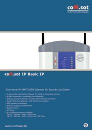
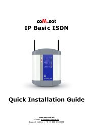
Figure 2: Front side of the <strong>coM</strong>.<strong>sat</strong> <strong>ISDN</strong> <strong>Basic</strong> <strong>UMTS</strong><br />
On the front side are located:<br />
the connector for the power supply<br />
2 SIM card readers<br />
the connector for the USB port (USB-B)<br />
the jack for the NT connection (RJ-45)<br />
the jack for the TE connection or the synchroni<strong>sat</strong>ion (RJ45)<br />
created: page: file:<br />
11/04/07 14 <strong>coM</strong><strong>sat</strong> <strong>ISDN</strong> <strong>Basic</strong> Manual <strong>UMTS</strong>.doc<br />
Note Protection Mark according to DIN 34!
<strong>coM</strong>.<strong>sat</strong> <strong>ISDN</strong> <strong>Basic</strong> <strong>UMTS</strong><br />
Figure 3: Top side of the <strong>coM</strong>.<strong>sat</strong> <strong>ISDN</strong> <strong>Basic</strong> <strong>UMTS</strong><br />
On the top side, there are the LED control indicators.<br />
Figure 4: Rear side of the <strong>coM</strong>.<strong>sat</strong> <strong>ISDN</strong> <strong>Basic</strong> <strong>UMTS</strong><br />
On the rear side, there are the two RF- (SMA) connectors for the antennas, with<br />
antennas screwed in.<br />
created: page: file:<br />
11/04/07 15 <strong>coM</strong><strong>sat</strong> <strong>ISDN</strong> <strong>Basic</strong> Manual <strong>UMTS</strong>.doc<br />
Note Protection Mark according to DIN 34!
<strong>coM</strong>.<strong>sat</strong> <strong>ISDN</strong> <strong>Basic</strong> <strong>UMTS</strong><br />
The connections and significance of the LED’s are labelled to prevent errors.<br />
Before starting up the device, the SIM cards must be inserted into the provided<br />
holders. Two 3V SIM cards are required for full channel availability, but usage with<br />
one SIM card is possible.<br />
To insert the SIM cards in the device, first push in the round yellow button next to the<br />
cardholder with a blunt, thin tool and then remove the cardholder. The SIM card is<br />
then placed in the cardholder and inserted into the card reader together with its<br />
holder. The contact area of the cardholder must be facing the rear of the device.<br />
Attention: When pushing in the card, ensure that it does not fall out of the cardholder<br />
and that the card is correctly inserted in the cardholder guides. The device requires<br />
3V SIM cards for operation!<br />
3.1 Starting up the device<br />
The SIM cards should be inserted into their reader slot first. Then the necessary<br />
cables are connected: Connection to the TC system as NT or TE, a connection to the<br />
PC's USB port on which the <strong>coM</strong><strong>sat</strong>.exe application is installed, and finally the<br />
antenna cables.<br />
Note 1: The GSM/<strong>UMTS</strong> modules used in the <strong>coM</strong>.<strong>sat</strong> <strong>ISDN</strong> <strong>Basic</strong> <strong>UMTS</strong> for<br />
communication via the GSM/<strong>UMTS</strong> network operate with an internal voltage of 3V.<br />
Therefore, for proper operation, SIM cards that can still operate with a working<br />
voltage of 3V must be used. All new SIM cards usually fulfil this requirement. If older<br />
cards (designed for a voltage of 5V) are used, the device possibly cannot log into the<br />
network - despite input of the correct PIN - because the SIMs cannot operate<br />
correctly at a voltage they weren't designed for.<br />
Note 2: When looking at the front of the device, the left-hand SIM card is assigned to<br />
channel 1 and the right-hand card to channel 2.<br />
Once it has been installed, the device can be switched on by inserting the power<br />
jack. This is indicated by the green LED which is labelled “Power“.<br />
All the relevant parameters in the device are deleted in the factory before delivering<br />
the <strong>coM</strong>.<strong>sat</strong> <strong>ISDN</strong> <strong>Basic</strong> <strong>UMTS</strong>, so that it must be set for the individual installation.<br />
Therefore, when installing the TA for the first time, it must be configured using the<br />
<strong>coM</strong><strong>sat</strong>.exe application. To do this, a USB data link must be established between the<br />
<strong>coM</strong>.<strong>sat</strong> <strong>ISDN</strong> <strong>Basic</strong> <strong>UMTS</strong> and the PC on which the application is installed.<br />
created: page: file:<br />
11/04/07 16 <strong>coM</strong><strong>sat</strong> <strong>ISDN</strong> <strong>Basic</strong> Manual <strong>UMTS</strong>.doc<br />
Note Protection Mark according to DIN 34!
<strong>coM</strong>.<strong>sat</strong> <strong>ISDN</strong> <strong>Basic</strong> <strong>UMTS</strong><br />
3.2 Installation of the <strong>coM</strong><strong>sat</strong>.exe application<br />
The <strong>coM</strong><strong>sat</strong>.exe Windows® application is used to configure the <strong>coM</strong>.<strong>sat</strong> <strong>ISDN</strong> <strong>Basic</strong><br />
<strong>UMTS</strong>. It is copied into a suitable directory on a PC together with two text files:<br />
Figure 5: <strong>coM</strong><strong>sat</strong>.exe Installation<br />
The <strong>coM</strong><strong>sat</strong>.exe application can now be executed from this directory or via a<br />
symbolic link that can be created manually e.g. on the desktop. A free USB port on<br />
the PC is required for operation with the <strong>coM</strong>.<strong>sat</strong> <strong>ISDN</strong> <strong>Basic</strong> <strong>UMTS</strong>.<br />
<strong>coM</strong><strong>sat</strong>.exe needs a virtual COM port to access the <strong>ISDN</strong> <strong>Basic</strong> <strong>UMTS</strong>. To install it,<br />
the current user must have administrator rights and the contents of the FTDI folder<br />
must be stored in a suitable directory. If the <strong>ISDN</strong> <strong>Basic</strong> <strong>UMTS</strong> is attached to the PC<br />
for the first time, the Windows® hardware assistant automatically reports a new<br />
device. It asks for the installation files contained in the FTDI folder. After installation<br />
is completed, a new virtual COM port has been added, e.g. COM3. This port must be<br />
used in <strong>coM</strong><strong>sat</strong>.exe.<br />
The virtual device driver is supplied by Future Technology Devices International Ltd.,<br />
the manufacturer of the USB/RS 232 converter used in the <strong>ISDN</strong> <strong>Basic</strong> <strong>UMTS</strong>. If<br />
another driver is required, it can be obtained from www.ftdichip.com. The driver for<br />
FT232BM must be used. The following four files in the FDTI distribution must be<br />
replaced by those shipped with the <strong>ISDN</strong> <strong>Basic</strong> <strong>UMTS</strong>:<br />
FTDIBUS.INF<br />
FTDIPORT.INF<br />
FTDIUN2K.INI<br />
FTDIUNIN.INI<br />
created: page: file:<br />
11/04/07 17 <strong>coM</strong><strong>sat</strong> <strong>ISDN</strong> <strong>Basic</strong> Manual <strong>UMTS</strong>.doc<br />
Note Protection Mark according to DIN 34!
<strong>coM</strong>.<strong>sat</strong> <strong>ISDN</strong> <strong>Basic</strong> <strong>UMTS</strong><br />
3.3 Configuration of the <strong>coM</strong>.<strong>sat</strong> <strong>ISDN</strong> <strong>Basic</strong> <strong>UMTS</strong><br />
The <strong>coM</strong>.<strong>sat</strong> <strong>ISDN</strong> <strong>Basic</strong> <strong>UMTS</strong> is configured with the aid of the <strong>coM</strong><strong>sat</strong>.exe<br />
Windows® application.<br />
After starting the application by double-clicking the application’s icon, the main<br />
application window is opened. Several file cards are displayed which control the<br />
various functions. These are supplemented by the typical Windows® application<br />
menus, such as File, Connection, Configuration, Info, Firmware, Terminal,<br />
Monitor, View, and Help and a symbol bar for quick access to the New, Open,<br />
Save, Login, Logout, Load/Save Configuration, Load Monitor, Load Status and<br />
About commands.<br />
Various function groups are arranged on the file cards so that they form meaningful<br />
units. These are:<br />
Interface<br />
<strong>ISDN</strong> Cfg<br />
GSM/<strong>UMTS</strong> Cfg<br />
Routing<br />
Incoming Calls<br />
Outgoing Calls<br />
Fax / Data<br />
Statistics<br />
Voice<br />
Unconnected Calls<br />
Diversion<br />
Virtual PBX<br />
Clock<br />
Channel 1<br />
Channel 2<br />
Info<br />
SMS<br />
Diversion<br />
Firmware<br />
Terminal<br />
Monitor Cfg<br />
Monitor<br />
Note: The statistics, voice announcement, unconnected calls and diversion functions<br />
are only activated if there is a valid <strong>Basic</strong> Pro license (see 3.3.15). The virtual PBX<br />
functions are only activated if there is a valid virtual PBX license (see 3.3.12.6).<br />
created: page: file:<br />
11/04/07 18 <strong>coM</strong><strong>sat</strong> <strong>ISDN</strong> <strong>Basic</strong> Manual <strong>UMTS</strong>.doc<br />
Note Protection Mark according to DIN 34!
<strong>coM</strong>.<strong>sat</strong> <strong>ISDN</strong> <strong>Basic</strong> <strong>UMTS</strong><br />
3.3.1 Interface<br />
Figure 6: Interface<br />
After calling up the <strong>coM</strong><strong>sat</strong>.exe application, the connection to the device is made via<br />
the "Interface" tab. Upon clicking the tab marked "Interface" it will come to the<br />
foreground and its contents will become visible.<br />
The PC interface which shall be used for the data link to the <strong>coM</strong>.<strong>sat</strong> <strong>ISDN</strong> <strong>Basic</strong><br />
<strong>UMTS</strong> is selected using the "COM port" drop down list box. It is also possible to let<br />
the application choose the port itself, using the "search" button. Should the<br />
application be unable to find a connected <strong>coM</strong>.<strong>sat</strong> <strong>ISDN</strong> <strong>Basic</strong> <strong>UMTS</strong>, it will issue the<br />
message "No device found!".<br />
created: page: file:<br />
11/04/07 19 <strong>coM</strong><strong>sat</strong> <strong>ISDN</strong> <strong>Basic</strong> Manual <strong>UMTS</strong>.doc<br />
Note Protection Mark according to DIN 34!
<strong>coM</strong>.<strong>sat</strong> <strong>ISDN</strong> <strong>Basic</strong> <strong>UMTS</strong><br />
Many functions require an authentication of the user. This is done by clicking on the<br />
"Login" button also located on this tab. The authentication is removed by clicking the<br />
"Logout" button. The termination of <strong>coM</strong><strong>sat</strong>.exe automatically removes<br />
authentication. Therefore explicit logout is only required if <strong>coM</strong><strong>sat</strong>.exe remains<br />
connected to the <strong>ISDN</strong> <strong>Basic</strong> <strong>UMTS</strong> after the user leaves it.<br />
To prevent unauthorised persons from logging into the TA and altering the<br />
configuration, at least the configuration password should be entered in the<br />
“Password“ box. Each password consists of max. 19 alphanumeric characters. The<br />
various function groups within the <strong>coM</strong>.<strong>sat</strong> <strong>ISDN</strong> <strong>Basic</strong> <strong>UMTS</strong> <strong>coM</strong><strong>sat</strong>.exe<br />
application are then accessible with differing protection.<br />
Users who do not know either of these passwords can carry out all the unprotected<br />
functions on the device. They connect to the device by calling up “Connection” on<br />
the menu bar and calling up ”Go Online” in the menu that opens, or simply use the<br />
desired function. The applications then connects to the <strong>coM</strong>.<strong>sat</strong> <strong>ISDN</strong> <strong>Basic</strong> <strong>UMTS</strong>.<br />
In this mode, the device configuration can be read, but not altered. SMS can be sent<br />
and received and any SMS received can also be read. The same procedure applies<br />
to remote access to the device.<br />
However, the configuration settings can only be altered by logging in with a<br />
configuration password. Then all configuration data can be read out, amended and<br />
resaved. The ”Vendor Functions” password makes further functional blocks<br />
accessible, via which the various network operators can be authorised or excluded.<br />
If a password is entered, this password is transferred to the TA together with the<br />
configuration data. The next time the TA is logged into, the password must first be<br />
entered in the relevant box.<br />
A password can be deleted or altered after logging in by deleting the relevant box for<br />
the password or entering another password. The new password is then valid after the<br />
next update of the configuration.<br />
The configuration data of one or several devices can be saved as usual in<br />
Windows®. The files contain the configuration, the firmware ID, the device<br />
information and the monitor contents, if these have been loaded before.<br />
At the bottom of the <strong>coM</strong><strong>sat</strong>.exe window there is a state bar which displays the<br />
current actions. The state of the link (online/offline) and the port of the PC via which<br />
the data is transmitted when a link is made (e.g. “Online (COM 1)”) is displayed on<br />
the left-hand side of the bar.<br />
The ”Connection” menu contains another command, i.e. ”Automatic Load”. This<br />
command opens the following dialog:<br />
created: page: file:<br />
11/04/07 20 <strong>coM</strong><strong>sat</strong> <strong>ISDN</strong> <strong>Basic</strong> Manual <strong>UMTS</strong>.doc<br />
Note Protection Mark according to DIN 34!
<strong>coM</strong>.<strong>sat</strong> <strong>ISDN</strong> <strong>Basic</strong> <strong>UMTS</strong><br />
Figure 7: Automatic Load<br />
As long as this dialog is open, <strong>coM</strong><strong>sat</strong>.exe checks the messages from the device<br />
and starts an automatic load if it reports a restart. The load process can also be<br />
started periodically. To enable this, the option “Load every … minutes” must be<br />
activated and the period set as desired. The automatic load loads the monitor, the<br />
statistics, or both, as selected by the options.<br />
Íf the automatic load is done for monitoring a long period, the load timeout should last<br />
3 – 5 minutes in order not to loose information. If only statistics is loaded, 1 hour is<br />
sufficient. To load the statistics, a login must be possible so the passwords must be<br />
entered correctly. The automatic load function logs in before loading the statistics,<br />
even if already logged in. This is done because a restart might have caused a logout<br />
and then the statistics could not be loaded anymore.<br />
created: page: file:<br />
11/04/07 21 <strong>coM</strong><strong>sat</strong> <strong>ISDN</strong> <strong>Basic</strong> Manual <strong>UMTS</strong>.doc<br />
Note Protection Mark according to DIN 34!
<strong>coM</strong>.<strong>sat</strong> <strong>ISDN</strong> <strong>Basic</strong> <strong>UMTS</strong><br />
3.3.2 <strong>ISDN</strong> Configuration<br />
Figure 8: <strong>ISDN</strong> Configuration<br />
The settings required for operation with the telephone system are made in the "<strong>ISDN</strong><br />
Cfg" tab. When configuring the <strong>ISDN</strong> link, layers 1 to 3 are independently set for<br />
operation of the <strong>coM</strong>.<strong>sat</strong> <strong>ISDN</strong> <strong>Basic</strong> <strong>UMTS</strong> in NT or TE mode.<br />
NT-Mode operation<br />
In this mode the device presents itself to the telephone system as the <strong>ISDN</strong> network<br />
operator's network terminator. The connection to the <strong>coM</strong>.<strong>sat</strong> <strong>ISDN</strong> <strong>Basic</strong> <strong>UMTS</strong> is<br />
set up as a point-to-point or point-to-multipoint connection.<br />
created: page: file:<br />
11/04/07 22 <strong>coM</strong><strong>sat</strong> <strong>ISDN</strong> <strong>Basic</strong> Manual <strong>UMTS</strong>.doc<br />
Note Protection Mark according to DIN 34!
<strong>coM</strong>.<strong>sat</strong> <strong>ISDN</strong> <strong>Basic</strong> <strong>UMTS</strong><br />
If the telephone system additionally has a fixed network connection and it reports too<br />
many errors (frame slips, bit slips), a synchroni<strong>sat</strong>ion may be necessary. These types<br />
of errors are unimportant for voice communications. However, in mostly larger TC<br />
systems with more elaborate trouble shooting procedures, problems can occur during<br />
operation that can cause this “faulty“ port being switched off. This can be avoided by<br />
synchroni<strong>sat</strong>ion. In this case, the synchroni<strong>sat</strong>ion input of the <strong>coM</strong>.<strong>sat</strong> <strong>ISDN</strong> <strong>Basic</strong><br />
<strong>UMTS</strong> is connected directly with the system port (fixed network). The synchroni<strong>sat</strong>ion<br />
clock is then derived from this signal.<br />
If an optional add-on board is employed, it is possible to derive the synchronization<br />
clock from the NT port rather than the synchronization port. The parameter field<br />
labelled "Sync from" defines which port is used for synchronization. If the<br />
synchronization on the NT port is selected, the connected TE device must use a<br />
clock on that port synchronized to another source. Note: Since the presence of the<br />
add-on board is not detected, the parameter field is always enabled in NT mode even<br />
if the add-on board is not employed. See also chapters 4.1 and 4.3.<br />
The PBX number entry also depends on the telephone system. Some systems do not<br />
require an entry here. As the entry of Multiple Subscriber Numbers isn't necessary in<br />
NT-mode, their respective boxes are inactive.<br />
TE-Mode operation<br />
If the <strong>coM</strong>.<strong>sat</strong> <strong>ISDN</strong> <strong>Basic</strong> <strong>UMTS</strong> is to be used in TE-mode, that is like a simple<br />
extension, then click the corresponding radio button for layer 3. Layers 2 and 1 will<br />
automatically be set to TE-mode. In this mode (operating on the telephone system's<br />
internal S0 bus) there is usually a point-to-multipoint connection. Therefore the line<br />
type is automatically set to this type of connection.<br />
It is also often necessary to identify those extensions (Multiple Subscriber Numbers 1<br />
and 2) via which the device is identified by the telephone system. Both GSM/<strong>UMTS</strong><br />
channels may be addressable by the same MSN if supported by the telephone<br />
system. If at least one MSN is empty, the device accepts any called party number<br />
and uses that number for the outgoing call. This means that the MSN is dialled via<br />
GSM/<strong>UMTS</strong>, which is usually not desired. This function is useful if there is a diversion<br />
or VIP number programmed for each possible MSN, so that the MSN is converted<br />
into a valid GSM/<strong>UMTS</strong> number.<br />
If used in TE-mode, as terminal equipment, no synchroni<strong>sat</strong>ion is necessary.<br />
Router operation<br />
If the <strong>coM</strong>.<strong>sat</strong> <strong>ISDN</strong> <strong>Basic</strong> <strong>UMTS</strong> shall be able to route calls from one <strong>ISDN</strong> port to<br />
the other, then activate the box labelled “Allow routing from one <strong>ISDN</strong> port to the<br />
other”. Layers 3, 2 and 1 will automatically be set to NT-mode because this reflects<br />
the setting of the <strong>ISDN</strong> port labelled “NT”. The line type automatically changes to<br />
point-to-point connection. The mode of layers 2 and 1 and the line type may be<br />
changed subsequently, but layer 3 of the NT port remains in NT mode, layers 3 to 1<br />
of the TE port always operate in TE mode, and the line type setting applies to both<br />
ports.<br />
The PBX number entry also depends on the telephone system. Some systems do not<br />
require an entry here. As the entry of Multiple Subscriber Numbers isn't necessary in<br />
router mode, their respective boxes are inactive.<br />
created: page: file:<br />
11/04/07 23 <strong>coM</strong><strong>sat</strong> <strong>ISDN</strong> <strong>Basic</strong> Manual <strong>UMTS</strong>.doc<br />
Note Protection Mark according to DIN 34!
<strong>coM</strong>.<strong>sat</strong> <strong>ISDN</strong> <strong>Basic</strong> <strong>UMTS</strong><br />
The <strong>ISDN</strong> line monitoring is activated via the “Enable <strong>ISDN</strong> Watchdog” option box.<br />
In this case, if faults are registered in the <strong>ISDN</strong> layers 1 or 2, a warm restart is carried<br />
out approx. every 100 seconds.<br />
The “Enable Restart” checkbox defines whether or not the <strong>coM</strong>.<strong>sat</strong> <strong>ISDN</strong> <strong>Basic</strong><br />
<strong>UMTS</strong> sends the telephone system a restart command after a cold start or reset.<br />
Usually this option need not be set. It can be set to terminate any active calls after a<br />
restart of the device, but there are also TC systems that do not react on restart<br />
messages and thus make the <strong>coM</strong>.<strong>sat</strong> <strong>ISDN</strong> <strong>Basic</strong> <strong>UMTS</strong> inaccessible until a timeout<br />
terminates the restart procedure.<br />
The country and area code are set in separate input boxes. The country code is the<br />
international dialling prefix (e.g. “+49”). The area code is usually the prefix for phone<br />
numbers in the same town that the TA is located and is therefore omitted when<br />
calling a number in the same area (e.g. “06204”). Entering these numbers at this<br />
point saves you the effort of entering them during later definitions of number lists<br />
(e.g. Net Access Numbers).<br />
If not otherwise specified, the <strong>ISDN</strong> <strong>Basic</strong> <strong>UMTS</strong> assumes that international calls<br />
start with “00” (or “+”) and national calls start with “0”. These settings can be modified<br />
by appending the correct setting to the country and area code separated with a slash<br />
(e.g. “+1/011” as country code and “…/1” as area code for USA and Canada).<br />
The current configuration of the <strong>coM</strong>.<strong>sat</strong> <strong>ISDN</strong> <strong>Basic</strong> <strong>UMTS</strong> can be enquired by<br />
clicking on “Configuration“ in the menu bar and then selecting “Query“ from the<br />
menu. Alternatively, the short cut keys<br />
<br />
and<br />
<br />
can be used or the button “Query Configuration” in the toolbar can be pushed.<br />
After entering a new configuration or altering the current configuration, this can be<br />
saved via the “File“ menu or can be transferred to the <strong>coM</strong>.<strong>sat</strong> <strong>ISDN</strong> <strong>Basic</strong> <strong>UMTS</strong> via<br />
the USB data link. This is done either via “Update“ in the “Configuration“ menu or<br />
by pushing the toolbar button “Update Configuration” or by entering the relevant keys<br />
on the keyboard.<br />
A configuration file that has already been stored can be loaded again using the file<br />
menu and transferred to the device as described.<br />
created: page: file:<br />
11/04/07 24 <strong>coM</strong><strong>sat</strong> <strong>ISDN</strong> <strong>Basic</strong> Manual <strong>UMTS</strong>.doc<br />
Note Protection Mark according to DIN 34!
<strong>coM</strong>.<strong>sat</strong> <strong>ISDN</strong> <strong>Basic</strong> <strong>UMTS</strong><br />
3.3.3 GSM Configuration<br />
Figure 9: GSM Configuration<br />
This page is used to configure GSM/<strong>UMTS</strong> specific options.<br />
The <strong>coM</strong>.<strong>sat</strong> <strong>ISDN</strong> <strong>Basic</strong> <strong>UMTS</strong> implements a time based supervision of prepaid<br />
credits. The credits themselves are dynamically programmed using the command<br />
“Set Prepaid Time“ in menu “Info“, which is described in chapter 3.3.15. Each<br />
channel is programmed a separate threshold, see chapter 3.3.14. If the credit falls<br />
below that threshold, the channel is not used anymore. The GSM/<strong>UMTS</strong><br />
configuration on this page configures additional behaviour in this case.<br />
A GSM/<strong>UMTS</strong> phone number can be programmed which shall receive an SMS if the<br />
credit becomes low. If no number is programmed, no SMS is sent. If a number is<br />
created: page: file:<br />
11/04/07 25 <strong>coM</strong><strong>sat</strong> <strong>ISDN</strong> <strong>Basic</strong> Manual <strong>UMTS</strong>.doc<br />
Note Protection Mark according to DIN 34!
<strong>coM</strong>.<strong>sat</strong> <strong>ISDN</strong> <strong>Basic</strong> <strong>UMTS</strong><br />
programmed, the second input field determines which text is sent with the SMS. This<br />
text allows three place holders:<br />
: Is replaced by the number of the channel with low credit<br />
: Is replaced by the remaining time credit<br />
: Is replaced with the programmed threshold<br />
The VIP number list “VIP numbers” contains GSM/<strong>UMTS</strong> phone numbers that get a<br />
special treatment. Each line contains a phone number and may also contain an MSN<br />
in the format /. The MSN may be used to define short<br />
numbers for the members of the VIP list. If this MSN is called from any source (i.e.<br />
NT, TE or GSM/<strong>UMTS</strong>), the call is connected to the associated GSM/<strong>UMTS</strong> phone<br />
number. If a call comes in from a VIP number, the associated MSN is transmitted as<br />
calling party number in the <strong>ISDN</strong> messages.<br />
VIP users always have the right to dial in even if the channel’s dial in option is<br />
switched off (“Call Default”, see 3.3.14). This allows to define a specific user group<br />
that may dial any number while normal users only call the default extension.<br />
VIP users also use the routing function (see 3.3.4). While normal users calling from<br />
GSM/<strong>UMTS</strong> are always connected to the PBX, VIP users may also call to PSTN or<br />
GSM/<strong>UMTS</strong> depending on the called number and the programmed routing.<br />
If a VIP number is called, the calling party number (the number belonging to the SIM<br />
card) is always shown to the VIP user, even if the channel in use has the option CLIR<br />
enabled, thus suppressing the number presentation. This does not enable the use of<br />
the return call handling in this case, because then a VIP won’t be able to use the<br />
VPBX anymore if a return call is stored for him.<br />
The functions of the virtual PBX are also accessible to VIP users (see 3.3.12). Thus<br />
all GSM/<strong>UMTS</strong> users contained in this list can use all functions normally available<br />
only to PBX extensions. Therefore these phone numbers are also called virtual<br />
extensions.<br />
Note: The device uses the country and area code settings for the GSM/<strong>UMTS</strong><br />
number so that only one notation of a number need to be entered in the list.<br />
created: page: file:<br />
11/04/07 26 <strong>coM</strong><strong>sat</strong> <strong>ISDN</strong> <strong>Basic</strong> Manual <strong>UMTS</strong>.doc<br />
Note Protection Mark according to DIN 34!
<strong>coM</strong>.<strong>sat</strong> <strong>ISDN</strong> <strong>Basic</strong> <strong>UMTS</strong><br />
3.3.4 Routing<br />
Figure 10: Routing<br />
created: page: file:<br />
11/04/07 27 <strong>coM</strong><strong>sat</strong> <strong>ISDN</strong> <strong>Basic</strong> Manual <strong>UMTS</strong>.doc<br />
Note Protection Mark according to DIN 34!
<strong>coM</strong>.<strong>sat</strong> <strong>ISDN</strong> <strong>Basic</strong> <strong>UMTS</strong><br />
3.3.4.1 Routing according to dialled number<br />
The table “Routing Destination for Number Prefixes“ determines if GSM/<strong>UMTS</strong> (with<br />
or without provider) or <strong>ISDN</strong> (with or without provider) is to be used. Special cases<br />
also require the setting of a routing for calls to the PBX (with or without provider).<br />
Example:<br />
Number Prefix Routing<br />
017, 016, 015 GSM/<strong>UMTS</strong>, <strong>ISDN</strong><br />
089 <strong>ISDN</strong><br />
0049 <strong>ISDN</strong> with Provider<br />
<strong>ISDN</strong><br />
This table is parsed from top to bottom, comparing the prefix with the called number.<br />
If the number’s first digits match the given prefix, the routing is evaluated. If<br />
“GSM/<strong>UMTS</strong>” is specified, a GSM/<strong>UMTS</strong> channel is selected according to the “Net<br />
Access Numbers“ settings, optionally inserting a provider. If “<strong>ISDN</strong>” is specified, the<br />
call is routed to PSTN, again allowing the insertion of a provider prefix, just like the<br />
specification of “PBX” which causes a routing to the TC system. If more than one<br />
route ia specified and the first one is not able to route to call, the second option is<br />
evaluated. If e.g. “GSM/<strong>UMTS</strong>,<strong>ISDN</strong>” is specified and there is no GSM/<strong>UMTS</strong><br />
channel available at the moment, the call is routed to <strong>ISDN</strong> (“fallback”). If in this case<br />
only “GSM/<strong>UMTS</strong>” would have been specified, the call would be rejected.<br />
The example above causes the following behaviour:<br />
All calls to typical (german) GSM/<strong>UMTS</strong> numbers are routed via GSM/<strong>UMTS</strong> if<br />
possible, and via <strong>ISDN</strong> otherwise<br />
All calls to Munich (089) are routed via PSTN without provider prefix<br />
All other calls to german numbers (+49) are routed via PSTN with a provider<br />
prefix<br />
All other calls are routed via PSTN without provider<br />
In addition to numbers, the place holder “?“ can be used to specify any number. This<br />
is especially useful if numbers can only be distinguished by their length. This applies<br />
e.g. to internal MSNs and local area numbers. The following example assumes that<br />
all internal MSNs are two digits long:<br />
Number Prefix Routing<br />
017, 016, 015 GSM/<strong>UMTS</strong><br />
??? <strong>ISDN</strong><br />
?? PBX<br />
This routing table works like this: All GSM/<strong>UMTS</strong> numbers are routed via<br />
GSM/<strong>UMTS</strong>. If any number with only two digits is dialled, only the entry number 3<br />
matches, because all other entries require at least 3 digits. All numbers with more<br />
than two digits not matching the first line are routed to the <strong>ISDN</strong> network.<br />
created: page: file:<br />
11/04/07 28 <strong>coM</strong><strong>sat</strong> <strong>ISDN</strong> <strong>Basic</strong> Manual <strong>UMTS</strong>.doc<br />
Note Protection Mark according to DIN 34!
<strong>coM</strong>.<strong>sat</strong> <strong>ISDN</strong> <strong>Basic</strong> <strong>UMTS</strong><br />
The table is split into two columns and the entries are directly edited in the list box. A<br />
double click on an entry makes it editable. By using the “Page Up” and “Page Down”<br />
keys, the edit field can be moved to the next or previous column. The cursor up and<br />
down keys move the edit field one line up or down in the same column.<br />
If the list box has the input focus but no entry is edited, the insert key allows to create<br />
a new line above the first currently selected line. All selected lines can be deleted<br />
using the delete key. Ctrl-C copies selected lines to the clipboard just like Ctrl-X<br />
which also removes the lines afterwards. Ctrl-V inserts lines from the clipboard above<br />
the first selection or at the bottom of the table if none is selected. A selection can be<br />
removed by left click with pressed control key as usual in multiple selection list boxes.<br />
Tab and shift-tab can be used to jump to the next or previous dialog element, as<br />
usual.<br />
The second column only allows to use the keys “i”, “g”, “p”, “v”, “x”, “y”, backspace,<br />
cursor left/right and delete. “i” inserts “<strong>ISDN</strong>”, “g” inserts “GSM/<strong>UMTS</strong>” and “x” inserts<br />
“PBX” at the current insert position. “p”, “v” and “y” do the same with the option of<br />
inserting a provider prefix. The cursor can only be positioned at the beginning and<br />
end of words. Delete and backspace always delete complete words.<br />
Empty lines are removed automatically before the configuration is updated.<br />
3.3.4.2 Selection of providers by time and number<br />
The table “Provider Prefixes to be used“ defines which provider should be used for<br />
those numbers that are routed with provider specified in the first table. This table is<br />
ignored otherwise.<br />
Example:<br />
Time Number Prefix Provider Prefix<br />
9:00 – 18:00, 20:00 – 22:00 0241,0621 01021<br />
9:00 – 12:00 01033<br />
12:00 – 18:00 01013<br />
18:00 – 20:00 01051<br />
0:00 – 24:00 01070<br />
This table is parsed from top to bottom, comparing the current time to the times<br />
specified in the first column and the called number to the prefix in the second column.<br />
An empty entry in the number prefix column matches any number. If both entries<br />
match, the provider specified in this line is used.<br />
The first line in this example defines a specific prefix for specific area codes. The last<br />
line in this example causes all numbers not matching one of the entries above to be<br />
routed using the prefix 01070.<br />
If no entry matches, the call is rejected.<br />
created: page: file:<br />
11/04/07 29 <strong>coM</strong><strong>sat</strong> <strong>ISDN</strong> <strong>Basic</strong> Manual <strong>UMTS</strong>.doc<br />
Note Protection Mark according to DIN 34!
<strong>coM</strong>.<strong>sat</strong> <strong>ISDN</strong> <strong>Basic</strong> <strong>UMTS</strong><br />
This table is displayed in three columns that are edited the same way as the first<br />
table, except that there is no special editing as in the second column of the first table.<br />
3.3.4.3 Callback Table and special routing<br />
The last table on this page, which is only activated if there is a valid <strong>Basic</strong> Pro license<br />
(see 3.3.15), allows to call back special GSM/<strong>UMTS</strong> numbers on request. The<br />
callback can be initiated either by a call (which is rejected) or by an SMS, depending<br />
on which method is allowed in the columns “Call“ and “SMS“ by entering “yes“. If a<br />
callback by SMS is allowed, it is sufficient to receive an SMS from that GSM/<strong>UMTS</strong><br />
number. If the SMS contains a number, it is stored as desired number to be called.<br />
If the callback is accepted by the GSM/<strong>UMTS</strong> user, he usually gets a dial tone and<br />
can dial a number to one of the allowed destinations. If the channel used does not<br />
allow dialling (“Call Default“), there is no dial tone and the call is forwarded to the<br />
number configured in column “Forward to“. If the callback was done due to a<br />
received SMS and the SMS contained a number, there is no dial tone either and that<br />
number is called.<br />
If one (and only one) line has an empty “Calling Number“, this line matches any call<br />
without CLIP. These callers never get a dial tone but are always forwarded to the<br />
number configured in column “Forward to“.<br />
This table can also be used to configure a default number different from that in the<br />
channel settings. The number configured in column “Forward to“ supersedes the<br />
number of the channel settings and is called if that special GSM/<strong>UMTS</strong> user is calling<br />
and nothing is dialled or dialling is not allowed. This is also true if no callback is<br />
allowed, so that the entry only assigns a different default number.<br />
Additionally, the table can prevent certain callers from calling specific destinations. If<br />
a calling party number matches an entry in the callback table, those destinations in<br />
the routing table not allowed by this entry are removed from the possible routes.<br />
3.3.4.4 Automatically inserted country and area codes<br />
The own country and area code is programmable on the dialog page named “<strong>ISDN</strong><br />
Cfg“. This enables the router to find matches in the tables even if the table entries are<br />
specified with these codes and called numbers are lacking them. It is also possible to<br />
specify the tables without these codes and called numbers with these codes will still<br />
match. This eliminates the need for specifying all possible number representations.<br />
created: page: file:<br />
11/04/07 30 <strong>coM</strong><strong>sat</strong> <strong>ISDN</strong> <strong>Basic</strong> Manual <strong>UMTS</strong>.doc<br />
Note Protection Mark according to DIN 34!
<strong>coM</strong>.<strong>sat</strong> <strong>ISDN</strong> <strong>Basic</strong> <strong>UMTS</strong><br />
3.3.5 Incoming calls<br />
Figure 11: Incoming calls<br />
The configuration for incoming GSM/<strong>UMTS</strong> network calls is set up via the “Incoming<br />
calls“ card. First set up how ”Calls without CLIP” are dealt with. These calls can<br />
either be transferred to a particular extension (”Call Default No. ”), which is<br />
determined during configuration of the GSM/<strong>UMTS</strong> channels, or rejected, or dealt<br />
with in the same way as all other calls (”Not Special”).<br />
The dial in behaviour on calls from GSM/<strong>UMTS</strong> is further specified by the option<br />
”Dialling Mode. Overlapped” means that incoming calls are immediately reported to<br />
the PBX without any dial information. The PBX requests more information and the<br />
call is connected. Each dialled digit is immediately forwarded to the PBX which<br />
created: page: file:<br />
11/04/07 31 <strong>coM</strong><strong>sat</strong> <strong>ISDN</strong> <strong>Basic</strong> Manual <strong>UMTS</strong>.doc<br />
Note Protection Mark according to DIN 34!
<strong>coM</strong>.<strong>sat</strong> <strong>ISDN</strong> <strong>Basic</strong> <strong>UMTS</strong><br />
terminates the dial procedure as soon as it has enough information to call an<br />
extension.<br />
This is different if ”En-bloc” dialling is selected. Then the <strong>coM</strong>.<strong>sat</strong> <strong>ISDN</strong> <strong>Basic</strong> <strong>UMTS</strong><br />
connects the call without contacting the PBX. This is done after the called number<br />
has been completely received. Since the device does not know the numbering plan<br />
of the PBX, it can not determine from the called digits if a number is complete. This is<br />
detected either by having received as much digits as specified by ”Max. Length” or if<br />
no more dial information is received for as long as configured in ”Incoming call dial<br />
timeout” in the channel settings. If less than ”Min. Length” digits is received, the call<br />
is rejected.<br />
The option ”En-bloc” has to be used if the PBX does not support overlapped dialling.<br />
If no PBX is connected, but only some phones on a bus, this is almost always<br />
necessary. If using overlapped mode and incoming calls which should be able to dial<br />
do not get a dial tone, but one or more phones start ringing immediately, this<br />
indicates that the ”En-bloc” option is needed.<br />
A further option (”Enable CLIP in TE Mode”) can also be selected in this card, but it<br />
can only be accessed if the TE mode has been set. You can then choose whether<br />
the caller’s number is to be transmitted or not. If this box is checked, the <strong>coM</strong>.<strong>sat</strong><br />
<strong>ISDN</strong> <strong>Basic</strong> <strong>UMTS</strong> tries to transmit the number calling from within the GSM/<strong>UMTS</strong><br />
network - provided the telephone system it is connected to supports this feature.<br />
The option ”Enable Maintenance Calls” determines the handling of GSM/<strong>UMTS</strong><br />
data calls. If the option is switched off, all data calls are ignored. If it is enabled, these<br />
calls can be connected in order to perform remote maintenance. If the list<br />
”Maintenance Calls from” is empty, all data calls are connected. If there are<br />
numbers in this list, only data calls from these numbers are connected for remote<br />
maintenance.<br />
Callers can also be rejected by the <strong>coM</strong>.<strong>sat</strong> <strong>ISDN</strong> <strong>Basic</strong> <strong>UMTS</strong>. The relevant phone<br />
numbers are entered in the “Reject Callers“ list box. Only one phone number is<br />
entered in each row. The number of the caller may be longer than the number in the<br />
list, so multiple callers with the same prefix can be rejected with a single entry.<br />
The telephone numbers of callers that are to be transferred directly to specific<br />
extensions can be entered in another list (Direct Calls from / to). The callers must<br />
have activated Calling Line Identification Presentation (CLIP) in their phone in order<br />
to utilise this feature. The entries must be entered in the form: /.<br />
Example: +4962171481430/22<br />
Note: Both lists use the country and area code settings so that only one notation of a<br />
number need to be entered in the lists.<br />
The length of the lists only depends on the amount of internal memory. A storage<br />
area of 32 kByte is available for the lists and configuration parameters. A 10 - digit<br />
number occupies 10+1 bytes of memory, moreover a few additional bytes are<br />
needed for the termination of the lists. It is up to the user to decide which lists are<br />
created: page: file:<br />
11/04/07 32 <strong>coM</strong><strong>sat</strong> <strong>ISDN</strong> <strong>Basic</strong> Manual <strong>UMTS</strong>.doc<br />
Note Protection Mark according to DIN 34!
<strong>coM</strong>.<strong>sat</strong> <strong>ISDN</strong> <strong>Basic</strong> <strong>UMTS</strong><br />
important and need to be enforced. It is entirely possible to use one and only one of<br />
the definable lists with the maximum length or to use all lists with an accordingly<br />
reduced length. In the latter case the lists each have a length of approximately 70<br />
entries.<br />
created: page: file:<br />
11/04/07 33 <strong>coM</strong><strong>sat</strong> <strong>ISDN</strong> <strong>Basic</strong> Manual <strong>UMTS</strong>.doc<br />
Note Protection Mark according to DIN 34!
<strong>coM</strong>.<strong>sat</strong> <strong>ISDN</strong> <strong>Basic</strong> <strong>UMTS</strong><br />
3.3.6 Outgoing calls<br />
Figure 12: Outgoing calls<br />
A separate card is provided for the configuration of outgoing calls in the same way as<br />
for incoming calls.<br />
The type of speech communication is selected in the “Bearer Capability“ box of this<br />
card. The “Accept Speech“ option should then be selected if the <strong>coM</strong>.<strong>sat</strong> <strong>ISDN</strong><br />
<strong>Basic</strong> <strong>UMTS</strong> is connected to a telephone system to which only <strong>ISDN</strong> telephones are<br />
connected. If analogue telephones are also used, both options should be selected.<br />
On the other hand, no speech communication is possible if both options are<br />
deactivated. This makes sense if only SMS is to be exchanged.<br />
The assignment of the B-channels to the GSM/<strong>UMTS</strong> channels is then defined in the<br />
“B to GSM/<strong>UMTS</strong> Channel“ box. Fixed assignment determines that the first B<br />
created: page: file:<br />
11/04/07 34 <strong>coM</strong><strong>sat</strong> <strong>ISDN</strong> <strong>Basic</strong> Manual <strong>UMTS</strong>.doc<br />
Note Protection Mark according to DIN 34!
<strong>coM</strong>.<strong>sat</strong> <strong>ISDN</strong> <strong>Basic</strong> <strong>UMTS</strong><br />
channel is assigned to the first GSM/<strong>UMTS</strong> channel. Fixed assignment of the<br />
channels can be useful if e.g. different network providers are to be used for the two<br />
GSM/<strong>UMTS</strong> channels. If the channels are freely assigned, the call is assigned to the<br />
first free channel. If one channel is busy, the other is used. In the case of free<br />
channel allocation there is the additional option "Use channels alternatingly". The<br />
GSM/<strong>UMTS</strong> channels are selected alternatingly. This feature can be used to balance<br />
the load (the cost) evenly between channels. If this box is not checked, there will be a<br />
bias towards one channel!<br />
The “Progress Indicator” setting influences the value of an <strong>ISDN</strong> information<br />
element. The first value “Call is not end-to-end <strong>ISDN</strong>” informs the connected PBX<br />
that its call uses a different network to be connected. The other value “In-band<br />
information now available” informs the PBX that an announcement or a tone is<br />
available and must be transferred to the calling user. This value is usually needed for<br />
correct operation, whereas the first value may be needed by specific PBXs. If the<br />
progress indicator causes a problem in the PBX, it is possible to switch it off<br />
completely with the third option “Do not send progress indicator“.<br />
The “Dial Timeout“ is the time that may pass between the last digit of the phone<br />
number being dialled and the selection process is passed into the GSM/<strong>UMTS</strong><br />
network. This time is usually set to 5 secs. It can be reduced to 1 second. The<br />
maximum possible setting is 10 secs. The time between dialling the last digit and<br />
hearing the dialling tone can be reduced by reducing this time.<br />
Note: In some telephone systems, dialling can also be concluded by pressing the “#“<br />
key. In this case there is no waiting time.<br />
The “Send Alerting Message“ option is used to set whether the “Alerting“message<br />
is generated by <strong>coM</strong>.<strong>sat</strong> <strong>ISDN</strong> <strong>Basic</strong> <strong>UMTS</strong> for calls to PBX. If this option is selected,<br />
the “Alerting“ message is inserted by <strong>coM</strong>.<strong>sat</strong> <strong>ISDN</strong> <strong>Basic</strong> <strong>UMTS</strong> for an outgoing call<br />
after the “Setup“. If the option is not activated, the “Alerting“message is suppressed<br />
and the call is continued with “Call Proceeding“. Use of this option also depends on<br />
the properties of the connected telephone system.<br />
<strong>coM</strong>.<strong>sat</strong> <strong>ISDN</strong> <strong>Basic</strong> <strong>UMTS</strong> always generates the dialling tone (exchange dialling<br />
tone) itself and transfers the ringing tone or the network provider announcements to<br />
the B-channel. Whether the ringing tone or the network provider announcements<br />
from the GSM/<strong>UMTS</strong> network are used in the B-channel or the ringing tone<br />
generated by the telephone system is used now depends on whether the “Alerting“<br />
option has been activated or is passive.<br />
The “Enable DTMF in TE Mode“ option must be used if the <strong>coM</strong>.<strong>sat</strong> <strong>ISDN</strong> <strong>Basic</strong><br />
<strong>UMTS</strong> is connected to a PBX in TE mode which does not support overlapped<br />
sending of dial information (which is the usual case). Then the GSM/<strong>UMTS</strong> number is<br />
dialled with the aid of DTMF tones.<br />
The "March Root Tone" serves to bridge delays with a tone or sequence of tones in<br />
order to prevent the impression that the line is "dead", particularly during the call<br />
setup. The MC8775V modules produce the “march root tone” on their own. If the tone<br />
of the <strong>ISDN</strong> <strong>Basic</strong> <strong>UMTS</strong> is to be used, the tone of the MC8775V module should be<br />
switched off. The duration of the tone is set in the input box: 30 represents a tone of<br />
created: page: file:<br />
11/04/07 35 <strong>coM</strong><strong>sat</strong> <strong>ISDN</strong> <strong>Basic</strong> Manual <strong>UMTS</strong>.doc<br />
Note Protection Mark according to DIN 34!
<strong>coM</strong>.<strong>sat</strong> <strong>ISDN</strong> <strong>Basic</strong> <strong>UMTS</strong><br />
3 seconds duration.<br />
The parameter "Dial Tone Delay" can be used in applications that rely heavily on<br />
block dialling. Some PBXs do block dialling in two steps. First they initiate a call<br />
without number so that the <strong>ISDN</strong> <strong>Basic</strong> <strong>UMTS</strong> generates a dial tone. Then they send<br />
the called party number which stops the dial tone again. This can be prevented using<br />
”Dial Tone Delay”, delaying the dial tone by multiples of 0.1 seconds. The dial tone<br />
is only started if no dialled number is received during that time.<br />
If the GSM/<strong>UMTS</strong> network always uses the same length for its phone numbers, the<br />
parameter “Max. No. Length” can be set to this length. This instructs the <strong>ISDN</strong> <strong>Basic</strong><br />
<strong>UMTS</strong> to start the outgoing call immediately after that number of digits have been<br />
dialled, without waiting for timeout.<br />
The March-Root-Tone generated by the MC8775V module can be suppressed by<br />
checking "Mute March Root Tone".<br />
The option "Send SMS with calling MSN to called party" causes an SMS to be<br />
sent for calls from PBX to GSM/<strong>UMTS</strong> containing the MSN of the caller. This allows<br />
the called user to see who calls him during an active or after a missed call.<br />
The possible settings for outgoing calls are then rounded off by three lists.<br />
The phone numbers that are not to be dialled are entered in the first list, e.g. very<br />
expensive numbers that start with 0190x. If no country and area code is specified,<br />
the phone number must be entered both with and without the dialling code to avoid<br />
being able to call restricted numbers by using or ommitting these codes.<br />
Example: 71481430<br />
062171481430<br />
+4962171481430<br />
However, if the country code “+49” and the area code “0621” is configured, only one<br />
entry of the three above is necessary.<br />
The comparison of the numbers begins at the first position and need not match<br />
completely. Entries in this list can therefore be prefixes.<br />
The second list is used for entering the phone numbers that allow free calls, e.g. the<br />
numbers that begin with the digits 0800. No charge impulse information is generated<br />
for these numbers. The notes above also apply to this list.<br />
The third list contains numbers or prefixes that shall always see the calling party<br />
number when called (CLIP), even if this function is disabled (CLIR is enabled) for the<br />
calling channel. This allows to enable CLIP and return call handling for specific<br />
numbers (see 3.3.10).<br />
created: page: file:<br />
11/04/07 36 <strong>coM</strong><strong>sat</strong> <strong>ISDN</strong> <strong>Basic</strong> Manual <strong>UMTS</strong>.doc<br />
Note Protection Mark according to DIN 34!
<strong>coM</strong>.<strong>sat</strong> <strong>ISDN</strong> <strong>Basic</strong> <strong>UMTS</strong><br />
3.3.7 Fax/Data<br />
Figure 13: Fax/Data<br />
This page allows the configuration of data and fax connections. Since the <strong>coM</strong>.<strong>sat</strong><br />
<strong>ISDN</strong> <strong>Basic</strong> <strong>UMTS</strong> has no built-in analogue modem, it is not possible to set up data<br />
or fax connections via <strong>ISDN</strong> and therefore the options for these kind of calls are<br />
disabled.<br />
The <strong>coM</strong>.<strong>sat</strong> <strong>ISDN</strong> <strong>Basic</strong> <strong>UMTS</strong> is able to exchange data and faxes by the use of a<br />
PC. In this case, the connected PC must have suitable software for fax or data which<br />
is ready to receive incoming calls. To enable this, ”Data Calls to PC” and/or ”FAX<br />
Calls to PC” must be enabled. Then the <strong>coM</strong>.<strong>sat</strong> <strong>ISDN</strong> <strong>Basic</strong> <strong>UMTS</strong> behaves like an<br />
analogue modem on its serial interface, i.e. incoming calls are reported with a ”RING”<br />
created: page: file:<br />
11/04/07 37 <strong>coM</strong><strong>sat</strong> <strong>ISDN</strong> <strong>Basic</strong> Manual <strong>UMTS</strong>.doc<br />
Note Protection Mark according to DIN 34!
<strong>coM</strong>.<strong>sat</strong> <strong>ISDN</strong> <strong>Basic</strong> <strong>UMTS</strong><br />
indication. Following commands and data are directly transferred between PC and<br />
GSM/<strong>UMTS</strong> module so that it behaves as a fax class 1 modem for the PC.<br />
Outgoing fax and data connections are always possible via the serial interface<br />
without special configuration. If the dail command (ATD) is detected, this command is<br />
given to a free GSM/<strong>UMTS</strong> module regarding the net access numbers, and this<br />
module is connected transparently to the PC, so that the PC again operates as if<br />
connected to a fax class 1 modem. If the PC sent other commands immediately<br />
before the dial command which are not processed by the <strong>coM</strong>.<strong>sat</strong> <strong>ISDN</strong> <strong>Basic</strong> <strong>UMTS</strong><br />
itself, these commands are also sent to the GSM/<strong>UMTS</strong> module before dialling.<br />
Further information on fax and data connections can be found in chapters 4.5 and<br />
4.6.<br />
Note 1: The SIM cards used must support fax and data calls.<br />
Note 2: If fax and/or data shall be exchanged with the use of a PC, but the PC<br />
software did not activate the serial interface, these calls will be rejected.<br />
created: page: file:<br />
11/04/07 38 <strong>coM</strong><strong>sat</strong> <strong>ISDN</strong> <strong>Basic</strong> Manual <strong>UMTS</strong>.doc<br />
Note Protection Mark according to DIN 34!
<strong>coM</strong>.<strong>sat</strong> <strong>ISDN</strong> <strong>Basic</strong> <strong>UMTS</strong><br />
3.3.8 Statistics<br />
Figure 14: Statistics<br />
The statistic functions are intended for the storing of call data. Incoming and outgoing<br />
calls are registered. The information is stored in two different files. Due to the limited<br />
memory space, call data is stored until the available memory is almost used up.<br />
When it becomes obvious that memory will shortly be full, a data call is set up to the<br />
pre-defined number which is set under "Call number on overflow". This must call a<br />
GSM/<strong>UMTS</strong> modem (e.g. another <strong>coM</strong>.<strong>sat</strong> <strong>ISDN</strong> <strong>Basic</strong> <strong>UMTS</strong> in transparent mode,<br />
see 3.3.18) in a central office that is equipped with a SIM card allowing data<br />
transmission. There must be a PC running <strong>coM</strong><strong>sat</strong>.exe, which is in contact with the<br />
GSM/<strong>UMTS</strong> modem over a serial interface and which has the statistics page opened.<br />
This enables it to react on incoming calls (RING). In this case the call is accepted, the<br />
statistics read out and the call terminated again. The current action is displayed<br />
created: page: file:<br />
11/04/07 39 <strong>coM</strong><strong>sat</strong> <strong>ISDN</strong> <strong>Basic</strong> Manual <strong>UMTS</strong>.doc<br />
Note Protection Mark according to DIN 34!
<strong>coM</strong>.<strong>sat</strong> <strong>ISDN</strong> <strong>Basic</strong> <strong>UMTS</strong><br />
beneath the “Load Statistics” button, e.g. “Waiting for incoming call”.<br />
The call data can be read out manually by clicking the "Load Statistics" button.<br />
The read-out data is stored on the PC in predefined files. New data is appended to<br />
existing files. Outgoing call data are written to the file set in the "Append outgoing<br />
call statistic to file" box. Incoming call data are written to the file set in the "Append<br />
incoming call statistics to file" box. In order to ensure protection of data security,<br />
two measures are implemented. On the one hand phone numbers and prefixes not to<br />
be stored at all can be defined in the list "Numbers (Prefixes) not stored". On the<br />
other hand the stored numbers can be truncated by a defined number of digits set in<br />
"Number of digits to delete".<br />
The read-out data is stored in such a way as to easily process them with standard<br />
spread sheet applications such as Microsoft Excel® as follows:<br />
Incoming: Calling number, Date, Time, Duration, Internal Number<br />
Outgoing: Called number, Date, Time, Duration, Internal Number<br />
The "Internal Number" represents the originating or terminating extension.<br />
Note: The statistics function is only activated if there is a valid <strong>Basic</strong> Pro license (see<br />
3.3.15).<br />
created: page: file:<br />
11/04/07 40 <strong>coM</strong><strong>sat</strong> <strong>ISDN</strong> <strong>Basic</strong> Manual <strong>UMTS</strong>.doc<br />
Note Protection Mark according to DIN 34!
<strong>coM</strong>.<strong>sat</strong> <strong>ISDN</strong> <strong>Basic</strong> <strong>UMTS</strong><br />
3.3.9 Voice<br />
Figure 15: Voice<br />
In certain operating situations voice announcements can be blended in to inform the<br />
user during call build-up or forwarding. 6 different announcements can be stored in<br />
the <strong>coM</strong>.s.a.t <strong>ISDN</strong> <strong>Basic</strong> <strong>UMTS</strong> memory. These messages are intended for the<br />
following situations:<br />
1. On incoming calls, the caller can be informed to dial the extension number<br />
("Please dial (Incoming Call)").<br />
2. On incoming calls, the caller can be informed that the desired subscriber's<br />
extension is called ("Calling (Incoming Call)").<br />
3. On incoming calls, the caller can be informed that the default number is called<br />
("Calling Telephone Exchange").<br />
created: page: file:<br />
11/04/07 41 <strong>coM</strong><strong>sat</strong> <strong>ISDN</strong> <strong>Basic</strong> Manual <strong>UMTS</strong>.doc<br />
Note Protection Mark according to DIN 34!
<strong>coM</strong>.<strong>sat</strong> <strong>ISDN</strong> <strong>Basic</strong> <strong>UMTS</strong><br />
4. On incoming calls, the caller can be informed that the desired subscriber's<br />
extension is busy and that he can dial again after ‘*’ ("Busy, redial with *").<br />
5. On outgoing calls, the caller can be informed that to dial ("Please dial<br />
(Outgoing Call)").<br />
6. On outgoing calls, the caller can be informed that the desired destination is<br />
called ("Calling (Outgoing Call)").<br />
Regarding all announcements, please note that these may altogether be no longer<br />
than 60 seconds due to the limited memory space. Furthermore these announcement<br />
.wav-files must be stored in the CCITT A-Law format with 8 bits and mono recording<br />
at 8000 samples per second. Wav-files with the announcements are assigned to the<br />
appropriate situations and/or functions by the input boxes.<br />
The list box in the lower part of the tab displays the files loaded into the device. The<br />
display can be updated by clicking the "List" button. The "Add" button adds further<br />
files. The "Remove" button enables single files to be deleted. This button is only<br />
active if files have been loaded previously and a file is selected.<br />
Note: The voice announcements are only activated if there is a valid <strong>Basic</strong> Pro<br />
license (see 3.3.15) and the device contains larger memory.<br />
created: page: file:<br />
11/04/07 42 <strong>coM</strong><strong>sat</strong> <strong>ISDN</strong> <strong>Basic</strong> Manual <strong>UMTS</strong>.doc<br />
Note Protection Mark according to DIN 34!
<strong>coM</strong>.<strong>sat</strong> <strong>ISDN</strong> <strong>Basic</strong> <strong>UMTS</strong><br />
3.3.10 Unconnected Calls<br />
Figure 16: Unconnected calls<br />
The settings on this page solve the following problem:<br />
When using a GSM/<strong>UMTS</strong> gateway the calling party number can not be transferred<br />
to the called party, but he sees the number of the SIM card of the gateway (if CLIR is<br />
switched off, else none at all).<br />
created: page: file:<br />
11/04/07 43 <strong>coM</strong><strong>sat</strong> <strong>ISDN</strong> <strong>Basic</strong> Manual <strong>UMTS</strong>.doc<br />
Note Protection Mark according to DIN 34!
<strong>coM</strong>.<strong>sat</strong> <strong>ISDN</strong> <strong>Basic</strong> <strong>UMTS</strong><br />
On one side this is inconvenient for the called party because it can not decide<br />
whether to accept the call or not.<br />
On the other side a problem occurs when the call is not accepted, or the called party<br />
is busy. In this case it is not possible for the calling party to wait for a return call,<br />
because the called party has no information about the calling party number.<br />
It would be possible to transfer the number of the used GSM/<strong>UMTS</strong> module so the<br />
called party could make a return call and be connected to the PBX. This is of little<br />
use because the caller has no information concerning the DDI from which he was<br />
called, so he could only be forwarded to the default number.<br />
To overcome this problem, two strategies are possible, depending on whether the<br />
CLIR of the calling GSM/<strong>UMTS</strong> channel of the gateway is activated or not.<br />
The ”Calling Number Transfer” settings activate the sending of an SMS to the<br />
called user who could not be talked to. This SMS contains a text and additional<br />
information on the number to call back. This additional information has the following<br />
syntax and meaning:<br />
<br />
callback number: The head number of the PBX<br />
no: Extension number<br />
Example:<br />
The following text has been entered for the SMS:<br />
“Please call back to ”<br />
(Do not enter the quotation marks)<br />
If the caller calls from extension 18, the called user gets the following SMS:<br />
“Please call back to +496204705018”<br />
The time after which an SMS is to be sent if the called party does not answer can be<br />
configured. If e.g. the called party does not answer within 30 seconds, the call Is<br />
terminated and the SMS sent. If the called user rejects the call or is busy, this<br />
happens immediately.<br />
The sending of the SMS can optionally be done only after confirmation by the caller,<br />
not automatically. To configure this, the option ”Ask for confirmation” must be<br />
activated. Then the SMS is only sent if the caller sends the DTMF tone of digit 1.<br />
Then it is additionally possible to configure an announcement that asks for the<br />
confirmation instead of only playing a tone.<br />
In addition, confirmation tones can be sent to the caller depending on the setting of<br />
”Report sending of SMS”.<br />
The ”Return Call Handling” settings control the processing of a callback of the user<br />
that was not reachable. When a call to a GSM/<strong>UMTS</strong> party can not be established,<br />
the gateway stores the called party number together with the calling party number<br />
(normally an extension of the PBX) in a list.<br />
created: page: file:<br />
11/04/07 44 <strong>coM</strong><strong>sat</strong> <strong>ISDN</strong> <strong>Basic</strong> Manual <strong>UMTS</strong>.doc<br />
Note Protection Mark according to DIN 34!
<strong>coM</strong>.<strong>sat</strong> <strong>ISDN</strong> <strong>Basic</strong> <strong>UMTS</strong><br />
When a call comes in from GSM/<strong>UMTS</strong> the gateway looks for the calling party<br />
number in this list. If an entry is found, the call will be directly connected to the stored<br />
extension. The duration that an entry should remain in this list can be configured with<br />
the option ”Delete direct connection entry after”. If there is no callback within this<br />
period, the entry in the list is deleted.<br />
The user who calls back can optionally hear an announcement telling him that he is<br />
directly connected to a user who tried to call him. To achieve this, the option<br />
”Announcement for callback” msut be set to a programmed announcement. If it is,<br />
the user calling back is connected immediately to play the announcement and<br />
therefore is charged the GSM/<strong>UMTS</strong> fee immediately even if the called user does not<br />
answer the phone. If no announcement is set, the GSM/<strong>UMTS</strong> call charging will start<br />
only if the called user accepts the call.<br />
Every called party number can only be once in the list. A new call to this number<br />
overwrites an older entry.<br />
If both options are activated, the Return Call Handling has precedence because it<br />
causes not costs. Only if this option can not work because CLIR is activated, the<br />
Calling Number Transfer procedure is invoked.<br />
Note: This function is only activated if there is a valid <strong>Basic</strong> Pro license (see 3.3.15).<br />
created: page: file:<br />
11/04/07 45 <strong>coM</strong><strong>sat</strong> <strong>ISDN</strong> <strong>Basic</strong> Manual <strong>UMTS</strong>.doc<br />
Note Protection Mark according to DIN 34!
<strong>coM</strong>.<strong>sat</strong> <strong>ISDN</strong> <strong>Basic</strong> <strong>UMTS</strong><br />
3.3.11 Diversion<br />
Figure 17: Diversion<br />
On this page, two types of call diversion can be programmed: Call diversion inside<br />
the GSM/<strong>UMTS</strong> network and call diversion inside the <strong>coM</strong>.<strong>sat</strong> <strong>ISDN</strong> <strong>Basic</strong> <strong>UMTS</strong>.<br />
The call diversion inside the GSM/<strong>UMTS</strong> network causes the network to call a<br />
different number if the dialled number is busy or unreachable. This kind of diversion<br />
allows e.g. if there is a diversion from channel 1 to channel 2 to always call channel<br />
1. If that channel is already in use, channel 2 will be automatically called and the<br />
caller need not set up a second call manually.<br />
First the channel to work with must be selected (select ”Channel 1” or ”Channel 2”).<br />
The button ”Query” instructs the device to query the currently active call diversion<br />
from the GSM/<strong>UMTS</strong> network. This procedure needs a data exchange with the<br />
created: page: file:<br />
11/04/07 46 <strong>coM</strong><strong>sat</strong> <strong>ISDN</strong> <strong>Basic</strong> Manual <strong>UMTS</strong>.doc<br />
Note Protection Mark according to DIN 34!
<strong>coM</strong>.<strong>sat</strong> <strong>ISDN</strong> <strong>Basic</strong> <strong>UMTS</strong><br />
GSM/<strong>UMTS</strong> network as all three functions so that it may take 20 seconds or more.<br />
As a result of the query, the number redirected to is shown in field ”Redirect to” or a<br />
message reports that there is no diversion. To program a diversion, first enter the<br />
number that is to be redirected to and then push the butten ”Set”. About 20 seconds<br />
later, the positive or negative operation result is displayed. Pressing the button<br />
”Delete” causes the call diversion to be deleted.<br />
The second possible call diversion by the <strong>coM</strong>.<strong>sat</strong> <strong>ISDN</strong> <strong>Basic</strong> <strong>UMTS</strong> offers the<br />
possibility to call a different number immediately or after timeout if a specific MSN is<br />
called. For each diversion, an entry must be programmed in the table that contains<br />
the called MSN, the number to redirect to, the route to be used and the duration of<br />
the alerting before redirecting. The MSN must be programmed without PBX number.<br />
The redirected call may use GSM/<strong>UMTS</strong>, fixed network or PBX as destination or the<br />
destination can be determined by the routing table. This is programmed with the<br />
shortcuts “g”, “i”, “p” or “r”, which are automatically expanded in the table. The<br />
timeout may be set to 0 which means the call shall be redirected immediately. If the<br />
value is not 0, it determines how many seconds the original extension is alerted<br />
before the call is redirected.<br />
It is possible to program multiple redirections for a single MSN. To do this, simply<br />
enter one line for each redirection all with the same MSN. These lines are processed<br />
from top to bottom, i.e. the first entry is used as first redirection. If that redirected<br />
number also does not accept the call, it is redirected to the number in the next entry.<br />
Keep in mind that in this case, a timeout of 0 (immediate redirection) may only be<br />
used for the first entry. Following redirections only make sense if they are alerted for<br />
some time before redirected again.<br />
If a called number is busy and there is a diversion programmed, the redirection is<br />
immediately started after it is reported busy.<br />
Note: This function is only activated if there is a valid <strong>Basic</strong> Pro license (see 3.3.15).<br />
created: page: file:<br />
11/04/07 47 <strong>coM</strong><strong>sat</strong> <strong>ISDN</strong> <strong>Basic</strong> Manual <strong>UMTS</strong>.doc<br />
Note Protection Mark according to DIN 34!
<strong>coM</strong>.<strong>sat</strong> <strong>ISDN</strong> <strong>Basic</strong> <strong>UMTS</strong><br />
3.3.12 Virtual PBX<br />
Figure 18: Virtual PBX<br />
3.3.12.1 General Information<br />
The virtual PBX features extend the gateway functionality by the supplementary<br />
services:<br />
call hold<br />
call retrieve and<br />
call transfer.<br />
It can be used in combination with a dedicated PBX system or as a standalone<br />
solution. Unlike standard PBX applications the virtual PBX allows to configure<br />
GSM/<strong>UMTS</strong> callers to be handled as internal callers (see also 3.3.3), so that also the<br />
GSM/<strong>UMTS</strong> caller can benefit from the supplementary services. Therefore the virtual<br />
PBX feature is also useful even if there is already a PBX available.<br />
created: page: file:<br />
11/04/07 48 <strong>coM</strong><strong>sat</strong> <strong>ISDN</strong> <strong>Basic</strong> Manual <strong>UMTS</strong>.doc<br />
Note Protection Mark according to DIN 34!
<strong>coM</strong>.<strong>sat</strong> <strong>ISDN</strong> <strong>Basic</strong> <strong>UMTS</strong><br />
The supplementary services are invoked by dialling preconfigured digits/signs.<br />
Configuration and usage of these services is explained in detail in the chapter<br />
“Configuration”.<br />
At any time only one of the two connected users is able to invoke the virtual PBX<br />
feature:<br />
If an internal user (internal <strong>ISDN</strong> user or GSM/<strong>UMTS</strong> user configured as VIP)<br />
calls an external user, the internal user is able to use the services.<br />
If two internal users are connected, only the calling user is able to invoke the<br />
services.<br />
The second rule can be changed for calls from an internal <strong>ISDN</strong> user to a<br />
GSM/<strong>UMTS</strong> VIP user in NT mode. If the last option in the configuration part of the<br />
dialog, „For calls from PBX...“, is activated, then the GSM/<strong>UMTS</strong> VIP user would be<br />
able to use the VPBX in such call. This is useful if a PBX is connected to the <strong>coM</strong>.<strong>sat</strong><br />
<strong>ISDN</strong> <strong>Basic</strong> <strong>UMTS</strong> which also implements the VPBX supplementary services. If it is<br />
not activated, which is the default setting, then the <strong>ISDN</strong> user can invoke the VPBX<br />
supplementary services. This is usually needed if no PBX is connected.<br />
Please Note: If the device is configured in TE mode, all calls from <strong>ISDN</strong> are<br />
considered to be external calls.<br />
3.3.12.2 Configuration<br />
Three digits need to be specified which are used to invoke the call hold (”Hold<br />
request digit”), call retrieve (”Retrieve request digit”) and call transfer service<br />
(”Transfer request digit”). All ten digits (0, 1, ...9) and the * or # signs are allowed. It<br />
is possible to configure multiple digits, so that an erroneous invoking of a virtual PBX<br />
function can be avoided. In this case, the desired function is activated if the<br />
configured digits are received in the order specified. The time between the dialling of<br />
the digits does not matter.<br />
For transferring a call inside the GSM/<strong>UMTS</strong> network, an additional setting, the<br />
transfer code, is needed. This is a string containing the digits that would be dialled<br />
manually on a cellular phone, followed by the send key (same as hook off). Usually<br />
these are three digits with ‘*’ in front and ‘#’ behind them, like “*199#“. The network<br />
provider supplies this information.<br />
If phones connected to the internal <strong>ISDN</strong> shall be able to call other internal <strong>ISDN</strong><br />
phones, it is also necessary to add suitable routing information to the routing table. If<br />
e.g. internal phones have the phone numbers 10-29, an entry is needed that<br />
indicates local routing of numbers starting with “1” or “2” within the internal <strong>ISDN</strong><br />
(PBX).<br />
In router mode, a distinction of internal numbers and external numbers that may start<br />
with the same digits is needed. Therefore it is possible to distinguish these numbers<br />
by length. Therefore it is possible to set a routing for “1?,2?” to PBX. This entry has<br />
precedence if a called party number has exactly two digits.<br />
created: page: file:<br />
11/04/07 49 <strong>coM</strong><strong>sat</strong> <strong>ISDN</strong> <strong>Basic</strong> Manual <strong>UMTS</strong>.doc<br />
Note Protection Mark according to DIN 34!
<strong>coM</strong>.<strong>sat</strong> <strong>ISDN</strong> <strong>Basic</strong> <strong>UMTS</strong><br />
3.3.12.3 Call Hold<br />
During an active call, dialling the configured hold request digit(s) causes the audio<br />
connection to be disconnected. The held user gets a hold tone or announcement<br />
(march root tone / calling announcement for outgoing call) while the holding user<br />
hears a dial tone or announcement. The user who has invoked the hold function now<br />
is able to dial any other number, i.e. an internal or external one. This number is<br />
dialled using DTMF tones. During dialling, it is not possible to retrieve the held call,<br />
because the retrieve digit would be evaluated as called party number. Only if the new<br />
called number is complete and the call proceeds, it is possible to hold (again),<br />
retrieve or transfer a call.<br />
When there is a mistake during dialling, terminate dialling by use of the ‘#’ character<br />
and hold it again to repeat dialling. It is not necessary to retrieve the held call before<br />
holding it again, but it is of course possible (e.g. to notify the calling person).<br />
If the held user is connected via GSM/<strong>UMTS</strong>, the call is held using the GSM/<strong>UMTS</strong><br />
hold service. The GSM/<strong>UMTS</strong> user will hear the network specific call held<br />
announcement. If the holding party calls another GSM/<strong>UMTS</strong> number, this new call<br />
uses the same GSM/<strong>UMTS</strong> channel that was used by the first call. This ensures that<br />
the second channel is still available for other calls and it also allows to connect the<br />
two GSM/<strong>UMTS</strong> users inside the GSM/<strong>UMTS</strong> network on call transfer without<br />
occupying any of the gateway’s GSM/<strong>UMTS</strong> channels.<br />
3.3.12.4 Call Retrieve<br />
A held call can be retrieved if the call to the third party is proceeding or connected. In<br />
this case, dialling the preconfigured retrieve request digit(s) causes the third party to<br />
be disconnected and the audio connection to the held user to be reestablished.<br />
A connection to the newly called user is not necessary. If the held call is retrieved<br />
during alerting, the alerting stops.<br />
3.3.12.5 Call Transfer<br />
A held call can be transferred when the call to the third party is proceeding or<br />
connected. In this case, dialling the preconfigured transfer request digit(s) by the<br />
holding party causes the holding party to be disconnected and the audio connection<br />
between the held and the third user to be established. Transfer is also initiated if the<br />
holding party hangs up. A connection to the newly called user is not necessary. If the<br />
call is transferred during alerting, the alerting continues and the held caller still gets<br />
the call held tone.<br />
If the held user and the third user are both GSM/<strong>UMTS</strong> users, they get connected by<br />
the GSM/<strong>UMTS</strong> network internally, and the gateway’s GSM/<strong>UMTS</strong> channel is<br />
available for other calls again.<br />
Note: A GSM/<strong>UMTS</strong> network internal call transfer is not offered by all network<br />
providers. If it is offered, the service invoke string is not identical for all networks.<br />
Therefore it has to be configured properly (“transfer code”, see below).<br />
created: page: file:<br />
11/04/07 50 <strong>coM</strong><strong>sat</strong> <strong>ISDN</strong> <strong>Basic</strong> Manual <strong>UMTS</strong>.doc<br />
Note Protection Mark according to DIN 34!
<strong>coM</strong>.<strong>sat</strong> <strong>ISDN</strong> <strong>Basic</strong> <strong>UMTS</strong><br />
3.3.12.6 Licensing<br />
The usage of the virtual PBX feature is only possible with an individual license. To<br />
create a license, the IMEI of the first channel is needed. If the configuration tool<br />
reads the information (menu “Info”, command “Query” or Ctrl-I), it automatically<br />
writes the first IMEI to the clipboard. This allows to copy it e.g. into an e-mail instead<br />
of typewriting it.<br />
A license consists of three lines of text, e.g.<br />
IMEI: 000543219876<br />
Deadline: 1134798467 (17.12.2005)<br />
Key: B19315A4DB40F39EF704F6A9B2BF2B8B16D93437EE0DDC81<br />
This license can be obtained at <strong>coM</strong>.<strong>sat</strong>, e.g. by e-mail. The three lines can be<br />
marked in the text and copied to the clipboard (Ctrl-C). The configuration tool reads<br />
these lines from the clipboard if the command “Set License from Clipboard“ is<br />
executed. The current license state is displayed above this command, e.g. “No<br />
license”, “Key never expires” or the expiration date.<br />
created: page: file:<br />
11/04/07 51 <strong>coM</strong><strong>sat</strong> <strong>ISDN</strong> <strong>Basic</strong> Manual <strong>UMTS</strong>.doc<br />
Note Protection Mark according to DIN 34!
<strong>coM</strong>.<strong>sat</strong> <strong>ISDN</strong> <strong>Basic</strong> <strong>UMTS</strong><br />
3.3.13 Clock<br />
Figure 19: Clock<br />
The "Clock" tab is used to set the device’s real time clock. The respective time for<br />
the real time clock is then assigned to the entries in the trace memory to be able to<br />
follow the timing of the events entered there.<br />
The current time is set by entering the date in “dd.mm.yy“ format in the ”Date” box<br />
and the time in “hh:mm:ss“ format in the ”Time” box. The time is updated by clicking<br />
on the “Set“ button.<br />
If the button “Set PC Time” is used, the current time is fetched from the PC’s clock<br />
and transferred to the <strong>ISDN</strong> <strong>Basic</strong> <strong>UMTS</strong>. This function makes it a lot easier to set<br />
the current time if the PC time is correct.<br />
created: page: file:<br />
11/04/07 52 <strong>coM</strong><strong>sat</strong> <strong>ISDN</strong> <strong>Basic</strong> Manual <strong>UMTS</strong>.doc<br />
Note Protection Mark according to DIN 34!
<strong>coM</strong>.<strong>sat</strong> <strong>ISDN</strong> <strong>Basic</strong> <strong>UMTS</strong><br />
With the menu ”Periodic Restart” there is a possibility to restart the unit on a certain<br />
time and day. A periodical restart could have more stability in some difficult<br />
installations or locations.<br />
created: page: file:<br />
11/04/07 53 <strong>coM</strong><strong>sat</strong> <strong>ISDN</strong> <strong>Basic</strong> Manual <strong>UMTS</strong>.doc<br />
Note Protection Mark according to DIN 34!
<strong>coM</strong>.<strong>sat</strong> <strong>ISDN</strong> <strong>Basic</strong> <strong>UMTS</strong><br />
3.3.14 Channel 1/2<br />
Figure 20: Channel 1/2<br />
The card for the specific entries for channel 1 (same for channel 2) is used for<br />
entering the necessary details for the channel.<br />
The SIM card ”PIN” must be entered first. This entry is mandatory if entry of a PIN is<br />
prescribed for the SIM card used. In case the SIM cards used don't require such an<br />
entry, the input box remains blank.<br />
If the GSM/<strong>UMTS</strong> network cannot provide real charge information, artificial charge<br />
information (phase) is produced by the ”AOC timer”. The AOC timer can be adjusted<br />
between 0 and 240 seconds.<br />
The default number is the number of the extension that is called for incoming calls if<br />
“Call Default Number“ has been selected. This number is also called if a caller does<br />
not dial anything.<br />
The sound volume of the microphone and handset for the GSM/<strong>UMTS</strong> channel can<br />
also be adjusted using this card if the preset level is insufficient. The preset values<br />
are 5 for “Microphone Attenuation“ and 4 for “Speaker Volume“. Both values can<br />
created: page: file:<br />
11/04/07 54 <strong>coM</strong><strong>sat</strong> <strong>ISDN</strong> <strong>Basic</strong> Manual <strong>UMTS</strong>.doc<br />
Note Protection Mark according to DIN 34!
<strong>coM</strong>.<strong>sat</strong> <strong>ISDN</strong> <strong>Basic</strong> <strong>UMTS</strong><br />
be altered between 0 - 7, whereby lower values represent lower volume and higher<br />
values higher volume.<br />
The time during which a consecutive number can be dialled is also configurable. The<br />
time span is pre-set to 5 seconds. This should suffice for most applications, but can<br />
be changed in the "Incoming Call Dial Timeout" input box if necessary.<br />
If prepaid SIM cards are used and their credit is set with the command “Set Prepaid<br />
Time“ in menu “Info“ (see 3.3.15), a threshold can be set in the field ”Time too Low”.<br />
If the credit falls below this threshold, the channel will not be used anymore. In<br />
addition, an SMS can be sent (see 3.3.3).<br />
Furthermore, the number of the ”SMS service centre” must be entered on this card,<br />
which is provided by the respective network provider whose SIM cards are used. The<br />
respective SMS centre can be selected from a list. This list is read in from the<br />
“sms.txt“ text file. If one of the numbers given has changed or a new number is to be<br />
added or should the numbers of the network provider outside of the country in which<br />
the TA is installed no longer be visible, the corresponding amendments can be made<br />
by changing the text file. Of course it is also possible to enter any number instead of<br />
selecting one of the list entries.<br />
An ”Init String” is usually not needed. In some cases it may be useful to send an<br />
additional command to the GSM/<strong>UMTS</strong> modules built into the device not given by the<br />
firmware of the device. Such an additional command can be entered in this field.<br />
The network access numbers can be defined in a list box. This means that the<br />
dialling codes of the network providers that can be used for the calls are entered<br />
here. The numbers are entered as follows:<br />
0170<br />
0171<br />
if e.g. only these two T-Mobile numbers are to be used.<br />
Only one dialling code can be entered in each row.<br />
Note: It is recommended to only make entries if restrictions are actually to be made.<br />
Otherwise it is advisable to leave this list box empty. In a further list box the numbers<br />
of those extensions that may access this GSM/<strong>UMTS</strong> channel are set.<br />
Furthermore, the incoming and outgoing calls are also configured here. You first<br />
define whether ”incoming and outgoing calls” are allowed, then whether<br />
“Roaming“ (booking into networks abroad) is allowed. To do this, the corresponding<br />
option box next to the relevant text is clicked on.<br />
The option "Ignore SMS" determines the reaction to incoming SMS. In areas, in<br />
which many SMS are dispatched for advertising purposes and with devices with a lot<br />
of traffic (where reading and deletion of SMS can be a nuisance) it is recommended<br />
not to react to SMS. If the option is activated, then SMS are not retrieved from the<br />
GSM/<strong>UMTS</strong> module. In this case remote maintenance by SMS is no longer possible!<br />
created: page: file:<br />
11/04/07 55 <strong>coM</strong><strong>sat</strong> <strong>ISDN</strong> <strong>Basic</strong> Manual <strong>UMTS</strong>.doc<br />
Note Protection Mark according to DIN 34!
<strong>coM</strong>.<strong>sat</strong> <strong>ISDN</strong> <strong>Basic</strong> <strong>UMTS</strong><br />
The option “Direct Extension” enables a special function of specific GSM/<strong>UMTS</strong><br />
networks, e.g. the spanish Telefonica GSM/<strong>UMTS</strong> network. In this mode, all numbers<br />
called via GSM/<strong>UMTS</strong> get a ‘#’ and the calling MSN appended. This allows the called<br />
user to see which extension tries to call him. If a call from GSM/<strong>UMTS</strong> comes in<br />
which has a ‘#’ followed by an MSN in the calling party number information, the<br />
gateway directly calls this MSN.<br />
You can also set whether the phone number of the incoming call (CLIP) is to be<br />
transferred to the extension (”Enable CLIP”). Also whether consecutive dialling is<br />
permitted or whether the incoming call is transferred to a preset extension, the<br />
number of which has been entered under “Default Number“ (see above). If<br />
consecutive dialling has been allowed, it is possible to dial another extension during<br />
the first 5 seconds (or whatever time has been set) after a connection has been<br />
established.<br />
If outgoing calls are allowed, you can select whether the caller number is to be<br />
transmitted or not (”Enable CLIR”). In addition, the maximum length of a number<br />
dialled to GSM/<strong>UMTS</strong> can be configured in field ”Max. No. Size”. This is important if<br />
the option ”Direct Extension” is enabled. In this mode, the called number’s length<br />
increases by the length of the calling MSN (see above). This increase of length may<br />
cause a number to exceed the limit of the GSM/<strong>UMTS</strong> network, therefore the MSN is<br />
only appended if the resulting length is below or equal to the value configured here.<br />
Note: If “Allow Incoming Calls“ and “Allow Outgoing Calls“ are deactivated, the<br />
channel is blocked for GSM/<strong>UMTS</strong> calls.<br />
If the “Call Default Number“ option box is activated, the “Default Number“ given<br />
above is dialled directly.<br />
created: page: file:<br />
11/04/07 56 <strong>coM</strong><strong>sat</strong> <strong>ISDN</strong> <strong>Basic</strong> Manual <strong>UMTS</strong>.doc<br />
Note Protection Mark according to DIN 34!
<strong>coM</strong>.<strong>sat</strong> <strong>ISDN</strong> <strong>Basic</strong> <strong>UMTS</strong><br />
3.3.15 Info<br />
Figure 21: Module information<br />
The state of the GSM/<strong>UMTS</strong> modules which have been installed in the device are<br />
queried via the “Info“ card file. The GSM/<strong>UMTS</strong> modules’ current state, firmware<br />
revision, as well as the current field strength of the antennas used at the installation<br />
site are reported. The currently available credit of prepaid SIM cards is also<br />
displayed. Since there is no modem in the <strong>ISDN</strong> <strong>Basic</strong> <strong>UMTS</strong>, it is always reported as<br />
“Disabled”.<br />
The data is updated after selecting Query in the Info menu on the menu bar.<br />
created: page: file:<br />
11/04/07 57 <strong>coM</strong><strong>sat</strong> <strong>ISDN</strong> <strong>Basic</strong> Manual <strong>UMTS</strong>.doc<br />
Note Protection Mark according to DIN 34!
<strong>coM</strong>.<strong>sat</strong> <strong>ISDN</strong> <strong>Basic</strong> <strong>UMTS</strong><br />
Alternatively, you can use the following keyboard shortcuts:<br />
<br />
and<br />
.<br />
The state of the license for the extended functions of the <strong>ISDN</strong> <strong>Basic</strong> <strong>UMTS</strong> PRO is<br />
always queried if this page is opened. This license enables the use of the functions<br />
statistics, voice announcements, unconnected calls handling, call divcersion and<br />
SMS server. This license is set the same way as in chapter 3.3.12.6 described for the<br />
virtual PBX, see there.<br />
In addition, a status text in the lower right corner informs the user if the device is able<br />
to store voice announcements. It can show the message “Memory too small for voice<br />
announcements”, “Memory size suitable for voice announcements” or “Extended<br />
functions disabled”.<br />
The above information can be read out and shown in text form by invoking ”In<br />
Terminal” in menu ”Info”. Or the AT-command at$i can be entered directly into the<br />
terminal window available in the "Terminal" tab. The module information is then<br />
presented in the terminal window as shown in the following figure:<br />
created: page: file:<br />
11/04/07 58 <strong>coM</strong><strong>sat</strong> <strong>ISDN</strong> <strong>Basic</strong> Manual <strong>UMTS</strong>.doc<br />
Note Protection Mark according to DIN 34!
<strong>coM</strong>.<strong>sat</strong> <strong>ISDN</strong> <strong>Basic</strong> <strong>UMTS</strong><br />
Figure 22: Module information in the terminal window<br />
The menu ”Info” also contains the command ”Unlock SIM card”. This function is<br />
needed if a SIM card is locked because of a wrong PIN. The following dialog opens:<br />
created: page: file:<br />
11/04/07 59 <strong>coM</strong><strong>sat</strong> <strong>ISDN</strong> <strong>Basic</strong> Manual <strong>UMTS</strong>.doc<br />
Note Protection Mark according to DIN 34!
<strong>coM</strong>.<strong>sat</strong> <strong>ISDN</strong> <strong>Basic</strong> <strong>UMTS</strong><br />
Figure 23: Unlock SIM card<br />
The locked channel has to be selected and the PUK of the locked SIM card must be<br />
entered. The new PIN may be taken from the current configuration or entered<br />
manually. If ”OK” is selected, the card gets unlocked and the result is reported. If it<br />
worked, the channel should log into the network.<br />
Another command, ”Set Prepaid Time”, is used to set the credit of the channels. It<br />
uses the following dialog:<br />
Figure 24: Set prepaid credit<br />
Both channels allow the following choice:<br />
”No modification”: No change to the credit of this channel<br />
”Set time to: …”: Sets the value entered in the edit field, i.e. the current value<br />
is overwritten<br />
”Add time: …”: Adds the value to the current credit<br />
”Not prepaid”: Switches the prepaid function off<br />
If both channels are modified identically, the desired modification can be entered for<br />
channel 1 and the option ”Same as channel 1” can be selected for channel 2.<br />
created: page: file:<br />
11/04/07 60 <strong>coM</strong><strong>sat</strong> <strong>ISDN</strong> <strong>Basic</strong> Manual <strong>UMTS</strong>.doc<br />
Note Protection Mark according to DIN 34!
<strong>coM</strong>.<strong>sat</strong> <strong>ISDN</strong> <strong>Basic</strong> <strong>UMTS</strong><br />
3.3.16 SMS<br />
Figure 25: SMS<br />
SMS messages can also be sent and received by the <strong>coM</strong>.<strong>sat</strong> <strong>ISDN</strong> <strong>Basic</strong> <strong>UMTS</strong>.<br />
This is achieved via the SMS card. First the channel via which the SMS messages<br />
are to be transmitted is defined in this card. The messages received are also<br />
administrated within this card. Two boxes are available for this; one for messages<br />
received and one for the message text. The telephone number of the SMS recipient<br />
is also entered in the card. SMs are transferred to and from the central office via the<br />
“Query“ and “Send“ buttons.<br />
Note: SMS messages have a maximum length of 160 characters<br />
Note: In order to be able to send SMS, the ”SMS Service Centre Number” must be<br />
set in the "Channel1/2" tab.<br />
The “Delete“ and “Delete All“ buttons are used to delete individual messages or all<br />
the messages in the “Received SMS“ box.<br />
created: page: file:<br />
11/04/07 61 <strong>coM</strong><strong>sat</strong> <strong>ISDN</strong> <strong>Basic</strong> Manual <strong>UMTS</strong>.doc<br />
Note Protection Mark according to DIN 34!
<strong>coM</strong>.<strong>sat</strong> <strong>ISDN</strong> <strong>Basic</strong> <strong>UMTS</strong><br />
3.3.16.1 Receive SMS<br />
To receive SMS messages, first select the reception channel and then click on the<br />
”Query” button. SMS messages that in the meantime have been stored on the SIM<br />
card for this recipient are now called up and shown in the “Received SMS“ list.<br />
However, only the date received and the phone number of the sender are shown in<br />
this box. The content of an SMS is displayed if an SMS is selected using the mouse<br />
pointer. The message text then appears in the box below, the phone number of the<br />
sender is displayed in the “Phone Number“ box.<br />
The following property must be noted for the receipt of SMS messages. As the<br />
received SMS messages are stored on the SIM card, the available memory is limited.<br />
However, to ensure access to the device via remote servicing, the oldest message is<br />
always deleted (if “Ignore SMS” is deactivated) to ensure that sufficient memory<br />
space is available for a new incoming message. The precise remote servicing<br />
sequence is described in the Remote Servicing chapter.<br />
3.3.16.2 Send SMS<br />
If an SMS message is to be sent, first select the channel and then enter the message<br />
text in the “Message Text“ box, whereby the message must not contain more than<br />
160 characters. To send the message, enter the number of the recipient in the<br />
“Phone Number“ box and then press the “Send“ button. The message is then sent.<br />
created: page: file:<br />
11/04/07 62 <strong>coM</strong><strong>sat</strong> <strong>ISDN</strong> <strong>Basic</strong> Manual <strong>UMTS</strong>.doc<br />
Note Protection Mark according to DIN 34!
<strong>coM</strong>.<strong>sat</strong> <strong>ISDN</strong> <strong>Basic</strong> <strong>UMTS</strong><br />
3.3.17 Firmware<br />
Figure 26: Firmware Update<br />
The current version of the firmware used in <strong>coM</strong>.<strong>sat</strong> <strong>ISDN</strong> <strong>Basic</strong> <strong>UMTS</strong> is displayed<br />
in the “Firmware“ card, after a query has been made via the ”Query” button on the<br />
card or the “Query“ entry in the “Firmware“ menu of the menu bar. Alternatively, the<br />
keyboard shortcuts<br />
<br />
and<br />
<br />
can be used.<br />
A new version of the firmware can be transferred to the device via the data link with<br />
the aid of the <strong>coM</strong><strong>sat</strong>.exe application. To do this, first select “Firmware“ in the menu<br />
bar and “Update“ from the menu. The usual Windows dialog for opening files is<br />
displayed. Select the file that is to be transferred to the <strong>coM</strong>.<strong>sat</strong> <strong>ISDN</strong> <strong>Basic</strong> <strong>UMTS</strong>.<br />
The transfer begins after clicking on the “Open“ button.<br />
created: page: file:<br />
11/04/07 63 <strong>coM</strong><strong>sat</strong> <strong>ISDN</strong> <strong>Basic</strong> Manual <strong>UMTS</strong>.doc<br />
Note Protection Mark according to DIN 34!
<strong>coM</strong>.<strong>sat</strong> <strong>ISDN</strong> <strong>Basic</strong> <strong>UMTS</strong><br />
Attention: The file to be loaded is "Firmware.bin", which is a binary file. To avoid<br />
malfunctions, only files approved by <strong>coM</strong>.<strong>sat</strong> should be loaded into the device.<br />
In case of a power failure during reprogramming of the device or any other event that<br />
invalidates the program storage of the <strong>ISDN</strong> <strong>Basic</strong> <strong>UMTS</strong>, there is another tool that<br />
can program a new firmware even if the device is inoperable. The fload program<br />
located in the firmware directory is a command line based tool for programming the<br />
<strong>ISDN</strong> <strong>Basic</strong> <strong>UMTS</strong>. The fw_upd.bat batch file calls this program. Before using it,<br />
verify that it uses the correct COM port in the command line of fload. Then keep the<br />
reset button of the <strong>ISDN</strong> <strong>Basic</strong> <strong>UMTS</strong> pressed until the power LED is switched off for<br />
a moment. Release the reset button and run the fw_upd batch file. The firmware will<br />
be updated and after completion, the device must be reset again.<br />
If the firmware shall be restarted, this can be done with the command ”Reset” in the<br />
”Firmware” menu. This issues the command AT$R to the device. This command can<br />
also be entered manually in the terminal. It requires a log in.<br />
created: page: file:<br />
11/04/07 64 <strong>coM</strong><strong>sat</strong> <strong>ISDN</strong> <strong>Basic</strong> Manual <strong>UMTS</strong>.doc<br />
Note Protection Mark according to DIN 34!
<strong>coM</strong>.<strong>sat</strong> <strong>ISDN</strong> <strong>Basic</strong> <strong>UMTS</strong><br />
3.3.18 Terminal<br />
Figure 27: Terminal<br />
The “Terminal“ card acts like a terminal program. It can be used to track actions<br />
carried out by the <strong>coM</strong>.<strong>sat</strong> <strong>ISDN</strong> <strong>Basic</strong> <strong>UMTS</strong> in which a corresponding text is issued<br />
via the interface on the operations carried out by the TA. However, it is also possible<br />
to directly access the GSM/<strong>UMTS</strong> module and to transfer commands to it. First the<br />
menu item ”Terminal” is selected in the menu bar and then the entry ”Transparent<br />
Channel 1” (or ”Transparent Channel 2”) is selected in the menu that opens. The<br />
so-called AT commands, which are defined for the GSM/<strong>UMTS</strong> module can then be<br />
used for the access. After completing the direct access to the GSM/<strong>UMTS</strong> module,<br />
the transparent mode must be switched off again.<br />
created: page: file:<br />
11/04/07 65 <strong>coM</strong><strong>sat</strong> <strong>ISDN</strong> <strong>Basic</strong> Manual <strong>UMTS</strong>.doc<br />
Note Protection Mark according to DIN 34!
<strong>coM</strong>.<strong>sat</strong> <strong>ISDN</strong> <strong>Basic</strong> <strong>UMTS</strong><br />
The protocol displayed in the terminal window can be used to analyse discrepancies.<br />
It can be saved for this purpose. However, it can also be deleted to record a protocol<br />
from a certain time onwards only. The protocol is saved or deleted by calling up the<br />
corresponding menu entry, ”Save” or ”Clear” in the ”Terminal” menu on the menu<br />
bar.<br />
created: page: file:<br />
11/04/07 66 <strong>coM</strong><strong>sat</strong> <strong>ISDN</strong> <strong>Basic</strong> Manual <strong>UMTS</strong>.doc<br />
Note Protection Mark according to DIN 34!
<strong>coM</strong>.<strong>sat</strong> <strong>ISDN</strong> <strong>Basic</strong> <strong>UMTS</strong><br />
3.3.19 Monitor Configuration<br />
Figure 28: Monitor Configuration<br />
The colour and content of the traces displayed via the “Monitor“ tab are configured in<br />
the “Monitor Configuration“ card. In this way, the clarity of the presentation can be<br />
individually adjusted. The configuration can be used to hide information that is not<br />
important at present from the trace. However, it continues to be available for calling<br />
up and can be unhidden as needed.<br />
created: page: file:<br />
11/04/07 67 <strong>coM</strong><strong>sat</strong> <strong>ISDN</strong> <strong>Basic</strong> Manual <strong>UMTS</strong>.doc<br />
Note Protection Mark according to DIN 34!
<strong>coM</strong>.<strong>sat</strong> <strong>ISDN</strong> <strong>Basic</strong> <strong>UMTS</strong><br />
Various details and colours can be selected for<br />
GSM/<strong>UMTS</strong> Channel 1<br />
GSM/<strong>UMTS</strong> Channel 2<br />
Debug Output<br />
<strong>ISDN</strong> Layer 1<br />
<strong>ISDN</strong> Layer 2<br />
<strong>ISDN</strong> Layer 3<br />
created: page: file:<br />
11/04/07 68 <strong>coM</strong><strong>sat</strong> <strong>ISDN</strong> <strong>Basic</strong> Manual <strong>UMTS</strong>.doc<br />
Note Protection Mark according to DIN 34!
<strong>coM</strong>.<strong>sat</strong> <strong>ISDN</strong> <strong>Basic</strong> <strong>UMTS</strong><br />
3.3.20 Monitor<br />
Figure 29: Trace recording<br />
The activities on the S0 connection and between the <strong>ISDN</strong> <strong>Basic</strong> <strong>UMTS</strong> and the<br />
GSM/<strong>UMTS</strong> modules are displayed on the “Monitor“ tab, i.e. a “trace“ of the Dchannel<br />
protocol and the commands to the GSM/<strong>UMTS</strong> modules as well as their<br />
responses are recorded. This data protocol is used both for in situ analysis when it is<br />
viewed in the monitor window as well as for analysis in another environment by<br />
saving it together with the configuration in a “*.cdc” file and opening this file with the<br />
<strong>coM</strong><strong>sat</strong>.exe application on another computer. The ASCII save functionality is only<br />
available for using search and clipboard functions.<br />
created: page: file:<br />
11/04/07 69 <strong>coM</strong><strong>sat</strong> <strong>ISDN</strong> <strong>Basic</strong> Manual <strong>UMTS</strong>.doc<br />
Note Protection Mark according to DIN 34!
<strong>coM</strong>.<strong>sat</strong> <strong>ISDN</strong> <strong>Basic</strong> <strong>UMTS</strong><br />
The information in the monitor protocol can be displayed in different colours for<br />
improved clarity. The colours for the various data and command paths are set in the<br />
“Monitor Configuration“ card. Figure 29 shows an example of a “Trace“.<br />
Should certain installations induce the need for questions to the manufacturer, then<br />
the configuration, firmware version and module state should also be loaded besides<br />
the trace and stored together in a file and sent to the hotline of the manufacturer<br />
(Menu: File / Save as: .cdc).<br />
The ”Monitor” entry menu provides options on what to do with the trace memory of<br />
the <strong>coM</strong>.<strong>sat</strong> <strong>ISDN</strong> <strong>Basic</strong> <strong>UMTS</strong>. It can be read out (Menu: ”Monitor” / ”Load”), the<br />
displayed trace can be stored in an ASCII file (Menu: ”Monitor” / ”Save ASCII”) or<br />
the displayed trace (not the trace memory in the <strong>ISDN</strong> <strong>Basic</strong> <strong>UMTS</strong>!) can be deleted<br />
(Menu: ”Monitor” / ”Clear”). The trace memory in the device occupies a defined<br />
memory area which cannot be increased. Thus, an exact storage duration cannot be<br />
given. It depends on the quantity of calls that are passed via the TA. The larger the<br />
number of calls the shorter the recording duration and vice versa. The recording<br />
duration can therefore range between a few minutes and approx. 1 hour. If such a<br />
trace is to be used for analysis, one should first be certain that the event actually<br />
occurred within the recording period. Otherwise, you should try to repeat the<br />
recording to “catch“ the event. If an error can only be detected long after the event<br />
happened that caused the problem, it is necessary to load the trace periodically. This<br />
enables to “catch” the event even if it is hours ago. This function is described in<br />
chapter 3.3.1.<br />
3.3.21 Additional information<br />
The “File“ menu lists the “New“, “Open“, “Save“ and “Save As“ menu items usually<br />
available under Windows. These are used by the standard Windows conventions and<br />
do not require any further explanation. As usual in Windows, the last 4 active<br />
configurations are listed in order (most recent first). The program can be quit by<br />
selecting the last menu entry “Exit“.<br />
The menu item “Monitor“ and the subsequent entry “Load“ can be used to transfer<br />
current data from the <strong>coM</strong>.<strong>sat</strong> <strong>ISDN</strong> <strong>Basic</strong> <strong>UMTS</strong> for analysis. This data can be<br />
displayed via the ”Monitor” tab and can be saved as an ASCII or a ".cdc" file. Further<br />
information on this is given in the ”Monitor” and ”Monitor Configuration” chapters.<br />
The “Toolbar“ can be selected via the “View“ menu item and is positioned beneath<br />
the menu bar and by selecting the “Status Bar“ the status bar below the main<br />
window is hidden or revealed. Furthermore, individual cards can also be called up via<br />
”View”.<br />
The “Help“ menu item is available to query the current version of the <strong>coM</strong><strong>sat</strong>.exe<br />
application.<br />
created: page: file:<br />
11/04/07 70 <strong>coM</strong><strong>sat</strong> <strong>ISDN</strong> <strong>Basic</strong> Manual <strong>UMTS</strong>.doc<br />
Note Protection Mark according to DIN 34!
<strong>coM</strong>.<strong>sat</strong> <strong>ISDN</strong> <strong>Basic</strong> <strong>UMTS</strong><br />
3.3.22 Vendor functions<br />
Figure 30: Vendor Functions in channel 1/2<br />
Within the ”Channel 1” and ”Channel 2” tabs, the list boxes “Allowed Nets“ is<br />
displayed above the lower edge if you have logged into the TA with full access rights<br />
(both passwords must be known). Network providers, into whose network the SIM<br />
cards may log into, can be designated by selecting from the right-hand list box and<br />
clicking the "arrow left" button between the boxes. They can be removed from the<br />
selection list by marking them and then pressing the button with the arrow to the<br />
right.<br />
created: page: file:<br />
11/04/07 71 <strong>coM</strong><strong>sat</strong> <strong>ISDN</strong> <strong>Basic</strong> Manual <strong>UMTS</strong>.doc<br />
Note Protection Mark according to DIN 34!
<strong>coM</strong>.<strong>sat</strong> <strong>ISDN</strong> <strong>Basic</strong> <strong>UMTS</strong><br />
4 Installation and operating information<br />
Due to the diverse settings possible using the <strong>coM</strong><strong>sat</strong>.exe configuration program<br />
there is a wide range of possible applications. As it is impossible to list and describe<br />
all these applications here, the following is limited to those currently considered the<br />
most important.<br />
4.1 <strong>coM</strong>.<strong>sat</strong> <strong>ISDN</strong> <strong>Basic</strong> <strong>UMTS</strong> replaces network termination<br />
To use the <strong>coM</strong>.<strong>sat</strong> <strong>ISDN</strong> <strong>Basic</strong> <strong>UMTS</strong> as network termination, the following<br />
connection schematic results. This can vary depending on the TC system used,<br />
although the principle arrangement is retained. The <strong>coM</strong>.<strong>sat</strong> <strong>ISDN</strong> <strong>Basic</strong> <strong>UMTS</strong> is<br />
installed as an exchange (NT) at the external S0 bus.<br />
Aerials<br />
A1<br />
A2<br />
Sync<br />
NT<br />
NT<br />
co M .s.a.t. <strong>ISDN</strong> <strong>Basic</strong><br />
USB<br />
Figure 31: NT Installation<br />
created: page: file:<br />
11/04/07 72 <strong>coM</strong><strong>sat</strong> <strong>ISDN</strong> <strong>Basic</strong> Manual <strong>UMTS</strong>.doc<br />
Note Protection Mark according to DIN 34!<br />
PBX<br />
S0ext.<br />
S0ext.<br />
S0ext.<br />
TE<br />
TE<br />
TE
<strong>coM</strong>.<strong>sat</strong> <strong>ISDN</strong> <strong>Basic</strong> <strong>UMTS</strong><br />
Figure 32: NT Configuration<br />
This operating mode enables differences that may possibly occur between the clock<br />
pulses in the telephone network and in the <strong>coM</strong>.<strong>sat</strong> <strong>ISDN</strong> <strong>Basic</strong> <strong>UMTS</strong> to be avoided<br />
if the socket labelled “TE/Sync“ is connected with the NTBA connection of the public<br />
network. If the connected PBX is able to use a clock derived from the first TE port on<br />
the second TE port connected to the <strong>coM</strong>.<strong>sat</strong> <strong>ISDN</strong> <strong>Basic</strong> <strong>UMTS</strong> and the optional<br />
add-on board for NT synchronization is installed, the TE/Sync port connection may be<br />
omitted if the “Sync from” configuration is set to “NT Port”. Note: Since the presence of<br />
the add-on board is not detected, the parameter field is always enabled in NT mode<br />
even if the add-on board is not employed.<br />
Correct installation of the TA can be identified from the LEDs. If the GSM/<strong>UMTS</strong><br />
modules have booked into the respective network, the green LEDs light up<br />
permanently. If one of the modules logs off from the network during operation, the<br />
corresponding green LED of this channel begins to flash slowly. The yellow LEDs are<br />
always off when no call is being made. While a connection is being set up they flash<br />
and they are permanently lit during a connection.<br />
Monitoring of the <strong>ISDN</strong> lines is switched on or off using the ”Enable <strong>ISDN</strong><br />
Watchdog” check box. If the box is checked, the monitoring is active on. A reset is<br />
created: page: file:<br />
11/04/07 73 <strong>coM</strong><strong>sat</strong> <strong>ISDN</strong> <strong>Basic</strong> Manual <strong>UMTS</strong>.doc<br />
Note Protection Mark according to DIN 34!
<strong>coM</strong>.<strong>sat</strong> <strong>ISDN</strong> <strong>Basic</strong> <strong>UMTS</strong><br />
then performed after about 100 seconds if no <strong>ISDN</strong> connection could be established.<br />
If the watchdog is switched off, no reset occurs. In both cases the yellow LEDs<br />
indicate the state of the <strong>ISDN</strong> connection. If there is a problem with the physical<br />
connection, the yellow LED associated with channel 1 will be flashing. This indicates<br />
a problem with the connected device, e.g. a wrong cable. If the logical connection<br />
can not be established, the second channel’s yellow LED will be flashing. This<br />
indicates most likely a configuration problem, e.g. a mismatch of point to point and<br />
point to multipoint configuration.<br />
If the optional power supply add-on board is installed, then it is possible to connect<br />
telephones without own power supply directly to the NT port of the <strong>coM</strong>.<strong>sat</strong> <strong>ISDN</strong><br />
<strong>Basic</strong> <strong>UMTS</strong>. The add-on board features a DC/DC voltage converter that generates<br />
the necessary voltage on the NT line. This is the same add-on board that also enables<br />
synchronization from NT port and direct connection of the NT and TE port during power<br />
failure, but it is available with or without power supply.<br />
4.2 <strong>coM</strong>.<strong>sat</strong> <strong>ISDN</strong> <strong>Basic</strong> <strong>UMTS</strong> in TE mode<br />
If a <strong>coM</strong>.<strong>sat</strong> <strong>ISDN</strong> <strong>Basic</strong> <strong>UMTS</strong> TA is to be operated in TE mode, the following<br />
connection schematic results. This can vary depending on the TC system used,<br />
although the principle arrangement is retained. In TE mode, the <strong>coM</strong>.<strong>sat</strong> <strong>ISDN</strong> <strong>Basic</strong><br />
<strong>UMTS</strong> is installed as an internal extension (TE), i.e. it is operated at the internal S0<br />
bus and behaves like a standard <strong>ISDN</strong> device. In this case, no synchroni<strong>sat</strong>ion via<br />
the basic link is necessary.<br />
created: page: file:<br />
11/04/07 74 <strong>coM</strong><strong>sat</strong> <strong>ISDN</strong> <strong>Basic</strong> Manual <strong>UMTS</strong>.doc<br />
Note Protection Mark according to DIN 34!
<strong>coM</strong>.<strong>sat</strong> <strong>ISDN</strong> <strong>Basic</strong> <strong>UMTS</strong><br />
Aerials<br />
A1<br />
A2<br />
NT<br />
TE/Sync<br />
NT<br />
co M .s.a.t. <strong>ISDN</strong> <strong>Basic</strong><br />
USB<br />
Figure 33: TE Installation<br />
created: page: file:<br />
11/04/07 75 <strong>coM</strong><strong>sat</strong> <strong>ISDN</strong> <strong>Basic</strong> Manual <strong>UMTS</strong>.doc<br />
Note Protection Mark according to DIN 34!<br />
PBX<br />
S0 ext.<br />
S0 ext.<br />
S0 ext.<br />
S0 int.<br />
TE<br />
TE
<strong>coM</strong>.<strong>sat</strong> <strong>ISDN</strong> <strong>Basic</strong> <strong>UMTS</strong><br />
The following figure shows the settings for a possible and proven configuration.<br />
All layers have been set to TE mode and a point to multipoint link has been set. The<br />
synchroni<strong>sat</strong>ion is carried out via the TE port.<br />
In this mode the green LEDs function as in NT mode, i.e. if they are permanently lit,<br />
this shows that the GSM/<strong>UMTS</strong> channels are logged in. If no call is being made then<br />
the yellow LEDs are off. While a connection is being set up, the yellow LEDs flash<br />
slowly. Once the connection has been made, this is indicated by the LEDs being<br />
permanently lit.<br />
Furthermore, the connection to the TC system is also monitored and displayed.<br />
Correct function in TE mode is indicated by the red LED labelled “Sync“ being<br />
permanently lit. On the other hand, the red LED (Sync) is off or flashes and the two<br />
yellow LEDs flash rapidly if there is a malfunction on the TE port.<br />
Figure 34: TE Configuration<br />
created: page: file:<br />
11/04/07 76 <strong>coM</strong><strong>sat</strong> <strong>ISDN</strong> <strong>Basic</strong> Manual <strong>UMTS</strong>.doc<br />
Note Protection Mark according to DIN 34!
<strong>coM</strong>.<strong>sat</strong> <strong>ISDN</strong> <strong>Basic</strong> <strong>UMTS</strong><br />
4.3 <strong>coM</strong>.<strong>sat</strong> <strong>ISDN</strong> <strong>Basic</strong> <strong>UMTS</strong> in router mode<br />
To use the <strong>coM</strong>.<strong>sat</strong> <strong>ISDN</strong> <strong>Basic</strong> <strong>UMTS</strong> as router, the following connection schematic<br />
results. This can vary depending on the TC system used, although the principle<br />
arrangement is retained. The <strong>coM</strong>.<strong>sat</strong> <strong>ISDN</strong> <strong>Basic</strong> <strong>UMTS</strong> is installed as an exchange<br />
(NT) at the external S0 bus and as TE at the <strong>ISDN</strong> network termination.<br />
Aerials<br />
A1<br />
A2<br />
TE<br />
NT<br />
NT<br />
co M .s.a.t. <strong>ISDN</strong> <strong>Basic</strong><br />
USB<br />
Figure 35: Router Installation<br />
In this mode the green LEDs function as in NT mode, i.e. if they are permanently lit,<br />
this shows that the GSM/<strong>UMTS</strong> channels are logged in. If no call is being made then<br />
the yellow LEDs are off. While a connection is being set up, the yellow LEDs flash<br />
created: page: file:<br />
11/04/07 77 <strong>coM</strong><strong>sat</strong> <strong>ISDN</strong> <strong>Basic</strong> Manual <strong>UMTS</strong>.doc<br />
Note Protection Mark according to DIN 34!<br />
PBX<br />
S0ext.<br />
S0ext.<br />
S0ext.<br />
The following figure shows the settings for a possible configuration.<br />
Layer 3 must always be in NT mode and layer 2 and 1 are usually in NT mode, too.<br />
These settings apply to the NT port of the device, while the TE port is always<br />
configured in TE mode on all layers. The synchroni<strong>sat</strong>ion is carried out via the TE<br />
port.<br />
TE<br />
TE<br />
TE
<strong>coM</strong>.<strong>sat</strong> <strong>ISDN</strong> <strong>Basic</strong> <strong>UMTS</strong><br />
slowly. Once the connection has been made, this is indicated by the LEDs being<br />
permanently lit.<br />
Furthermore, the connection to the network (TE port) is also monitored and<br />
displayed. Correct function in router mode is indicated by the red LED labelled “Sync“<br />
being permanently lit. On the other hand, the red LED (Sync) is off or flashes to<br />
indicate a failure on the TE port and the two yellow LEDs flash rapidly if there is a<br />
malfunction on the NT port (as in NT mode).<br />
Figure 36: Router Configuration<br />
If the optional relais add-on board is installed, the device automatically connects NT<br />
and TE port if no power is supplied. Thus it is still possible to make calls in case of<br />
power failure (e.g. by using emergency power supply from the <strong>ISDN</strong> network). If the<br />
power fails for more than a few seconds during active calls, they will be<br />
disconnected.<br />
created: page: file:<br />
11/04/07 78 <strong>coM</strong><strong>sat</strong> <strong>ISDN</strong> <strong>Basic</strong> Manual <strong>UMTS</strong>.doc<br />
Note Protection Mark according to DIN 34!
<strong>coM</strong>.<strong>sat</strong> <strong>ISDN</strong> <strong>Basic</strong> <strong>UMTS</strong><br />
4.4 Transmit SMS<br />
“Short messages“ can also be received and sent using the <strong>coM</strong>.<strong>sat</strong> <strong>ISDN</strong> <strong>Basic</strong><br />
<strong>UMTS</strong> by connecting a PC on which the <strong>coM</strong><strong>sat</strong>.exe application is installed to the<br />
USB port of the <strong>coM</strong>.<strong>sat</strong> <strong>ISDN</strong> <strong>Basic</strong> <strong>UMTS</strong>. After the link between the PC and the<br />
<strong>coM</strong>.<strong>sat</strong> <strong>ISDN</strong> <strong>Basic</strong> <strong>UMTS</strong> has been set up, the SMS card via which the SMSs are<br />
received and sent is called up.<br />
Note: To do this, it is first necessary for the service centre numbers to be configured<br />
in the GSM/<strong>UMTS</strong> channel card(s).<br />
After selecting a channel, the SMs are simply received by clicking on the ”Query”<br />
button, thereby reading the short messages from the SIM card. Any incoming<br />
messages are then shown in the upper box as a string in which the date, time and<br />
telephone numbers of the sender are displayed. The actual message text is<br />
displayed in the lower box when the message in the upper box is selected with the<br />
mouse. The text of a message can then be marked with the mouse and copied into<br />
the clipboard using the standard Windows keyboard shortcut to make it<br />
available to another Windows application.<br />
To send a short message, the text is entered in the lower box or transferred from the<br />
clipboard using the keyboard shortcut . Then the transmission channel<br />
has to be selected and the number of the recipient entered. The short message is<br />
then transmitted by pressing the ”Send” button. Supplementary information can also<br />
be found in Chapter 3.3.16.<br />
4.5 Fax transmission via PC<br />
A PC on which an application is installed and with which it is possible to exchange<br />
fax messages (e.g. WinFax Pro) is connected to the serial port of the <strong>coM</strong>.<strong>sat</strong> <strong>ISDN</strong><br />
<strong>Basic</strong> <strong>UMTS</strong>. The fax messages are now exchanged from this PC via the <strong>coM</strong>.<strong>sat</strong><br />
<strong>ISDN</strong> <strong>Basic</strong> <strong>UMTS</strong> to a fax machine and vice versa or even from a <strong>coM</strong>.<strong>sat</strong> <strong>ISDN</strong><br />
<strong>Basic</strong> <strong>UMTS</strong> with connected PC to another <strong>coM</strong>.<strong>sat</strong> <strong>ISDN</strong> <strong>Basic</strong> <strong>UMTS</strong> with<br />
connected PC. To transmit fax messages, a SIM card must be used on which the fax<br />
message transmission option has been authorised.<br />
4.5.1 Preparation of the PC for fax transmissions<br />
Before installing the fax program on the PC to be used for the transmission of fax<br />
messages, the <strong>coM</strong>.<strong>sat</strong> <strong>ISDN</strong> <strong>Basic</strong> <strong>UMTS</strong> must first be installed as a modem. This<br />
required the “<strong>ISDN</strong>Plus.inf“ file included in the software provided. To install the<br />
modem, call up Windows control panel and select “Modems“. The “Modem<br />
Properties“ window then opens. Select the “Add“ button and the “Install New<br />
Modem“ window opens. Select the “Select Modem (no automatic identification) “<br />
option and then press “Next“. Another “Install New Modem“ window now opens in<br />
which the “Disc“ button is pressed. The “Install from Disc“ window now appears at<br />
the foreground. Now click the “Browse“ button in this window. The path to the<br />
directory in which the “<strong>ISDN</strong>Plus.inf“ file is stored is then displayed in the following<br />
“Open“ window and accepted with the OK button. The window now closes again and<br />
created: page: file:<br />
11/04/07 79 <strong>coM</strong><strong>sat</strong> <strong>ISDN</strong> <strong>Basic</strong> Manual <strong>UMTS</strong>.doc<br />
Note Protection Mark according to DIN 34!
<strong>coM</strong>.<strong>sat</strong> <strong>ISDN</strong> <strong>Basic</strong> <strong>UMTS</strong><br />
the “OK“ button pressed in the “Install from Disc“ window that is now in the<br />
foreground.<br />
The “Install New Modem“ window is now in the foreground and the list box of<br />
modems includes the <strong>coM</strong>.<strong>sat</strong> <strong>ISDN</strong> <strong>Basic</strong> <strong>UMTS</strong>. After pressing the “Next“ key the<br />
serial port (e.g. COM port (COM 1)) must be selected, via which the communications<br />
with the <strong>coM</strong>.<strong>sat</strong> <strong>ISDN</strong> <strong>Basic</strong> <strong>UMTS</strong> are to be made later. If “Next“ is then clicked on<br />
in this window, the modem is installed. The end of the installation is confirmed by the<br />
message “The modem is now configured“ and concluded by pressing the “Finish“<br />
button. The <strong>coM</strong>.<strong>sat</strong> <strong>ISDN</strong> <strong>Basic</strong> <strong>UMTS</strong> is now included in the Modem Properties<br />
window.<br />
Figure 37: Install modem<br />
Then the fax program can be installed by following the manufacturer’s instructions<br />
and documentation. When entering the modem to be used, select <strong>coM</strong>.<strong>sat</strong> <strong>ISDN</strong><br />
<strong>Basic</strong> <strong>UMTS</strong>.<br />
Note: Within the WinFax Pro application, the best results were achieved when<br />
transmitting fax messages to the <strong>coM</strong>.<strong>sat</strong> <strong>ISDN</strong> <strong>Basic</strong> <strong>UMTS</strong> when the ECM for<br />
receiving option and the High Speed Compression (2D) option were switched off and<br />
the maximum baud rate was set to 9600 Bd.<br />
4.5.2 Send fax messages<br />
created: page: file:<br />
11/04/07 80 <strong>coM</strong><strong>sat</strong> <strong>ISDN</strong> <strong>Basic</strong> Manual <strong>UMTS</strong>.doc<br />
Note Protection Mark according to DIN 34!
<strong>coM</strong>.<strong>sat</strong> <strong>ISDN</strong> <strong>Basic</strong> <strong>UMTS</strong><br />
If the installation has been carried out as described above and WinFax Pro has been<br />
set up, a fax message can now be sent directly from a word processing program, e.g.<br />
Microsoft Word 97 or similar. After the file has been completed and is ready for<br />
printing, the printing procedure is initiated by selecting “Print“ from the file menu and<br />
selecting WinFax as the printer in the “Printer“ window that then opens. The printing<br />
process is now diverted via WinFax and sent as a fax. After initiating the printing<br />
process, the WinFax “Send Fax Wizard“ is called up in which only the phone number<br />
of the recipient must be entered.<br />
Figure 38: Send Fax Wizard<br />
created: page: file:<br />
11/04/07 81 <strong>coM</strong><strong>sat</strong> <strong>ISDN</strong> <strong>Basic</strong> Manual <strong>UMTS</strong>.doc<br />
Note Protection Mark according to DIN 34!
<strong>coM</strong>.<strong>sat</strong> <strong>ISDN</strong> <strong>Basic</strong> <strong>UMTS</strong><br />
4.5.3 Receive fax message<br />
Following standard installation, WinFax Pro remains ready to receive in the<br />
background. This is indicated by a small fax icon in the Windows symbol bar. If a fax<br />
message is now received, the data is automatically passed by <strong>coM</strong>.<strong>sat</strong> <strong>ISDN</strong> <strong>Basic</strong><br />
<strong>UMTS</strong> to the PC on which WinFax is installed via the serial port.<br />
4.6 Data transmission via PC<br />
A PC with an installed application that can exchange data (e.g. Hyperterminal) is<br />
connected to the serial port of the <strong>coM</strong>.<strong>sat</strong> <strong>ISDN</strong> <strong>Basic</strong> <strong>UMTS</strong>. The data exchange is<br />
now carried out from this PC to another device capable of receiving data and vice<br />
versa. The other device can also be a <strong>coM</strong>.<strong>sat</strong> <strong>ISDN</strong> <strong>Basic</strong> <strong>UMTS</strong> with connected PC<br />
and a program for the exchange of data. It is also possible to connect into the<br />
Internet if an Internet browser (Netscape, Microsoft) is running on the PC connected<br />
to the <strong>coM</strong>.<strong>sat</strong> <strong>ISDN</strong> <strong>Basic</strong> <strong>UMTS</strong> and the connection with the Internet has been<br />
made via GSM/<strong>UMTS</strong>.<br />
To transfer data, a SIM card must be used on which the data exchange option has<br />
been authorised.<br />
4.6.1 Preparing the PC for the transfer of data<br />
The program required for the transfer of data must have been installed on the PC to<br />
be used for the transfer.<br />
For example, Hyperterminal can be used for the transfer of data, or even the Internet<br />
browser. As these programs are usually already installed on the PC, no explanation<br />
is given for their installation here.<br />
4.6.2 Sending and receiving data<br />
After calling up the terminal program on the receiver and sender side, the receiver<br />
side is set in the operating mode for receiving calls while the receiver station is<br />
dialled by the sender side. After establishing the link, the data can be exchanged<br />
either by entering directly via the keyboard or by transferring files.<br />
Internet access is achieved by dialling an Internet access by GSM/<strong>UMTS</strong> and if<br />
necessary entering a personal access number.<br />
4.7 Servicing / Remote servicing<br />
The <strong>coM</strong>.<strong>sat</strong> <strong>ISDN</strong> <strong>Basic</strong> <strong>UMTS</strong> TA configuration can be checked in several ways,<br />
and the device firmware can be updated in a similar way. This type of servicing no<br />
longer requires that the TA be uninstalled and opened. The following methods are<br />
available.<br />
Servicing via the USB port of the TA<br />
Remote servicing per GSM/<strong>UMTS</strong><br />
In both cases, a PC on which the <strong>coM</strong><strong>sat</strong>.exe Windows application has been<br />
installed is required.<br />
created: page: file:<br />
11/04/07 82 <strong>coM</strong><strong>sat</strong> <strong>ISDN</strong> <strong>Basic</strong> Manual <strong>UMTS</strong>.doc<br />
Note Protection Mark according to DIN 34!
<strong>coM</strong>.<strong>sat</strong> <strong>ISDN</strong> <strong>Basic</strong> <strong>UMTS</strong><br />
4.7.1 Servicing<br />
If a PC is available at the installation site, a USB link is established between the<br />
<strong>coM</strong>.<strong>sat</strong> <strong>ISDN</strong> <strong>Basic</strong> <strong>UMTS</strong> and the PC and after calling up the <strong>coM</strong><strong>sat</strong>.exe<br />
application, the link to the TA can be established by logging in for making authorised<br />
changes to the configuration. The next steps are then reading the configuration or<br />
updating the firmware.<br />
4.7.2 Remote servicing<br />
The other possibility is to set up a link between the service PC and the TA via a<br />
GSM/<strong>UMTS</strong> network. To do this, a <strong>coM</strong>.<strong>sat</strong> <strong>ISDN</strong> <strong>Basic</strong> <strong>UMTS</strong>, a <strong>coM</strong>.<strong>sat</strong> <strong>ISDN</strong> Plus<br />
or a GSM/<strong>UMTS</strong> modem must be connected to the service PC itself. Furthermore,<br />
the numbers of the TAs to be serviced must also be known at this site. The link is<br />
now made as follows:<br />
The service PC sends the <strong>coM</strong>.<strong>sat</strong> <strong>ISDN</strong> <strong>Basic</strong> <strong>UMTS</strong> a short message (SMS)<br />
containing the callback number. The device then sets up a data link.<br />
After the SMS has been sent, the service PC is switched over to the terminal window<br />
and the channel via which the message was transmitted was switched to transparent<br />
mode. When the return call is received, a “RING“ can be identified in the terminal<br />
window. The “RING“ is now manually answered with the ”ATA” command. The link to<br />
the remote device is now displayed by the “CONNECT“ message. After setting up the<br />
link, the service PC can be used to work with the remote device, as if it were<br />
connected directly to the PC. For example, the configuration data can be<br />
interrogated, altered and sent back. In this process, a SIM card that permits the<br />
transfer of data must be inserted in the device used in the service centre. The phone<br />
numbers and, if necessary, the passwords of the remote device must be known.<br />
created: page: file:<br />
11/04/07 83 <strong>coM</strong><strong>sat</strong> <strong>ISDN</strong> <strong>Basic</strong> Manual <strong>UMTS</strong>.doc<br />
Note Protection Mark according to DIN 34!
<strong>coM</strong>.<strong>sat</strong> <strong>ISDN</strong> <strong>Basic</strong> <strong>UMTS</strong><br />
Figure 39: Remote Servicing<br />
created: page: file:<br />
11/04/07 84 <strong>coM</strong><strong>sat</strong> <strong>ISDN</strong> <strong>Basic</strong> Manual <strong>UMTS</strong>.doc<br />
Note Protection Mark according to DIN 34!
<strong>coM</strong>.<strong>sat</strong> <strong>ISDN</strong> <strong>Basic</strong> <strong>UMTS</strong><br />
These two phone numbers are entered in the “SMS“ file card within the <strong>coM</strong><strong>sat</strong>.exe<br />
application. To do this, it is necessary to log in with full access rights. The phone<br />
numbers are then entered in the “Call Number“ and “Callback Number“ boxes. The<br />
”Call Number” gives the GSM/<strong>UMTS</strong> phone number of the station to be called and<br />
serviced. The ”Callback Number” is the number of one of the SIM card in the<br />
channel of the service station that transmits the SMS. Furthermore, the ”SMS<br />
Service Number” must be entered for the channel on the service station side in the<br />
”Channel 1(2) ” tab.<br />
By selecting the “Request Callback“ button, the remote servicing process is initiated.<br />
In the first step, an SMS is sent to the device to be serviced. This then sets up a data<br />
link to the service centre.<br />
As soon as the reply:<br />
RING<br />
arrives from the called device, input<br />
ata<br />
from the keyboard to pick up the link.<br />
The device called answers after a short time with<br />
CONNECT.<br />
The link to the device to be serviced has now been established. The link is identified<br />
by the relevant information being displayed on the status bar. It is then possible to log<br />
in into the remote device to be serviced via the currently running <strong>coM</strong><strong>sat</strong>.exe<br />
application. All other operations on this device are carried out as already described.<br />
It is important that the link is set up from the remote device to avoid installing SIM<br />
cards capable of incoming data calls have to be installed in the remote device only<br />
for update and service purposes.<br />
If the link is to be disconnected, the string<br />
+++<br />
OK<br />
ath<br />
is entered at the PC. The “+++“ calls up the command mode of the device again and<br />
“ath“ ends the link.<br />
If an update of the firmware is made a reset is carried out on the device called after<br />
receiving and accepting the data, to be able to carry on working with the new data<br />
afterwards.<br />
Note: If the SMS is sent manually, a MODEM attached to the fixed telephone network<br />
or a GSM/<strong>UMTS</strong> MODEM can also be used for remote servicing.<br />
created: page: file:<br />
11/04/07 85 <strong>coM</strong><strong>sat</strong> <strong>ISDN</strong> <strong>Basic</strong> Manual <strong>UMTS</strong>.doc<br />
Note Protection Mark according to DIN 34!
<strong>coM</strong>.<strong>sat</strong> <strong>ISDN</strong> <strong>Basic</strong> <strong>UMTS</strong><br />
4.7.3 Read out/Transmit configuration<br />
After logging in into a <strong>coM</strong>.<strong>sat</strong> <strong>ISDN</strong> <strong>Basic</strong> <strong>UMTS</strong>, the configuration is read out by<br />
selecting "Configuration" in the menu bar and "Query" in the menu that opens.<br />
<strong>coM</strong>.<strong>sat</strong> <strong>ISDN</strong> <strong>Basic</strong> <strong>UMTS</strong> then interrogates the configuration and displays it via the<br />
<strong>coM</strong><strong>sat</strong>.exe application. The <strong>coM</strong><strong>sat</strong>.exe application can now be used, if required, to<br />
make the necessary changes. Then the configuration data are transferred back into<br />
the <strong>coM</strong>.<strong>sat</strong> <strong>ISDN</strong> <strong>Basic</strong> <strong>UMTS</strong> by again selecting "Configuration" in the menu bar<br />
and then "Update" in the menu that opens.<br />
4.7.4 Software update<br />
After logging in into a <strong>coM</strong>.<strong>sat</strong> <strong>ISDN</strong> <strong>Basic</strong> <strong>UMTS</strong> the current version of the firmware<br />
is automatically read or can be read out by selecting "Firmware" in the menu bar<br />
followed by "Query" in the menu that opens. The <strong>coM</strong>.<strong>sat</strong> <strong>ISDN</strong> <strong>Basic</strong> <strong>UMTS</strong> then<br />
interrogates the status of the firmware and displays it in the ”Firmware” card of the<br />
<strong>coM</strong><strong>sat</strong>.exe application.<br />
The firmware is updated by selecting "Firmware" in the menu bar followed by<br />
"Update" in the menu. The familiar Windows dialog then opens with actions such as<br />
”Open File”. The “Firmware.bin“ file to be transferred is selected from the list box<br />
and after pressing the Open button is transferred to the <strong>coM</strong>.<strong>sat</strong> <strong>ISDN</strong> <strong>Basic</strong> <strong>UMTS</strong><br />
to which it is linked.<br />
created: page: file:<br />
11/04/07 86 <strong>coM</strong><strong>sat</strong> <strong>ISDN</strong> <strong>Basic</strong> Manual <strong>UMTS</strong>.doc<br />
Note Protection Mark according to DIN 34!
<strong>coM</strong>.<strong>sat</strong> <strong>ISDN</strong> <strong>Basic</strong> <strong>UMTS</strong><br />
5 Questions and answers<br />
Question: <strong>coM</strong>.<strong>sat</strong> <strong>ISDN</strong> <strong>Basic</strong> <strong>UMTS</strong> is being configured with the aid of a PC. But<br />
access to the device is apparently not possible.<br />
Answer: You have forgotten to login.<br />
The wrong port (COMx) has been selected in the Interface card in the <strong>coM</strong><strong>sat</strong>.exe<br />
application.<br />
Question: The <strong>coM</strong>.<strong>sat</strong> <strong>ISDN</strong> <strong>Basic</strong> <strong>UMTS</strong> is being configured with the aid of a PC but<br />
without a TC system having being connected. All the LEDs suddenly start to flash and<br />
access to the device is no longer possible.<br />
Answer: In this operating mode, a “reset“ is carried out at intervals of around 100s. You<br />
have to login again after a “reset“ and after the device has been started up again.<br />
Question: The <strong>coM</strong>.<strong>sat</strong> <strong>ISDN</strong> <strong>Basic</strong> <strong>UMTS</strong> is supposed to be configured for NT mode,<br />
but it won’t start after downloading the configuration data.<br />
Answer: All three optional layers, Layer 1 - 3, have not been selected for NT mode.<br />
Question: The <strong>coM</strong>.<strong>sat</strong> <strong>ISDN</strong> <strong>Basic</strong> <strong>UMTS</strong> is supposed to be configured for TE mode,<br />
but it won’t start after downloading the configuration data.<br />
Answer: All three optional layers, Layer 1 - 3, have not been selected for TE mode.<br />
Question: The monitor card is selected during operation but nothing changes within the<br />
card or it remains empty.<br />
Answer: The trace memory in the device is only read out on request. To do this, select<br />
Monitor in the menu bar and then select Load. The display in the card is deleted by<br />
selecting Clear from the menu. Attention: The content of the memory is not continuously<br />
transferred to the PC after the first request with Load! A new enquiry must be made for each<br />
update.<br />
Question: The SIM card PIN numbers have been entered via the <strong>coM</strong><strong>sat</strong>.exe application<br />
and entered in the <strong>coM</strong>.<strong>sat</strong> <strong>ISDN</strong> <strong>Basic</strong> <strong>UMTS</strong>. However, the device fails to book in. The<br />
green LEDs, which indicate booking in by being continuously lit, continue to flash.<br />
Answer 1: SIM cards must be used that can work with an operating voltage of 3V. All<br />
new SIM cards are usually suitable. If older SIM cards are used, which are only designed for<br />
5V operation, it is possible that the device cannot book into the network despite the correct<br />
PIN number being entered. Ask your network provider what type of SIM cards they issue.<br />
Answer 2: The antennas have not yet been connected.<br />
Question: Are the antenna affected if they are set up too close?<br />
Answer: Yes, if two antennas are used, they must be set up at least 1 m apart to keep<br />
the effect they have on each other to a minimum.<br />
Question: Why can’t a GSM/<strong>UMTS</strong> caller dial in even though he should be able to?<br />
Answer: There are TC systems that forward all calls without called party number to a<br />
specific extension. In the normal configuration, the <strong>coM</strong>.<strong>sat</strong> <strong>ISDN</strong> <strong>Basic</strong> <strong>UMTS</strong> reports an<br />
incoming call to the PBX without called party number to check, if it is able to handle a call. If<br />
the PBX already starts alerting an extension on that message, the GSM/<strong>UMTS</strong> user can not<br />
dial anymore. Change the setting of the “Dialling Mode” on page “Incoming Calls” to “Enbloc”.<br />
Then no message is sent to the PBX until the complete called party number is<br />
available.<br />
created: page: file:<br />
11/04/07 87 <strong>coM</strong><strong>sat</strong> <strong>ISDN</strong> <strong>Basic</strong> Manual <strong>UMTS</strong>.doc<br />
Note Protection Mark according to DIN 34!
<strong>coM</strong>.<strong>sat</strong> <strong>ISDN</strong> <strong>Basic</strong> <strong>UMTS</strong><br />
6 Technical data<br />
Power supply unit 12-14 V DC, max 1 A<br />
Current consumption max 380 mA average quiet current<br />
max 900mA operating current (2 channels active)<br />
GSM/<strong>UMTS</strong> 900/1800 Standard GSM/<strong>UMTS</strong> Phase II<br />
Voice<br />
SMS (Receive / Send in text mode)<br />
Transmitter power max. 2 Watt per channel (GSM/<strong>UMTS</strong> 900)<br />
max. 1 Watt per channel (GSM/<strong>UMTS</strong>1800)<br />
SIM Card 3V SIM card<br />
Interfaces USB-B 1.1 interface connector for programming<br />
and monitor operation, sending and receiving SMS<br />
messages<br />
S0 interface (NT or TE, P-P or PMP settable, EDSS-<br />
1 protocol, impedance 100 Ω) as RJ 45 socket<br />
Antenna 50 Ω impedance on SMA socket<br />
Dimensions (B x D x H) 170 x 225 x 50 mm<br />
Weight approx. 700 gr<br />
Temperature range 0 °C to 40° C<br />
created: page: file:<br />
11/04/07 88 <strong>coM</strong><strong>sat</strong> <strong>ISDN</strong> <strong>Basic</strong> Manual <strong>UMTS</strong>.doc<br />
Note Protection Mark according to DIN 34!
<strong>coM</strong>.<strong>sat</strong> <strong>ISDN</strong> <strong>Basic</strong> <strong>UMTS</strong><br />
6.1 Connector assignments<br />
Electricity supply:<br />
Central carrier wire: +10..12V<br />
External conductor: GND<br />
+ GND<br />
NT Connection:<br />
NT PIN EIA Description<br />
4<br />
3<br />
2<br />
1<br />
5<br />
6<br />
7<br />
8<br />
1<br />
2<br />
3<br />
4<br />
5<br />
NC<br />
NC<br />
Rx+<br />
Tx+<br />
Tx-<br />
No Connection<br />
No Connection<br />
Receive Data +<br />
Transmit Data +<br />
Transmit Data -<br />
6 Rx- Receive Data -<br />
7 NC No Connection<br />
8 NC No Connection<br />
TE/SYNC Connection:<br />
Sync PIN EIA Description<br />
4<br />
3<br />
2<br />
5<br />
6<br />
7<br />
1<br />
2<br />
3<br />
4<br />
NC<br />
NC<br />
Tx+<br />
Rx+<br />
No Connection<br />
No Connection<br />
Transmit Data +<br />
Receive Data +<br />
1<br />
8<br />
5 Rx- Receive Data -<br />
6 Tx- Transmit Data -<br />
7 NC No Connection<br />
8 NC No Connection<br />
created: page: file:<br />
11/04/07 89 <strong>coM</strong><strong>sat</strong> <strong>ISDN</strong> <strong>Basic</strong> Manual <strong>UMTS</strong>.doc<br />
Note Protection Mark according to DIN 34!
<strong>coM</strong>.<strong>sat</strong> <strong>ISDN</strong> <strong>Basic</strong> <strong>UMTS</strong><br />
Appendix 1: LED Function<br />
The <strong>coM</strong>.<strong>sat</strong> <strong>ISDN</strong> <strong>Basic</strong> <strong>UMTS</strong> features altogether 6 LED's in different colours,<br />
intended to display the different operating conditions. An imprint on the housing<br />
allows for the identification of the LEDs' function.<br />
Name LED<br />
colour<br />
Status Meaning<br />
Power green on ready, on<br />
off off<br />
Sync red on (TE) or TE Mode: <strong>ISDN</strong> connection up<br />
flashing (NT) NT Mode: Synchroni<strong>sat</strong>ion present<br />
off TE-mode: line fault<br />
NT-mode: device is operated w/o<br />
Network green off<br />
synchroni<strong>sat</strong>ion, or line fault<br />
Booting<br />
flashing GSM/<strong>UMTS</strong> channel not ready (initializing, no<br />
quickly SIM card, incorrect PIN, ...)<br />
flashing slowly GSM/<strong>UMTS</strong> channel presently logging into<br />
network<br />
on GSM/<strong>UMTS</strong><br />
network<br />
channel currently logged into<br />
Active yellow off no connection via channel<br />
Flashing no <strong>ISDN</strong> link (one LED for layer 1 and one for<br />
quickly layer 2)<br />
Flashing connection is being established or transparent<br />
slowly access by PC over USB<br />
on connection is established<br />
created: page: file:<br />
11/04/07 90 <strong>coM</strong><strong>sat</strong> <strong>ISDN</strong> <strong>Basic</strong> Manual <strong>UMTS</strong>.doc<br />
Note Protection Mark according to DIN 34!
<strong>coM</strong>.<strong>sat</strong> <strong>ISDN</strong> <strong>Basic</strong> <strong>UMTS</strong><br />
Appendix 2: Terminal commands<br />
When using the terminal window of the <strong>coM</strong><strong>sat</strong>.exe application it is possible to both<br />
directly access the GSM/<strong>UMTS</strong> modules as well as the device itself using special<br />
commands. The commands for the GSM/<strong>UMTS</strong> modules are not described here as<br />
they are described in the GSM/<strong>UMTS</strong> module manufacturer’s documentation. The<br />
special commands for the <strong>coM</strong>.<strong>sat</strong> <strong>ISDN</strong> <strong>Basic</strong> <strong>UMTS</strong> are described in the following:<br />
Command Meaning<br />
at$I=““ Login to the TA if the password is correct. If the<br />
= , full access to the TA’s functions is possible.<br />
Issues the identification and status as a reply<br />
at$t1 Transparently switches to Channel 1 if the TA is in the<br />
“Ready“ state. It is necessary to login first!<br />
at$t2 Transparently switches to Channel 2 if the TA is in the<br />
“Ready“ state. It is necessary to login first!<br />
at$x1 Transparently switches to Channel 1 in any state<br />
(caution!!). It is necessary to login first!<br />
at$x2 Transparently switches to Channel 2 in any state<br />
(caution!!). It is necessary to login first!<br />
at$&f Reinstates the factory settings. It is necessary to login<br />
first!<br />
at$r Reset the device. It is necessary to login first!<br />
ati Issues brief information<br />
ate0 Switches the echo mode off.<br />
ate1 Switches the echo mode on.<br />
at$dv Deletes all stored voice announcements. It is necessary<br />
to login first!<br />
at$time? Answers the current time of the device<br />
at&d0 Ignores the state of the DTR line, i.e. the PC can<br />
disconnect the local connection without automatic logout;<br />
transparent connections are also not disconnected<br />
automatically (attention: can only be disconnected by<br />
restarting the device!)<br />
at&d2 Watches the state of the DTR line again (see above)<br />
at$smslist=<br />
<br />
Answers a list of stored SMS on channel (1 or 2).<br />
at$smssend=,”<br />
”,”” <br />
Sends an SMS with text to number via channel (1 or 2).<br />
at$smsdelete=, Deletes the SMS with index of channel (1 or 2). The index<br />
” <br />
is the first number in the output of a received SMS<br />
at$cdrg Returns the statistics (Call Data Records)<br />
at$cdrd Deletes the statistics<br />
at^moni Replies with information about the cell, field strength,<br />
network provider, etc. (Transparent connection to<br />
GSM/<strong>UMTS</strong> module required)<br />
created: page: file:<br />
11/04/07 91 <strong>coM</strong><strong>sat</strong> <strong>ISDN</strong> <strong>Basic</strong> Manual <strong>UMTS</strong>.doc<br />
Note Protection Mark according to DIN 34!
<strong>coM</strong>.<strong>sat</strong> <strong>ISDN</strong> <strong>Basic</strong> <strong>UMTS</strong><br />
at^moni=1 Replies cyclically every second with information about<br />
the cell, field strength, network provider, etc.<br />
(Transparent connection to GSM/<strong>UMTS</strong> module<br />
required)<br />
created: page: file:<br />
11/04/07 92 <strong>coM</strong><strong>sat</strong> <strong>ISDN</strong> <strong>Basic</strong> Manual <strong>UMTS</strong>.doc<br />
Note Protection Mark according to DIN 34!