SIMATIC HMI WinCC V7.0 System Description - DCE FEL ČVUT v ...
SIMATIC HMI WinCC V7.0 System Description - DCE FEL ČVUT v ...
SIMATIC HMI WinCC V7.0 System Description - DCE FEL ČVUT v ...

Create successful ePaper yourself
Turn your PDF publications into a flip-book with our unique Google optimized e-Paper software.
3.2 Increased availability Options <strong>SIMATIC</strong> <strong>WinCC</strong><br />
With <strong>SIMATIC</strong> Maintenance Station, you can perform<br />
intelligent, preventive maintenance with minimal resource<br />
utilization, for example, less staff, material, energy, and cost<br />
with the following options:<br />
● Overview of information for assessment of plant and<br />
component status and comprehensive analysis of weaknesses<br />
● Electronic identification of components, for example,<br />
firmware version, manufacturer, and order number<br />
● Reporting of system errors, overview of long-term<br />
archives<br />
● Assistance with decisions concerning maintenance<br />
measures such as plant service, inspection, repairs, and<br />
elimination of weaknesses<br />
● Maintenance request and status management. If the<br />
premium add-ons Alarm Control Center (ACC) or<br />
PM-MAINT are installed on the <strong>WinCC</strong> system, maintenance<br />
requests from the operator can also be directly<br />
forwarded to these systems.<br />
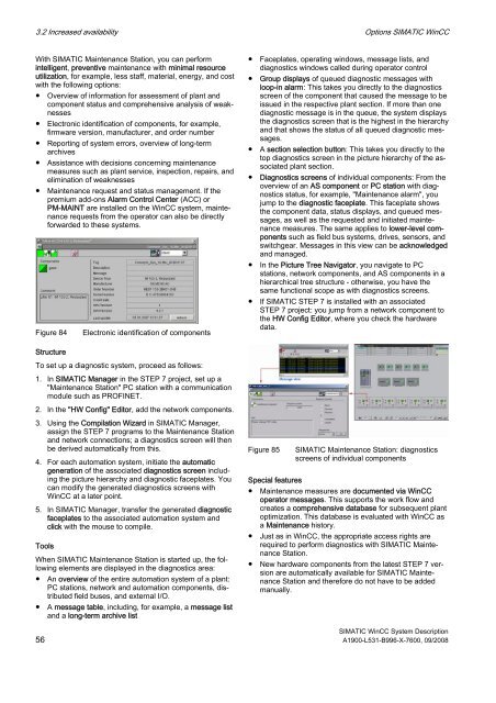
Figure 84 Electronic identification of components<br />
Structure<br />
To set up a diagnostic system, proceed as follows:<br />
1. In <strong>SIMATIC</strong> Manager in the STEP 7 project, set up a<br />
"Maintenance Station" PC station with a communication<br />
module such as PROFINET.<br />
2. In the "HW Config" Editor, add the network components.<br />
3. Using the Compilation Wizard in <strong>SIMATIC</strong> Manager,<br />
assign the STEP 7 programs to the Maintenance Station<br />
and network connections; a diagnostics screen will then<br />
be derived automatically from this.<br />
4. For each automation system, initiate the automatic<br />
generation of the associated diagnostics screen including<br />
the picture hierarchy and diagnostic faceplates. You<br />
can modify the generated diagnostics screens with<br />
<strong>WinCC</strong> at a later point.<br />
5. In <strong>SIMATIC</strong> Manager, transfer the generated diagnostic<br />
faceplates to the associated automation system and<br />
click with the mouse to compile.<br />
Tools<br />
When <strong>SIMATIC</strong> Maintenance Station is started up, the following<br />
elements are displayed in the diagnostics area:<br />
● An overview of the entire automation system of a plant:<br />
PC stations, network and automation components, distributed<br />
field buses, and external I/O.<br />
● A message table, including, for example, a message list<br />
and a long-term archive list<br />
● Faceplates, operating windows, message lists, and<br />
diagnostics windows called during operator control<br />
● Group displays of queued diagnostic messages with<br />
loop-in alarm: This takes you directly to the diagnostics<br />
screen of the component that caused the message to be<br />
issued in the respective plant section. If more than one<br />
diagnostic message is in the queue, the system displays<br />
the diagnostics screen that is the highest in the hierarchy<br />
and that shows the status of all queued diagnostic messages.<br />
● A section selection button: This takes you directly to the<br />
top diagnostics screen in the picture hierarchy of the associated<br />
plant section.<br />
● Diagnostics screens of individual components: From the<br />
overview of an AS component or PC station with diagnostics<br />
status, for example, "Maintenance alarm", you<br />
jump to the diagnostic faceplate. This faceplate shows<br />
the component data, status displays, and queued messages,<br />
as well as the requested and initiated maintenance<br />
measures. The same applies to lower-level components<br />
such as field bus systems, drives, sensors, and<br />
switchgear. Messages in this view can be acknowledged<br />
and managed.<br />
● In the Picture Tree Navigator, you navigate to PC<br />
stations, network components, and AS components in a<br />
hierarchical tree structure - otherwise, you have the<br />
same functional scope as with diagnostics screens.<br />
● If <strong>SIMATIC</strong> STEP 7 is installed with an associated<br />
STEP 7 project: you jump from a network component to<br />
the HW Config Editor, where you check the hardware<br />
data.<br />
Figure 85 <strong>SIMATIC</strong> Maintenance Station: diagnostics<br />
screens of individual components<br />
Special features<br />
● Maintenance measures are documented via <strong>WinCC</strong><br />
operator messages. This supports the work flow and<br />
creates a comprehensive database for subsequent plant<br />
optimization. This database is evaluated with <strong>WinCC</strong> as<br />
a Maintenance history.<br />
● Just as in <strong>WinCC</strong>, the appropriate access rights are<br />
required to perform diagnostics with <strong>SIMATIC</strong> Maintenance<br />
Station.<br />
● New hardware components from the latest STEP 7 version<br />
are automatically available for <strong>SIMATIC</strong> Maintenance<br />
Station and therefore do not have to be added<br />
manually.<br />
<strong>SIMATIC</strong> <strong>WinCC</strong> <strong>System</strong> <strong>Description</strong><br />
56 A1900-L531-B996-X-7600, 09/2008