Electronic signal transmitter - Bosch Rexroth
Electronic signal transmitter - Bosch Rexroth
Electronic signal transmitter - Bosch Rexroth

You also want an ePaper? Increase the reach of your titles
YUMPU automatically turns print PDFs into web optimized ePapers that Google loves.
<strong>Electronic</strong> <strong>signal</strong> <strong>transmitter</strong><br />
Type VT 10468<br />
Series 3X<br />
Single axis version<br />
Overview of contents<br />
Contents Page<br />
Features 1<br />
Ordering details 2<br />
Function 2<br />
Engineering guidelines 2<br />
Technical data 3<br />
Cable allocation 3<br />
Characteristic curves 3<br />
Zero position, directional and dead-man contact 4<br />
Switch in the lever 4<br />
Circuit example 5<br />
Unit dimensions 6<br />
Information on available spare parts:<br />
www.boschrexroth.com/spc<br />
Features<br />
RE 29753/04.05<br />
Replaces: 07.02<br />
F 87015_d<br />
1/6<br />
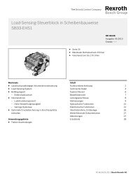
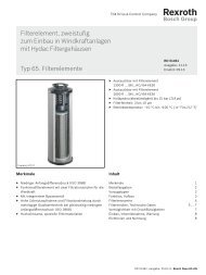
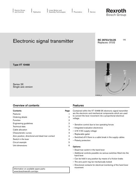
Contained within the VT 10468-3X electronic <strong>signal</strong> <strong>transmitter</strong><br />
are the electronic and mechanical components which are used<br />
to convert the lever movement into a proportional electrical<br />
voltage.<br />
– Sensitive control due to low operating forces<br />
– Integrated evaluation electronics<br />
– ±15 V DC supply voltage<br />
– Replacable gaiter<br />
– Switched off if there is a cable break in the supply cables<br />
– Polarity protection<br />
Options:<br />
– Dead-man switch in the hand lever<br />
– Additional controls possible via various switches fitted into the<br />
hand lever<br />
– Can be held in any position by means of a friction brake<br />
– The zero point may be mechanically locked<br />
– Directional contacts for electrical monitoring of the hand lever<br />
movement
2/6 <strong>Bosch</strong> <strong>Rexroth</strong> AG Hydraulics VT 10468 RE 29753/04.05<br />
Ordering details<br />
Single axis <strong>signal</strong> <strong>transmitter</strong><br />
Series 30 bis 39 = 3X<br />
(30 to 39: unchanged technical data and connection allocation)<br />
Additional functions<br />
Friction brake = B<br />
Spring return = F<br />
Lever form<br />
Hand lever<br />
Hand lever<br />
Hand lever<br />
Hand lever<br />
Hand lever<br />
Ball lever<br />
Ball lever<br />
Ball lever<br />
Function<br />
Additional functions<br />
None<br />
Push button<br />
Rocker switch<br />
Pressure operated switch<br />
Rocker switch with detent<br />
None<br />
With dead-man contact<br />
With mech. pull detent<br />
VT 10468 3X *<br />
Protection to EN 60529<br />
IP 65 = 0<br />
IP 65 = 1<br />
IP 65 = 2<br />
IP 65 = 3<br />
IP 65 = 4<br />
IP 65 = 5<br />
IP 53 = 6<br />
IP 65 = 7<br />
Mechanics<br />
The simple robust mechanism consists of a control lever mounted<br />
in a swivel bearing. By deflecting the lever, the setting of a<br />
plastic track potentiometer is changed. Dependent upon the<br />
model, the control lever is automatically spring returned to the<br />
neutral position or held in any position by a friction brake.<br />
A mechanical detent can also be fitted into the hand lever. The<br />
mechanism is protected by a rubber gaiter.<br />
Zero position, directional and dead-man contacts<br />
In order to be able to electrically monitor the direction of lever<br />
movement and the zero position, a switch can be fitted per<br />
half axis. This switch closes when the lever is moved between<br />
±5 % to ±10 % of the maximum travel (referred to the output<br />
<strong>signal</strong> of ±10 V).<br />
The transducer can also be fitted with a dead-man switch. This<br />
is operated by pressing the upper half of the hand lever (at<br />
right angles to the plane of installation).<br />
When these functions are required, they are connected via a<br />
2nd non-screened cable.<br />
Engineering guidelines<br />
Futher details in clear text<br />
Direction contact<br />
R0 = No contact<br />
RX = Contact in the X axis<br />
<strong>Electronic</strong>s<br />
The plastic track potentiometer is connected in series with an<br />
impedance converter, which ensures that the control curve remains<br />
within the specified limits, even with varying loading on<br />
the control output. The electronics also carry out other protective<br />
functions. Should a cable break in the ±15V lines occur,<br />
then the supply to the electronics is automatically switched off<br />
internally. The electrical connection is via multi-core screened<br />
cable.<br />
The combination of plastic track potentiometer and impedance<br />
converter ensures that a long service life is achieved.<br />
Attention: If the <strong>transmitter</strong> is installed in a fully isolated manner, then the <strong>transmitter</strong> housing must be earthed by a seperate<br />
cable!
RE 29753/04.05 VT 10468 Hydraulics <strong>Bosch</strong> <strong>Rexroth</strong> AG 3/6<br />
Technical data (for applications outside these parameters, please consult us!)<br />
<strong>Electronic</strong>s<br />
Supply voltage U ±15 VDC (± 1 %) stabilised<br />
Current consumption<br />
Control outputs<br />
I Approx. 30 mA<br />
– Output voltage U Max. ±10 V<br />
– Output current I Max. ±5 mA<br />
Switched contacts 2 A, Max. 30 VDC (ohmic load)<br />
Fuse<br />
Mechanics<br />
IS 2 A, medium blowing characteristics<br />
Lever displacement angle α Approx. 20° from the spring centre position to the end position<br />
(when operated in the X direction)<br />
Operating force<br />
Protection to EN 60529<br />
F Start value approx. 6 N<br />
Final value approx. 10 N<br />
– above the mounting plane: See ordering details<br />
– below the mounting plane: IP 65<br />
Cable length l 600 mm<br />
Permissible ambient temperature ϑ –25 to +70 °C<br />
Weight m Approx. 1.5 kg<br />
Cable allocation<br />
Colour of the connecting cables (cable 1 – screened):<br />
Supply lines: Red +15 V<br />
Black M0 (measured zero)<br />
Blue –15 V<br />
Signal lines: White M0 (measured zero)<br />
Pink X axis<br />
Screen: Yellow/green Housing <strong>transmitter</strong><br />
Transparent Screen<br />
Notes: – The cable screen is not connected internally!<br />
– If the <strong>transmitter</strong> is installed in a fully isolated<br />
manner, then the <strong>transmitter</strong> housing must be<br />
connected to earth!<br />
Colours of the connecting cables (cable 2 – non screened):<br />
Feed cable: Blue<br />
Directional contacts: Grey/Pink XA Red/Blue XB Dead-man contact: Grey<br />
Zero position contact: Black X axis<br />
Characteristic curves<br />
X axis<br />
≈ 20 °<br />
≈ 1 °<br />
X A + 10 V<br />
X B<br />
≈ 1 °<br />
– 10 V<br />
≈ 20 °<br />
Lever displacement angle
4/6 <strong>Bosch</strong> <strong>Rexroth</strong> AG Hydraulics VT 10468 RE 29753/04.05<br />
Zero position, directional and deadman contacts<br />
2 A<br />
Switch in the lever<br />
2 A<br />
2 A<br />
Directional contact X A<br />
Directional contact X B<br />
Dead-man contact<br />
Pressure switch and push button<br />
Violet White<br />
Rocker switch and rocker switch with detent<br />
Violet<br />
Colours of the connecting cable (cable 2 – non screened):<br />
Feed cable: Violet<br />
Pressure operated switch and push button: White<br />
Rocker switch and rocker switch with detent: Brown<br />
–<br />
–<br />
White<br />
Brown<br />
Zero position contact X axis
RE 29753/04.05 VT 10468 Hydraulics <strong>Bosch</strong> <strong>Rexroth</strong> AG 5/6<br />
Circuit example<br />
Supply<br />
voltage<br />
Supply<br />
voltage<br />
Supply<br />
voltage<br />
Switching<br />
amplifier<br />
VT 11005<br />
+ –<br />
12 V<br />
24 V<br />
Switched <strong>signal</strong><br />
output<br />
Proportionalamplifier<br />
VT 11006<br />
Power supply<br />
module<br />
Directional and<br />
zero position relays<br />
Proportional solenoids Switching solenoids
6/6 <strong>Bosch</strong> <strong>Rexroth</strong> AG Hydraulics VT 10468 RE 29753/04.05<br />
Unit dimensions (dimensions in mm)<br />
165<br />
11<br />
4<br />
65<br />
50<br />
20 °<br />
90<br />
105<br />
20 °<br />
80 55<br />
4 x Ø6,5<br />
XB XA –10V +10V<br />
<strong>Bosch</strong> <strong>Rexroth</strong> AG<br />
Hydraulics<br />
Zum Eisengießer 1<br />
97816 Lohr am Main, Germany<br />
Telefon +49 (0) 93 52 / 18-0<br />
Telefax +49 (0) 93 52 / 18-23 58<br />
documentation@boschrexroth.de<br />
www.boschrexroth.de<br />
5<br />
1<br />
3<br />
4<br />
Front<br />
Ø38<br />
7 2<br />
120<br />
Z<br />
Ø42<br />
1 Hand lever<br />
2 Ball lever<br />
3 Mounting face<br />
4 Connecting cables (length 600 mm)<br />
5 Switch in lever (see ordering details)<br />
6 Dead-man contact<br />
7 Pull detent<br />
© This document, as well as the data, specifi cations and other<br />
information set forth in it, are the exclusive property of <strong>Bosch</strong> <strong>Rexroth</strong><br />
AG. Without their consent it may not be reproduced or given to third<br />
parties.<br />
The data specifi ed above only serve to describe the product. No<br />
statements concerning a certain condition or suitability for a certain<br />
application can be derived from our information. The information given<br />
does not release the user from the obligation of own judgement and<br />
verifi cation. It must be remembered that our products are subject to a<br />
natural process of wear and aging.<br />
T<br />
6