Design of LCOS Microdisplay Backplanes for Projection Applications
Design of LCOS Microdisplay Backplanes for Projection Applications
Design of LCOS Microdisplay Backplanes for Projection Applications

Create successful ePaper yourself
Turn your PDF publications into a flip-book with our unique Google optimized e-Paper software.
Chapter 2: Constraints from lcos technology CH2 - 51<br />
Finally, with the placed spacer solution, the designer must produce a dedicated mask<br />
layout.<br />
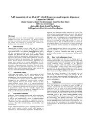
Figure 2-13 : placed spacer comets<br />
The second solution consists <strong>of</strong> spraying tiny spacer balls on top <strong>of</strong> the alignment<br />
layer. Their positions are random and differ from chip to chip. To its advantage, the<br />
second solution does not exhibit shadows or comets.<br />
Spacer thickness depends on the LC effect; the precision <strong>of</strong> the LC layer’s thickness<br />
also depends on the planarity <strong>of</strong> the Si chip. Note that the visibility <strong>of</strong> spacers can<br />
depend on the state <strong>of</strong> the LC director. It is important <strong>for</strong> good contrast ratios to have<br />
no spacer visibility in the dark state. On the other hand, when spacers are visible in<br />
the bright state, it will affect the brightness <strong>of</strong> the display.<br />
2.2.1.3 Chip planarity<br />
Some LC modes require extremely well controlled thickness <strong>of</strong> the LC layer. Others<br />
are more tolerant to thickness variations. Fact is, without precautions, a chip's<br />
surface topography presents 'hills' and 'dales' <strong>of</strong> the order <strong>of</strong> micrometer. This is not<br />
surprising, considering the thickness <strong>of</strong> the patterned layers (µm range). As the<br />
topography variations are large enough compared with the cell gap, it can be<br />
expected that the Si planarity affects the quality <strong>of</strong> the assembled cell.<br />
A first technique to smoothen the chip surface consists <strong>of</strong> the addition <strong>of</strong> a<br />
planarizing poly-imide layer just below the top mirror layer. Furthermore, this layer<br />
can be made opaque so that it results in an excellent light shield [23]. Fortunately,<br />
advanced sub micron processes already suffer this much from excessive surface<br />
topography that foundries anyway had to introduce a polishing technique known as<br />
chemical mechanical polishing (CMP), [59].The processing step consists <strong>of</strong> the<br />
deposition <strong>of</strong> an insulator layer that reduces the topography variations; next, this<br />
layer is polished to yield a very flat surface. The CMP step here comes after the<br />
patterning <strong>of</strong> a conductor layer (poly and/or metal layers) and covering it with an<br />
insulator. It is incapable to yield a mathematically flat surface; it works as an<br />
integrator that averages 'fast' topography variations over a small distance range. It<br />
cannot cancel topography variations that are too steep on short range or that slowly<br />
CH2 - 51