Epidemiological principles for EMF and EMR studies - Lincoln ...
Epidemiological principles for EMF and EMR studies - Lincoln ...
Epidemiological principles for EMF and EMR studies - Lincoln ...

You also want an ePaper? Increase the reach of your titles
YUMPU automatically turns print PDFs into web optimized ePapers that Google loves.
31<br />
where VERP = total peak visual ERP <strong>for</strong> NTSC TV stations, in kW,<br />
AERP = total aural (or average <strong>for</strong> DVD stations) ERP, in kW,<br />
RFF = relative field factor, vertical antenna pattern, at the direction to the<br />
actual point of calculation, <strong>and</strong><br />
D = Distance from the centre of radiation to the point of calculation, in m.<br />
The factor of 2.56 accounts <strong>for</strong> the increase in power density due to ground<br />
reflection. The factor of 1.64 is the gain of a halfway dipole relative to an isotropic<br />
radiator, part of the horizontal antenna pattern. The factor of 0.4 converts the peak<br />
visual ERP <strong>for</strong> TV stations to an average RMS value <strong>for</strong> FM radio stations <strong>and</strong> DTV<br />
(Digital TV) stations the value of the VERP is zero. This shows the vital importance<br />
of the relative field factor which deals with main beam <strong>and</strong> side lobes, Figures 16 to<br />
18.<br />
Around broadcast towers the ground level exposure patterns are a function of the<br />
power of the source signal <strong>and</strong> the antenna gain. The gain, expressed as a<br />
function of the Equivalent Isotropic Radiated Power (EIRP) is a function of the<br />
technology used to focus the signal. Antennae are complex elements that attempt<br />
to efficiently focus the main beam <strong>and</strong> minimize the side-lobes. The ability to do<br />
this to some extent is a function of the carrier frequency. Because of these sidelobes<br />
a complex antenna pattern is <strong>for</strong>med with undulating peaks in the 'near field'<br />
towers, which typically extends out to 5 to 6 km. VHF antenna patterns produce<br />
ground level Pattern A, with a high exposure peak within 1 km of the tower.<br />
Vertical Antenna Patterns:<br />
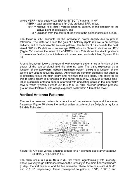
The vertical antenna pattern is a function of the antenna type <strong>and</strong> the carrier<br />
frequency. Figure 16 shows the vertical antenna pattern of an 8-dipole array <strong>for</strong> a<br />
98 MHz FM station.<br />
Figure 16: A typical vertical antenna pattern <strong>for</strong> a 4-element dipole array at about<br />
98 MHz.(VHF), Units in dB.<br />
The radial scale in Figure 16 is in dB that varies logarithmically with intensity.<br />
There is a very large difference between the intensity in the main horizontal beam<br />
(0 deg), the first minimum <strong>and</strong> the first side-lobe. These three points are -2.3, -28<br />
<strong>and</strong> -8.1 dB respectively. These correspond to gains of 0.588, 0.00016 <strong>and</strong>