
Create successful ePaper yourself
Turn your PDF publications into a flip-book with our unique Google optimized e-Paper software.
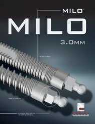
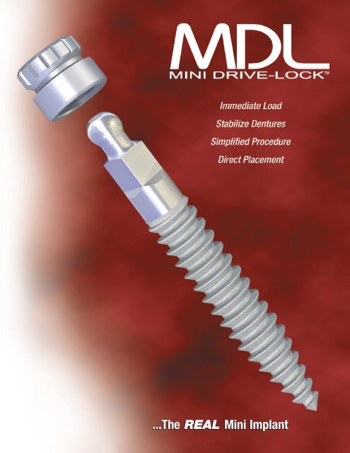
...The REAL Mini Implant
<strong>Intra</strong>-<strong>Lock</strong> <strong>MDL</strong> Mini Dental<br />
Implants (U.S. Patent 7,033,174)<br />
are progressively acid-etched and<br />
available in 2 diameters (2mm and<br />
2.5mm) and five lengths (10 mm,<br />
11.5 mm, 13 mm, 15 mm, 18 mm).<br />
<strong>MDL</strong> implants have an efficient<br />
self-tapping thread profile and a polished<br />
collar, just like a full-sized<br />
implant. The <strong>Intra</strong>-<strong>Lock</strong> ® <strong>MDL</strong> <br />
System includes an abutment<br />
designed for true provisional applications.<br />
A N D A N C I L L A R Y I T E M S<br />
<strong>MDL</strong>RD<br />
<strong>MDL</strong>CAD<br />
SRA<br />
DRILLS<br />
•<br />
•<br />
•<br />
•<br />
Polished Collar<br />
Self-Limiting Depth Design<br />
Profiled for Strength<br />
and Stability<br />
Optimum Thread Pitch<br />
and Surface Finish<br />
C O M P O N E N T S A N D<br />
<strong>MDL</strong>SPD<br />
<strong>MDL</strong>SPDL<br />
<strong>MDL</strong>RDL<br />
<strong>MDL</strong>2513L <strong>MDL</strong>2013<br />
<strong>MDL</strong>MW<br />
RPCA3<br />
Length<br />
Active Length<br />
Mini Drive-<strong>Lock</strong> IMPLANTS<br />
<strong>MDL</strong>2513<br />
•<br />
Sharp Apical Guiding Point<br />
*Active Length: Portion submerged in bone<br />
Mini Drive-<strong>Lock</strong> Pilot Twist Drill<br />
Ref No.<br />
• Single Patient 1.2mm diameter - Sterile..............................................<strong>MDL</strong>SPD<br />
• Single Patient 1.2mm diameter 13mm Long - Sterile ........................<strong>MDL</strong>SPDL<br />
IMPLANT INSERTION INSTRUMENTS<br />
Mini Drive-<strong>Lock</strong> Contra Angle Driver<br />
• Contra Angle Driver ........................................................................ <strong>MDL</strong>CAD<br />
Mini Drive-<strong>Lock</strong> Ratchet Drivers<br />
Use as an <strong>MDL</strong> Hand Driver or with a Surgical Ratchet Wrench<br />
• Mini Drive-<strong>Lock</strong> Ratchet Driver .......................................................... <strong>MDL</strong>RD<br />
• Mini Drive-<strong>Lock</strong> Ratchet Driver, Long .............................................. <strong>MDL</strong>RDL<br />
Mini Drive-<strong>Lock</strong> Manual Wrench<br />
• Connects to the Mini Drive-<strong>Lock</strong> Ratchet Driver .............................. <strong>MDL</strong>MW<br />
Surgical Ratchet Wrench<br />
• With standard 4 x 4mm connection, autoclavable .................................... SRA<br />
Tissue Punch<br />
• Latch Tissue Punch ø3mm .................................................................... RPCA3
All implants are packaged with the Micro Metal Housing with O-Ring.<br />
<strong>MDL</strong> Mini Drive-<strong>Lock</strong> implants, 2.0mm Diameter<br />
*Length 10mm 11.5mm 13mm 15mm 18mm<br />
Ref No. <strong>MDL</strong>2010 <strong>MDL</strong>2011 <strong>MDL</strong>2013 <strong>MDL</strong>2015 <strong>MDL</strong>2018<br />
<strong>MDL</strong> Mini Drive-<strong>Lock</strong> implants, 2.5mm Diameter<br />
*Length 10mm 11.5mm 13mm 15mm 18mm<br />
Ref No. <strong>MDL</strong>2510 <strong>MDL</strong>2511 <strong>MDL</strong>2513 <strong>MDL</strong>2515 <strong>MDL</strong>2518<br />
MICRO Metal Housing included.<br />
Length includes a 2mm gingival collar, therefore the amount submerged in bone is 2mm less than<br />
the referenced length of the implant.<br />
<strong>MDL</strong> Mini Drive-<strong>Lock</strong> implants, 2.5mm Diameter, Long Collar<br />
**Length 10mm 11.5mm 13mm 15mm 18mm<br />
Ref No. <strong>MDL</strong>2510L <strong>MDL</strong>2511L <strong>MDL</strong>2513L <strong>MDL</strong>2515L <strong>MDL</strong>2518L<br />
**Length includes a 4mm gingival collar, therefore the amount submerged in bone is 4mm less than<br />
the referenced length of the implant.<br />
PROSTHETIC COMPONENTS<br />
A N C I L L A R Y I T E M S<br />
Mini Drive-<strong>Lock</strong> Surgical Box<br />
Accommodates all <strong>MDL</strong>TM surgical instruments for <strong>MDL</strong>TM Implant Ref No.<br />
delivery and placement.<br />
• Laser etched Stainless steel insert ............................................................ <strong>MDL</strong>SK<br />
Mini Drive-<strong>Lock</strong> Laboratory Analog<br />
• Replicates the <strong>MDL</strong> Implant and abutment .............................................. <strong>MDL</strong>A<br />
Mini Drive-<strong>Lock</strong> Metal Housing with O-Ring<br />
• O-Ring encapsulated in MICRO metal housing .................................. <strong>MDL</strong>MMH<br />
• O-Ring encapsulated in LARGE metal housing ...................................... <strong>MDL</strong>MH<br />
<strong>MDL</strong> O-Ring Replacements<br />
• For MICRO Housing (Quantity of 10) .................................................. <strong>MDL</strong>MOR<br />
• For LARGE Housing (Quantity of 10) ...................................................... <strong>MDL</strong>OR<br />
Mini Drive-<strong>Lock</strong> Cement-Over Abutments<br />
• Cements over O-Ball assembly for temporary fixed bridges<br />
Straight .................................................................................................... <strong>MDL</strong>SA<br />
• Cements over O-Ball assembly for temporary fixed bridges<br />
Angulated 15°...................................................................................... <strong>MDL</strong>AA15<br />
• Plastic Castable Abutment for temporary fixed bridges ..............................<strong>MDL</strong>PA<br />
Mini Drive-<strong>Lock</strong> Impression Coping<br />
• Pick up impression Coping ........................................................................ <strong>MDL</strong>T<br />
<strong>MDL</strong>MH<br />
<strong>MDL</strong>OR<br />
<strong>MDL</strong> Implants have always had<br />
an integral polished collar to promote<br />
tissue health. Its profile and<br />
dimensions are all carefully calculated<br />
to provide maximum<br />
strength at the point where the<br />
highest insertion forces are generated.<br />
In addition, <strong>MDL</strong> <br />
Implant’s thread pitch and<br />
wedge profile permit intimate<br />
contact between the bone and<br />
implant surface ensuring initial<br />
stability and encouraging immediate<br />
load success.<br />
Predictable and efficient delivery<br />
and placement are achieved with<br />
Drive-<strong>Lock</strong> technology. <strong>MDL</strong> <br />
Implants can be removed from<br />
their sterile vial, transferred<br />
directly to the surgical site<br />
and are threaded into place all in<br />
one fluid, ergonomic motion.<br />
<strong>MDL</strong>MMH<br />
<strong>MDL</strong>A <strong>MDL</strong>SA <strong>MDL</strong>AA15<br />
<strong>MDL</strong>MOR<br />
<strong>MDL</strong>PA <strong>MDL</strong>T
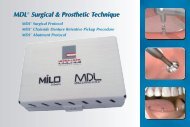
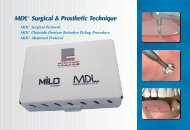
<strong>MDL</strong> <strong>MDL</strong> Surgical & Prosthetic Technique<br />
Surgical & Prosthetic Technique<br />
<strong>MDL</strong> Surgical Protocol<br />
<strong>MDL</strong> Chairside Denture Retentive Pickup Procedure<br />
<strong>MDL</strong> Temporary Abutment Protocol<br />
(Fig. 1) The <strong>MDL</strong> 1.2mm Pilot<br />
Drill breaches the gingival tissue.<br />
(Fig. 4) Using Drive-<strong>Lock</strong> <br />
Technology, an <strong>MDL</strong> Implant is<br />
removed from its sterile container.<br />
(Fig. 7) An <strong>MDL</strong> Ratchet Driver<br />
with a Ratchet Wrench is used.<br />
(Fig. 2) Copious sterile saline<br />
irrigation is recommended.<br />
(Fig. 5) <strong>MDL</strong> ’s sharp apical guiding<br />
point initiates self-tapping action.<br />
(Fig. 8) Small incremental turns takes<br />
advantage of bone’s viscoelastic nature.<br />
- 2 -<br />
(Fig. 3) Care is taken to breach<br />
the cortical plate.<br />
(Fig. 6) … threading and expanding<br />
the bone at the same time.<br />
(Fig. 9) Seating is accomplished<br />
when the Ratchet Driver is flush<br />
with the surrounding gingival tissue.
<strong>MDL</strong> Surgical Procedure<br />
Overdenture Stabilization<br />
The Mini Drive-<strong>Lock</strong> Surgical Kit organizes all instrumentation necessary for the procedure and features a<br />
convenient stainless-steel tray that is easily removed and placed in the sterile operator field.<br />
Light, repeated, intermediate, vertical introduction of the <strong>MDL</strong> 1.2mm Pilot Twist Drill breaches the gingival<br />
tissue and periosteum (Fig. 1). Copious sterile saline irrigation is recommended (Fig. 2). Drilling depth is<br />
approximately one third the length of the implant with care taken to breach the cortical plate (Fig. 3).<br />
<strong>MDL</strong> ’s are packaged suspended on titanium rings specially engineered to facilitate a no-touch delivery and<br />
placement utilizing Drive-<strong>Lock</strong> technology (Fig. 4). The <strong>MDL</strong> Contra-Angle Driver (<strong>MDL</strong>CAD) is engineered<br />
to slip over the O-ball assembly, firmly engaging the implant for direct delivery and initial seating.<br />
Use a slow speed high-torque handpiece (15 RPM or less) and the <strong>MDL</strong> Contra-Angle Driver to begin to insert<br />
the <strong>MDL</strong> Implant (Fig. 5). <strong>MDL</strong> ’s sharp apical guiding point initiates self-tapping action; threading and<br />
expanding the bone at the same time (Fig. 6). The use of an electric motor with a torque-limiting feature set to<br />
35Ncm is recommended.<br />
When the torque limiter stalls the handpiece an <strong>MDL</strong> Ratchet Driver<br />
(<strong>MDL</strong>RD) with a Surgical Ratchet Wrench (SRA) is used (Fig. 7). Small incremental<br />
turns; with a pause between each turn takes advantage of<br />
bone’s viscoelastic nature (Fig. 8).<br />
<strong>MDL</strong> Implant seating is accomplished when the Ratchet Driver is<br />
flush with the surrounding gingival tissue (Fig. 9).<br />
• • • • • • • • • • • • • • • • • • • • • • • • • • • • • • • • • • • • • • • • • • •<br />
(Fig. 1) A soft lead pencil marks the<br />
heads of the O-Balls.<br />
- 3 -<br />
(Fig. 2) An impression of the O-Balls is<br />
transferred to the denture.<br />
(Fig. 4) All openings are relieved. (Fig. 5) It is verified that the appliance is<br />
seated passively.<br />
(Fig. 7) All Retentive Housings are snapped<br />
into place.<br />
(Fig. 8) Appliance is seated passively in maximum<br />
intercuspation.<br />
- 4 -<br />
(Fig. 3) A resin bur relieves the opening.<br />
(Fig. 6) A Retentive Housing is snapped<br />
over the O-Ball.<br />
(Fig. 9) Holes are punched in a rubber dam<br />
at each implant site.
<strong>MDL</strong> Chairside Denture Retentive Pickup Procedure<br />
Overdenture Stabilization<br />
For chairside pickup of the <strong>MDL</strong> denture retentive component transfer the position of the O-Balls to the tissue-bearing<br />
surface of the denture by marking the heads of the O-Balls with a soft lead pencil (Fig. 1)<br />
or capturing their impression by inserting a strip of soft silicone or soft wax inside the denture. An impression<br />
is clearly visible on the tissue-bearing surface of the denture (Fig. 2).<br />
Using a resin bur, relieve the opening around the abutment impressions or markings in the denture<br />
(Fig. 3 & 4).<br />
Try the denture in the patient’s mouth and verify that the appliance is seated passively while in maximum<br />
intercuspation. The O-Balls should not touch any part of the denture. Have the patient close into maximum<br />
intercuspation and observe that the denture is stable and properly equilibrated at this point (Fig. 5).<br />
Snap a Retentive Housing Assembly over each O-Ball (Fig. 6 & 7). Try the denture in the patient’s mouth<br />
again and check to ensure that the appliance is seated passively while in maximum intercuspation (Fig. 8).<br />
Remove the Retentive Housings. Punch holes in a rubber dam at each implant site (Fig. 9).<br />
• • • • • • • • • • • • • • • • • • • • • • • • • • • • • • • • • • • • • • • • • • • • • • • • • • • •<br />
(Fig. 10) The rubber dam is placed over each<br />
abutment.<br />
(Fig. 13) The abutment recesses are filled with<br />
self cure resin.<br />
(Fig. 16) The patient closes into maximum<br />
intercuspation.<br />
- 5 -<br />
(Fig. 11) The O-Ball heads are left exposed<br />
and lubricated.<br />
(Fig. 14) This material is painted over each<br />
housing.<br />
(Fig. 17) The denture and the rubber dam is<br />
removed.<br />
- 6 -<br />
(Fig. 12) A Retentive Housing is snapped over<br />
each O-Ball.<br />
(Fig. 15) The denture is seated when the<br />
acrylic becomes resistant to flow.<br />
(Fig. 18) Flash is trimmed and any minor<br />
voids or discrepancies filled.
<strong>MDL</strong> Chairside Denture Retentive Pickup Procedure (Cont.)<br />
Overdenture Stabilization<br />
Place the rubber dam over each abutment, leaving only the O-Ball heads exposed. Lubricate the O-Ball heads<br />
(Fig. 10 & 11). These steps will prevent any acrylic lock-on.<br />
Snap a Retentive Housing Assembly over each O-Ball in preparation for final seating (Fig. 12).<br />
Clean, wash and dry the denture. Fill the abutment recesses with self cure resin (Fig. 13). Paint a small amount<br />
of this material over each retentive housing (Fig. 14). As soon as the acrylic in the denture becomes resistant to<br />
flow, seat the denture, keeping light, bilateral pressure on the occlusal surface (Fig. 15).<br />
While maintaining light bilateral pressure on the denture, have the patient close gently into maximum intercuspation<br />
(Fig. 16).<br />
Allow the acrylic to fully polymerize. After the acrylic has set, remove the denture and the<br />
rubber dam (Fig. 17). Trim flash and fill any minor voids or discrepancies. Ensure that<br />
there are no sharp edges on the tissue-bearing surface of the denture (Fig. 18).<br />
Recheck the occlusion. Confirm proper occlusal contacts.<br />
• • • • • • • • • • • • • • • • • • • • • • • • • • • • • • • • • • • • • • • • • • •<br />
<strong>MDL</strong> Temporary<br />
Abutment Protocol<br />
Increase your treatment solutions with<br />
<strong>Intra</strong>-<strong>Lock</strong> ® ’s <strong>MDL</strong> Cement-Over<br />
Abutments designed for true provisional<br />
applications. The abutment simply fits over<br />
the O-Ball Assembly and converts the<br />
implant from removable to fixed prosthetic<br />
options. <strong>MDL</strong> Abutments are available in<br />
straight and 15 degree angulated versions.<br />
Resin cement secures the abutment to the<br />
implant and temporary cement is used<br />
when placing the metal reinforced bridge<br />
on prepared abutments.<br />
Prior to the placement <strong>MDL</strong> implants, appropriate and<br />
adequate training in all phases of <strong>MDL</strong> Ω Implant procedures<br />
is strongly recommended. A comprehensive<br />
patient interview, medical/dental history and a complete<br />
oral examination should be conducted. Diagnostic radiographs<br />
and mounted study models, if appropriate,<br />
should also be obtained.<br />
<strong>Intra</strong>-<strong>Lock</strong> ® is a registered trademark of <strong>Intra</strong>-<strong>Lock</strong><br />
International, Inc. <strong>MDL</strong> Mini Drive-<strong>Lock</strong> is a trademark<br />
of <strong>Intra</strong>-<strong>Lock</strong> International, Inc. U.S. Patent 7,033,174<br />
and other U.S. & Foreign Patents Pending.<br />
www.intra-lock.com • info@intra-lock.com<br />
- 7 -<br />
(Fig. 1) <strong>MDL</strong> Implant is surgically<br />
placed in to position.<br />
(Fig. 4) Loaded tray is placed<br />
for the appropriate amount<br />
of time.<br />
(Fig. 7) Working model is<br />
poured.<br />
- 8 -<br />
(Fig. 2) <strong>MDL</strong> Impression<br />
Coping (<strong>MDL</strong>T) slides over the<br />
O-Ball Abutment.<br />
(Fig. 5) Coping is firmly<br />
picked up in the impression.<br />
(Fig. 8) Appropriate <strong>MDL</strong> Abutment<br />
is prepared and cemented over the<br />
O-Ball with resin cement.<br />
(Fig. 3) Pre-formed custom tray<br />
is loaded with a monophase<br />
impression material.<br />
(Fig. 6) <strong>MDL</strong> Laboratory<br />
Analog (<strong>MDL</strong>A) is Inserted into<br />
the Impression Coping.<br />
(Fig. 9) Restoration is cemented<br />
into place after proper esthetics<br />
and occlusion are confirmed.
GLOBAL HEADQUARTERS<br />
1200 N. Federal Highway, 209<br />
Boca Raton, FL 33432 USA<br />
Tel: 877-330-0338<br />
www.intra-lock.com • info@intra-lock.com<br />
Prior to the placement <strong>MDL</strong> implants, appropriate and adequate training in all phases of<br />
<strong>MDL</strong> Ω Implant procedures is strongly recommended. A comprehensive patient interview, medical/dental<br />
history and a complete oral examination should be conducted. Diagnostic radiographs<br />
and mounted study models, if appropriate, should also be obtained.<br />
<strong>Intra</strong>-<strong>Lock</strong> ® is a registered trademark of <strong>Intra</strong>-<strong>Lock</strong> International, Inc.<br />
<strong>MDL</strong> Mini Drive-<strong>Lock</strong> is a trademark of <strong>Intra</strong>-<strong>Lock</strong> International, Inc.<br />
U.S. Patent 7,033,174 and other U.S. & Foreign Patents Pending.<br />
0499 • EUROPE: INTRA-LOCK INTERNATIONAL, INC., • © COPYRIGHT 2006, INTRA-LOCK ® CE<br />
SYSTEM INTERNATIONAL • S4EN-06-04