THE WORLD OF TIMING BELTS - MAELabs UCSD
THE WORLD OF TIMING BELTS - MAELabs UCSD
THE WORLD OF TIMING BELTS - MAELabs UCSD

You also want an ePaper? Increase the reach of your titles
YUMPU automatically turns print PDFs into web optimized ePapers that Google loves.
overloaded which may cause an edge<br />
cord failure that propagates across the<br />
entire belt width. Angular misalignment<br />
often results in high belt-tracking forces<br />
as well which cause accelerated belt<br />
edge wear, sometimes leading to flange<br />
failure or belts tracking off of the pulleys.<br />
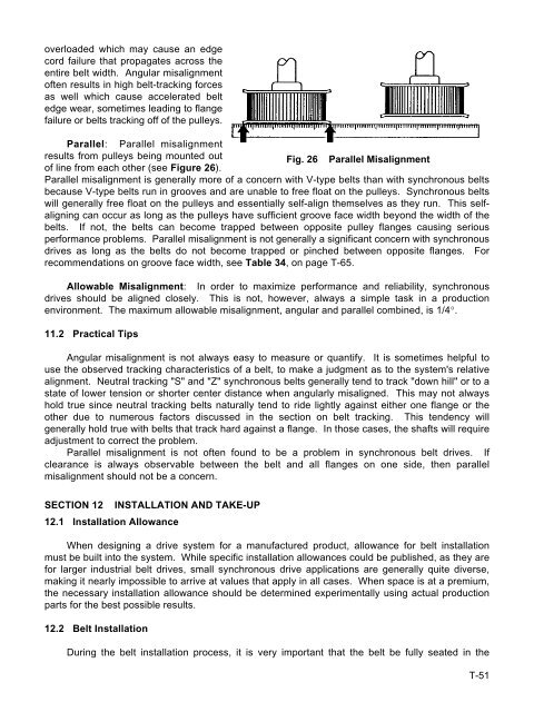
Parallel: Parallel misalignment<br />
results from pulleys being mounted out<br />
Fig. 26 Parallel Misalignment<br />
of line from each other (see Figure 26).<br />
Parallel misalignment is generally more of a concern with V-type belts than with synchronous belts<br />
because V-type belts run in grooves and are unable to free float on the pulleys. Synchronous belts<br />
will generally free float on the pulleys and essentially self-align themselves as they run. This selfaligning<br />
can occur as long as the pulleys have sufficient groove face width beyond the width of the<br />
belts. If not, the belts can become trapped between opposite pulley flanges causing serious<br />
performance problems. Parallel misalignment is not generally a significant concern with synchronous<br />
drives as long as the belts do not become trapped or pinched between opposite flanges. For<br />
recommendations on groove face width, see Table 34, on page T-65.<br />
Allowable Misalignment: In order to maximize performance and reliability, synchronous<br />
drives should be aligned closely. This is not, however, always a simple task in a production<br />
environment. The maximum allowable misalignment, angular and parallel combined, is 1/4°.<br />
11.2 Practical Tips<br />
Angular misalignment is not always easy to measure or quantify. It is sometimes helpful to<br />
use the observed tracking characteristics of a belt, to make a judgment as to the system's relative<br />
alignment. Neutral tracking "S" and "Z" synchronous belts generally tend to track "down hill" or to a<br />
state of lower tension or shorter center distance when angularly misaligned. This may not always<br />
hold true since neutral tracking belts naturally tend to ride lightly against either one flange or the<br />
other due to numerous factors discussed in the section on belt tracking. This tendency will<br />
generally hold true with belts that track hard against a flange. In those cases, the shafts will require<br />
adjustment to correct the problem.<br />
Parallel misalignment is not often found to be a problem in synchronous belt drives. If<br />
clearance is always observable between the belt and all flanges on one side, then parallel<br />
misalignment should not be a concern.<br />
SECTION 12 INSTALLATION AND TAKE-UP<br />
12.1 Installation Allowance<br />
When designing a drive system for a manufactured product, allowance for belt installation<br />
must be built into the system. While specific installation allowances could be published, as they are<br />
for larger industrial belt drives, small synchronous drive applications are generally quite diverse,<br />
making it nearly impossible to arrive at values that apply in all cases. When space is at a premium,<br />
the necessary installation allowance should be determined experimentally using actual production<br />
parts for the best possible results.<br />
12.2 Belt Installation<br />
During the belt installation process, it is very important that the belt be fully seated in the<br />
T-51