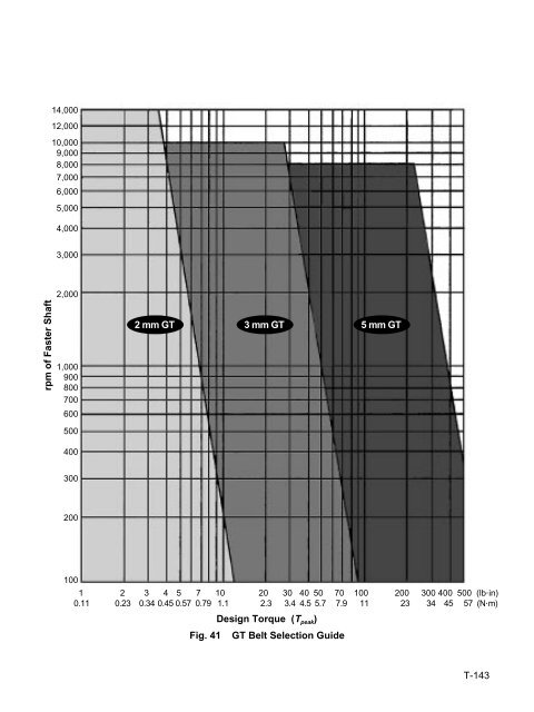
SECTION 24 <strong>TIMING</strong> BELT DRIVE SELECTION PROCEDURE Step 1 Determination of design load Drives consist of a driver and a driven pulley. In general, both pulleys are not of the same size; therefore, a speed reduction or increase occurs. Both convey the same power; however, the torque on each pulley is different. Drive designs should be based on the smaller pulley which will be subject to higher speed. The peak design load must be taken into account, and it is obtained by multiplying the torque by a service factor. Service factors between 1.5 and 2.0 are generally recommended when designing small pitch synchronous drives. Knowledge of drive loading characteristics should influence the actual value selected. A higher service factor should be selected for applications with high peak loads, high operating speeds, unusually severe operating conditions, etc. Lower service factors can be used when the loading is smooth, well defined, etc. and the reliability is less critical. Some designs may require service factors outside the 1.5 to 2.0 range, depending upon the nature of the application. If a stall torque of the driver is not given but the nameplate horsepower or kW power consumption is known, the torque can be obtained from: 63.025 x Shaft HP T (lb•in) = ––––––––––––––––– (24-1) Shaft rpm T (lb•in) = 8.85 x T (N•m) or (24-2) T (oz•in) = 16 x T (lb•in) (24-3) Tpeak = T x Service Factor (24-4) 1 kW = 1.341 HP (24-5) Step 2 Choice of belt pitch As shown in Figure 4, (page T-6) different belt pitches can satisfy the same horsepower requirements, also taking into account the speed of the faster shaft. The choice is somewhat individual and may take into account, among others, the following factors: • compatibility with previous designs • superiority of GT drives as far as noise, backlash, positioning accuracy, etc. is concerned • local availability for replacement • size limitations; i.e. the size of pulleys and of the entire drive will be optimized if GT or HTD pitches are used Step 3 Check belt pitch selection based on individual graphs Graphs shown on Figures 41 through 43 show the peak torque, Tpeak computed previously, plotted against the speed of faster shaft. Since the belt pitch was chosen in Step 2, reference to these graphs will confirm the validity of the selection. As an example, assume that the following data was obtained: Tpeak = 0.5 N•m and 1000 rpm. The potential choices are: 2 mm GT, 3 mm HTD, or XL. The 2 mm drive will be substantially smaller than the other choices. Step 4 Determine speed ratio Use CD-ROM or Drive Ratio Tables shown in SECTION 21, starting at page T-68, and establish the number of teeth of the small and large pulley based on the chosen speed ratio. Attempt to use available stock sizes for best economy. Use of the CD-ROM will immediately guide you to the appropriate catalog page and part number. Make note of the Pitch Diameter (PD) of the small pulley. T-142
pm of Faster Shaft 14,000 12,000 10,000 9,000 8,000 7,000 6,000 5,000 4,000 3,000 2,000 1,000 900 800 700 600 500 400 300 200 100 2 mm GT 3 mm GT 5 mm GT 1 2 3 4 5 7 10 20 30 40 50 70 100 200 300 400 500 (lb⋅in) 0.11 0.23 0.34 0.45 0.57 0.79 1.1 2.3 3.4 4.5 5.7 7.9 11 23 34 45 57 (N⋅m) Design Torque (T peak) Fig. 41 GT Belt Selection Guide T-143