THE WORLD OF TIMING BELTS - MAELabs UCSD
THE WORLD OF TIMING BELTS - MAELabs UCSD
THE WORLD OF TIMING BELTS - MAELabs UCSD

Create successful ePaper yourself
Turn your PDF publications into a flip-book with our unique Google optimized e-Paper software.
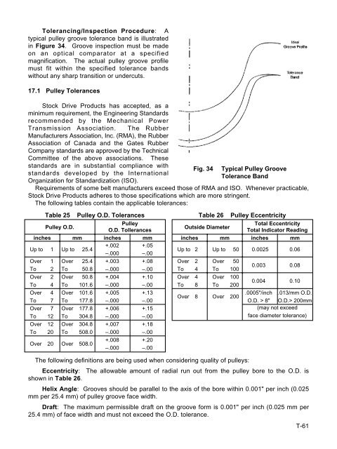
Tolerancing/Inspection Procedure: A<br />
typical pulley groove tolerance band is illustrated<br />
in Figure 34. Groove inspection must be made<br />
on an optical comparator at a specified<br />
magnification. The actual pulley groove profile<br />
must fit within the specified tolerance bands<br />
without any sharp transition or undercuts.<br />
17.1 Pulley Tolerances<br />
Stock Drive Products has accepted, as a<br />
minimum requirement, the Engineering Standards<br />
recommended by the Mechanical Power<br />
Transmission Association. The Rubber<br />
Manufacturers Association, Inc. (RMA), the Rubber<br />
Association of Canada and the Gates Rubber<br />
Company standards are approved by the Technical<br />
Committee of the above associations. These<br />
standards are in substantial compliance with<br />
standards developed by the International<br />
Organization for Standardization (ISO).<br />
Fig. 34 Typical Pulley Groove<br />
Tolerance Band<br />
Requirements of some belt manufacturers exceed those of RMA and ISO. Whenever practicable,<br />
Stock Drive Products adheres to those specifications which are more stringent.<br />
The following tables contain the applicable tolerances:<br />
Table 25 Pulley O.D. Tolerances<br />
Pulley O.D.<br />
Pulley<br />
O.D. Tollerances<br />
inches mm inches mm<br />
Up to 1 Up to 25.4<br />
+.002<br />
–.000<br />
+.05<br />
–.00<br />
Over 1 Over 25.4 +.003 +.08<br />
To 2 To 50.8 –.000 –.00<br />
Over 2 Over 50.8 +.004 +.10<br />
To 4 To 101.6 –.000 –.00<br />
Over 4 Over 101.6 +.005 +.13<br />
To 7 To 177.8 –.000 –.00<br />
Over 7 Over 177.8 +.006 +.15<br />
To 12 To 304.8 –.000 –.00<br />
Over 12 Over 304.8 +.007 +.18<br />
To 20 To 508.0 –.000 –.00<br />
Over 20 Over 508.0<br />
+.008<br />
–.000<br />
+.20<br />
–.00<br />
Table 26 Pulley Eccentricity<br />
Outside Diameter<br />
Total Eccentricity<br />
Total Indicator Reading<br />
inches mm inches mm<br />
Up to 2<br />
Over 2<br />
To 4<br />
Over 4<br />
To 8<br />
Over 8<br />
Up to 50<br />
Over 50<br />
To 100<br />
Over 100<br />
To 200<br />
Over 200<br />
0.0025<br />
0.003<br />
0.004<br />
0.06<br />
0.08<br />
0.10<br />
.0005"/inch .013/mm O.D.<br />
O.D. > 8" O.D.> 200mm<br />
(may not exceed<br />
face diameter tolerance)<br />
The following definitions are being used when considering quality of pulleys:<br />
Eccentricity: The allowable amount of radial run out from the pulley bore to the O.D. is<br />
shown in Table 26.<br />
Helix Angle: Grooves should be parallel to the axis of the bore within 0.001" per inch (0.025<br />
mm per 25.4 mm) of pulley groove face width.<br />
Draft: The maximum permissible draft on the groove form is 0.001" per inch (0.025 mm per<br />
25.4 mm) of face width and must not exceed the O.D. tolerance.<br />
T-61