THE WORLD OF TIMING BELTS - MAELabs UCSD
THE WORLD OF TIMING BELTS - MAELabs UCSD
THE WORLD OF TIMING BELTS - MAELabs UCSD

Create successful ePaper yourself
Turn your PDF publications into a flip-book with our unique Google optimized e-Paper software.
When identifying a shaft center location, each X-Y coordinate is specified with a measurement<br />
in the "X" as well as the "Y" direction. This requires a horizontal and vertical measurement for each<br />
shaft center in order to establish a complete coordinate. Either English or Metric units of measurement<br />
may be used.<br />
A complete coordinate is specified as follows:<br />
(X, Y) (13-1)<br />
where: X = measurement along X-axis (horizontal)<br />
Y = measurement along Y-axis (vertical)<br />
In specifying X and Y coordinates for each shaft center, the origin (zero point) must first be<br />
chosen as a reference. The driver shaft most often serves this purpose, but any shaft center can<br />
be used. Measurements for all remaining shaft centers must be taken from this origin or reference<br />
point. The origin is specified as (0, 0).<br />
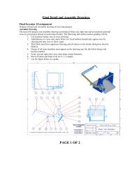
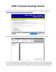
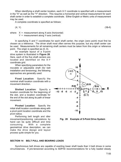
An example layout of a 5-point<br />
drive system is illustrated in Figure 28.<br />
Here, each of the five shaft centers are<br />
located and identified on the X-Y<br />
coordinate grid.<br />
When specifying parameters for the<br />
movable or adjustable shaft (for belt<br />
installation and tensioning), the following<br />
approaches are generally used:<br />
Fixed Location: Specify the<br />
nominal shaft location coordinate with a<br />
movement direction.<br />
Slotted Location: Specify a<br />
location coordinate for the beginning of<br />
the slot, and a location coordinate for<br />
the end of the slot along its path of linear<br />
movement.<br />
Pivoted Location: Specify the<br />
initial shaft location coordinate along with<br />
a pivot point location coordinate and the<br />
pivot radius.<br />
Performing belt length and idler<br />
movement/positioning calculations by<br />
hand can be quite difficult and time<br />
consuming. With a complete<br />
geometrical drive description, we can<br />
make the drive design and layout<br />
process quite simple for you.<br />
SECTION 14 BELT PULL AND BEARING LOADS<br />
Fig. 28 Example of 5-Point Drive System<br />
Synchronous belt drives are capable of exerting lower shaft loads than V-belt drives in some<br />
circumstances. If pre-tensioned according to SDP/SI recommendations for a fully loaded steady<br />
T-55