Selenio SEL-MDX1 MPEG-2 Transport Stream ... - Biznine.com
Selenio SEL-MDX1 MPEG-2 Transport Stream ... - Biznine.com
Selenio SEL-MDX1 MPEG-2 Transport Stream ... - Biznine.com

You also want an ePaper? Increase the reach of your titles
YUMPU automatically turns print PDFs into web optimized ePapers that Google loves.
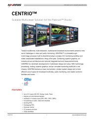
<strong>MDX1</strong><br />
<strong>MPEG</strong>-2 <strong>Transport</strong> <strong>Stream</strong><br />
Multiplexer/Demultiplexer<br />
Installation and Operation Manual<br />
D<br />
F<br />
Edition A<br />
175-100267-00
<strong>SEL</strong>-<strong>MDX1</strong><br />
<strong>MPEG</strong>-2 <strong>Transport</strong> <strong>Stream</strong><br />
Multiplexer/Demultiplexer<br />
Installation and Operation Manual<br />
Edition A<br />
March 2011
Harris Corporation<br />
Broadcast<br />
Communications<br />
Division<br />
4393 Digital Way<br />
Mason, OH USA<br />
45040<br />
Copyright © 2011, Harris Corporation, 1025 West NASA Boulevard, Melbourne, Florida 32919-0001 U.S.A. All<br />
rights reserved. This publication supersedes all previous releases. No part of this documentation may be reproduced<br />
in any form or by any means or used to make any derivative work without permission from Harris Corporation.<br />
Harris Corporation reserves the right to revise this documentation and to make changes in content from time to<br />
time without obligation on the part of Harris Corporation to provide notification of such revision or change.<br />
UNITED STATES GOVERNMENT LEGEND If you are a United States government agency, then this<br />
documentation and the software described herein are provided to you subject to the following:<br />
All technical data and <strong>com</strong>puter software are <strong>com</strong>mercial in nature and developed solely at private expense.<br />
Software is delivered as “Commercial Computer Software” as defined in DFARS 252.227-7014 (June 1995) or as a<br />
“<strong>com</strong>mercial item” as defined in FAR 2.101(a) and as such is provided with only such rights as are provided by<br />
Harris’ standard <strong>com</strong>mercial license for the Software. Technical data is provided with limited rights only as provided<br />
in DFAR 252.227-7015 (Nov 1995) or FAR 52.227-14 (June 1987), whichever is applicable. You agree not to<br />
remove or deface any portion of any legend provided on any licensed program or documentation contained in, or<br />
delivered to you in conjunction with, this User Guide.<br />
This publication, or any part thereof, may not be reproduced in any form, by any method, for any purpose, without<br />
the written consent of Harris Corporation.<br />
Contact Harris Corporation for permission to use materials as well as guidelines concerning foreign language<br />
translation and publication.<br />
Harris Corporation reserves the right to revise and improve its products as it chooses. This publication is designed<br />
to assist in the use of the product, as it exists on the date of publication of this manual, and may not reflect the<br />
product at the current time or an unknown time in the future. This publication does not in any way warrant<br />
description accuracy or guarantee the use for the product to which it refers.<br />
The Harris logo and assured <strong>com</strong>munications are registered trademarks of Harris Corporation. D-Series is a<br />
trademark of Harris Corporation. All other trademarks are held by their respective owners.<br />
This user guide was created for the <strong>Selenio</strong> <strong>SEL</strong>-<strong>MDX1</strong>, Edition A.<br />
Windows is a registered trademark of Microsoft Corporation. AMD and Operton are trademarks of Advanced<br />
Micro Devices, Inc. Dolby and the double-D symbol are registered trademarks of Dolby Laboratories. Java is a<br />
trademark of Sun Microsystems, Inc. or its subsidiaries in the United States and other countries.<br />
All other trademarks are the property of their respective holders.<br />
Publication Date: March 2011
Contents<br />
Preface..........................................................................................................................v<br />
Manual Information .......................................................................................................v<br />
Purpose ......................................................................................................................v<br />
Audience ....................................................................................................................v<br />
Revision History ..........................................................................................................v<br />
Writing Conventions ...................................................................................................v<br />
Obtaining Documents ................................................................................................vi<br />
Unpacking/Shipping Information ................................................................................vi<br />
Unpacking a Product .................................................................................................vi<br />
Product Servicing .......................................................................................................vi<br />
Returning a Product ...................................................................................................vi<br />
Safety Standards and Compliances ............................................................................ vii<br />
Restriction on Hazardous Substances (RoHS) Compliance .......................................... vii<br />
Waste from Electrical and Electronic Equipment (WEEE) Compliance ......................... vii<br />
Safety Terms and Symbols in this Manual ................................................................ viii<br />
Installation, Operation, and Specifications............................................. 1<br />
Overview ....................................................................................................................... 1<br />
Main Features ................................................................................................................ 1<br />
Front Module ................................................................................................................. 3<br />
Back Modules ................................................................................................................ 4<br />
Modules and Options ................................................................................................... 5<br />
Signal Flow .................................................................................................................... 6<br />
Installing <strong>MDX1</strong> Modules ............................................................................................. 7<br />
Removing <strong>Selenio</strong> Modules .......................................................................................... 8<br />
Front Module ............................................................................................................ 8<br />
Back Module ............................................................................................................. 8<br />
Powering Up a Module ................................................................................................. 9<br />
Upgrading Module Firmware ....................................................................................... 9<br />
Upgrade Failure Instructions ...................................................................................... 9<br />
Parameter Descriptions .............................................................................................. 10<br />
Module Name Block .................................................................................................... 10<br />
Name ...................................................................................................................... 10<br />
Function Map .............................................................................................................. 10<br />
Type ........................................................................................................................ 10<br />
Demux PID Map .......................................................................................................... 11<br />
IP LANs ......................................................................................................................... 11<br />
Primary and Secondary Data IP LANs ........................................................................ 11<br />
Time to Live ............................................................................................................. 12<br />
Primary and Secondary Data Eth MAC ..................................................................... 12<br />
Data Eth Protection ................................................................................................. 12<br />
iii<br />
Copyright © 2011, Harris Corporation
iv<br />
<strong>SEL</strong>-<strong>MDX1</strong><br />
Installation and Operation Manual<br />
Copyright © 2011, Harris Corporation<br />
Selected Data Eth Interface ......................................................................................12<br />
Multiplexers .................................................................................................................13<br />
Input Channels ........................................................................................................14<br />
DVBT Transmitter .....................................................................................................16<br />
General ....................................................................................................................16<br />
................................................................................................................................19<br />
IP Destinations .........................................................................................................19<br />
DVB .........................................................................................................................19<br />
DVBT .......................................................................................................................20<br />
Output TS Status ......................................................................................................20<br />
Output IP Status .......................................................................................................20<br />
Carousel Status ........................................................................................................20<br />
Demultiplexers ............................................................................................................21<br />
General ....................................................................................................................21<br />
IP Source ..................................................................................................................22<br />
Input TS Status .........................................................................................................22<br />
Input IP Status ..........................................................................................................23<br />
Output Channels .....................................................................................................23<br />
FEC ..........................................................................................................................24<br />
Demultiplexer PID Map ............................................................................................25<br />
Conditional Access System .........................................................................................25<br />
Vendor and CA Systems ID ......................................................................................25<br />
ECMG ......................................................................................................................26<br />
EMMG .....................................................................................................................26<br />
Access Criteria .........................................................................................................26<br />
Conditional Access SCG 1-240 ....................................................................................27<br />
Multiplexer ..............................................................................................................27<br />
Crypto Period ...........................................................................................................27<br />
ECM ........................................................................................................................27<br />
Reference Clock ...........................................................................................................28<br />
Specifications ...............................................................................................................29<br />
ASI Input and Output Specifications .........................................................................29<br />
SMPTE 310M Input and Output Specifications .........................................................30<br />
Reference Clock ...........................................................................................................30<br />
Index ...........................................................................................................................31
Preface<br />
Manual Information<br />
Purpose This manual details the features, installation, operation, maintenance, and specifications for<br />
the <strong>Selenio</strong> <strong>SEL</strong>-<strong>MDX1</strong> <strong>MPEG</strong>-2 <strong>Transport</strong> <strong>Stream</strong> Multiplexer/Demultiplexer.<br />
Audience This manual is written for engineers, technicians, and operators responsible for installation,<br />
setup, maintenance, and/or operation of the <strong>Selenio</strong> <strong>SEL</strong>-<strong>MDX1</strong> <strong>MPEG</strong>-2 <strong>Transport</strong> <strong>Stream</strong><br />
Multiplexer/Demultiplexer.<br />
Revision<br />
History<br />
Writing<br />
Conventions<br />
Table 2-1 Revision History of Manual<br />
Edition Date Comments<br />
A March 2011 Initial release<br />
To enhance your understanding, the authors of this manual have adhered to the following<br />
text conventions:<br />
Table 2-2 Writing Conventions<br />
Term or<br />
Convention<br />
Description<br />
Bold Indicates dialog boxes, property sheets, fields, buttons, check boxes,<br />
list boxes, <strong>com</strong>bo boxes, menus, submenus, windows, lists, and<br />
selection names<br />
Italics Indicates E-mail addresses, the names of books or publications, and<br />
the first instances of new terms and specialized words that need<br />
emphasis<br />
CAPS Indicates a specific key on the keyboard, such as ENTER, TAB, CTRL,<br />
ALT, or DELETE<br />
Code Indicates variables or <strong>com</strong>mand-line entries, such as a DOS entry or<br />
something you type into a field<br />
> Indicates the direction of navigation through a hierarchy of menus and<br />
windows<br />
Copyright © 2011, Harris Corporation<br />
v
vi<br />
<strong>SEL</strong>-<strong>MDX1</strong><br />
Installation and Operation Manual<br />
Obtaining<br />
Documents<br />
Copyright © 2011, Harris Corporation<br />
Product support documents can be viewed or downloaded from our website. Alternatively,<br />
contact your Customer Service representative to request a document.<br />
Unpacking/Shipping Information<br />
Unpacking a<br />
Product<br />
Product<br />
Servicing<br />
Returning a<br />
Product<br />
Table 2-2 Writing Conventions<br />
Term or<br />
Convention<br />
hyperlink Indicates a jump to another location within the electronic document<br />
or elsewhere<br />
Internet address Indicates a jump to a website or URL<br />
NOTE:<br />
Description<br />
Indicates important information that helps to avoid and troubleshoot<br />
problems<br />
This product was carefully inspected, tested, and calibrated before shipment to ensure years<br />
of stable and trouble-free service.<br />
1 Check equipment for any visible damage that may have occurred during transit.<br />
2 Confirm that you have received all items listed on the packing list.<br />
3 Contact your dealer if any item on the packing list is missing.<br />
4 Contact the carrier if any item is damaged.<br />
5 Remove all packaging material from the product and its associated <strong>com</strong>ponents before you<br />
install the unit.<br />
Keep at least one set of original packaging, in the event that you need to return a product<br />
for servicing.<br />
Except for firmware upgrades, <strong>SEL</strong>-<strong>MDX1</strong> modules are not designed for field servicing. All<br />
hardware upgrades, modifications, or repairs require you to return the modules to the<br />
Customer Service center.<br />
In the unlikely event that your product fails to operate properly, please contact Customer<br />
Service to obtain a Return Authorization (RA) number, and then send the unit back for<br />
servicing.<br />
Keep at least one set of original packaging in the event that a product needs to be returned<br />
for service. If the original package is not available, you can supply your own packaging as<br />
long as it meets the following criteria:<br />
The packaging must be able to withstand the product’s weight.<br />
The product must be held rigid within the packaging.<br />
There must be at least 2 in. (5 cm) of space between the product and the container.<br />
The corners of the product must be protected.
<strong>SEL</strong>-<strong>MDX1</strong><br />
Installation and Operation Manual<br />
Ship products back to us for servicing prepaid and, if possible, in the original packaging<br />
material. If the product is still within the warranty period, we will return the product prepaid<br />
after servicing.<br />
Safety Standards and Compliances<br />
The <strong>Selenio</strong> series safety manual is shipped in the Harris Infrastructure and Networking<br />
Documentation and Product Resources DVD, and can be downloaded from our website.<br />
Restriction on Hazardous Substances (RoHS) Compliance<br />
Directive 2002/95/EC—<strong>com</strong>monly known as the European Union (EU) Restriction on<br />
Hazardous Substances (RoHS)—sets limits on the use of certain substances found in<br />
electrical and electronic equipment. The intent of this legislation is to reduce the amount of<br />
hazardous chemicals that may leach out of landfill sites or otherwise contaminate the<br />
environment during end-of-life recycling. The Directive, which took effect on July 1, 2006,<br />
refers to the following hazardous substances:<br />
Lead (Pb)<br />
Mercury (Hg)<br />
Cadmium (Cd)<br />
Hexavalent Chromium (Cr-V1)<br />
Polybrominated Biphenyls (PBB)<br />
Polybrominated Diphenyl Ethers (PBDE)<br />
According to this EU Directive, all products sold in the European Union will be fully<br />
RoHS-<strong>com</strong>pliant and “lead-free.” (See our website for more information on dates and<br />
deadlines for <strong>com</strong>pliance.) Spare parts supplied for the repair and upgrade of equipment<br />
sold before July 1, 2006 are exempt from the legislation. Equipment that <strong>com</strong>plies with the<br />
EU directive will be marked with a RoHS-<strong>com</strong>pliant emblem, as shown in Figure 1.<br />
Figure P-1 RoHS Compliance Emblem<br />
Waste from Electrical and Electronic Equipment (WEEE) Compliance<br />
The European Union (EU) Directive 2002/96/EC on Waste from Electrical and Electronic<br />
Equipment (WEEE) deals with the collection, treatment, recovery, and recycling of electrical<br />
and electronic waste products. The objective of the WEEE Directive is to assign the<br />
responsibility for the disposal of associated hazardous waste to either the producers or users<br />
of these products. As of August 13, 2005, the producers or users of these products were<br />
required to recycle electrical and electronic equipment at end of its useful life, and may not<br />
dispose of the equipment in landfills or by using other unapproved methods. (Some EU<br />
member states may have different deadlines.)<br />
Copyright © 2011, Harris Corporation<br />
vii
viii<br />
<strong>SEL</strong>-<strong>MDX1</strong><br />
Installation and Operation Manual<br />
Safety Terms<br />
and Symbols<br />
in this<br />
Manual<br />
Copyright © 2011, Harris Corporation<br />
In accordance with this EU Directive, <strong>com</strong>panies selling electric or electronic devices in the<br />
EU will affix labels indicating that such products must be properly recycled. (See our website<br />
for more information on dates and deadlines for <strong>com</strong>pliance.) Contact your local Sales<br />
representative for information on returning these products for recycling. Equipment that<br />
<strong>com</strong>plies with the EU directive will be marked with a WEEE-<strong>com</strong>pliant emblem, as shown in<br />
Figure 2.<br />
Figure P-2 WEEE Compliance Emblem<br />
This product manual uses the following safety terms and symbols to identify certain<br />
conditions or practices. See the <strong>Selenio</strong> Safety Instructions and Standards Manual for more<br />
information.<br />
WARNING<br />
Statements identifying conditions or practices that may result in personal injury or loss of<br />
life. High voltage is present.<br />
CAUTION<br />
Statements identifying conditions or practices that can result in damage to the equipment<br />
or other property.
Overview<br />
Main Features<br />
Installation, Operation, and<br />
Specifications<br />
The <strong>Selenio</strong> <strong>MDX1</strong> multiplexer and demultiplexer encapsulates streams for transport, or it<br />
can multiplex, de-multiplex, and re-multiplex transport streams. In<strong>com</strong>ing programs can be<br />
readily re-purposed into new programs, local content added to existing programs, and new<br />
transport streams can be generated quickly.<br />
The <strong>Selenio</strong> frame provides internal connectivity in which content can be routed from a<br />
variety of sources, including <strong>MPEG</strong>-2 and H.264 encoder modules, various internal network<br />
interfaces such as DVB-ASI, and from in<strong>com</strong>ing Gigabit Ethernet transport streams.<br />
External connections can include up to eight software-selectable independent inputs or<br />
outputs that can handle either DVB-ASI or the SMPTE 310M protocols.<br />
The <strong>MDX1</strong> is capable of accepting un-encrypted programs from a variety of sources from<br />
local encoders to network interfaces, including ASI or Gigabit Ethernet. It includes a<br />
Simulcrypt synchronizer to access conditional access information from a CA system over a<br />
dedicated Ethernet connection. Each program is encrypted using DVB <strong>com</strong>mon scrambling,<br />
and ECMs are multiplexed into each stream to provide a DVB-<strong>com</strong>pliant output.<br />
The encryption engine supports 256 simultaneous programs at a <strong>com</strong>bined rate of up to<br />
214 Mb/s. When not using encryption, the multiplexer supports up to an 800 Mb/s<br />
throughput.<br />
Two back module configurations:<br />
HD-BNC<br />
Eight ASI/SMPTE 310M inputs/outputs on HD-BNC<br />
10 MHz reference input on HD-BNC<br />
GPS 1 pps sync input on HD-BNC<br />
HD-BNC and RJ-45<br />
Five ASI/SMPTE 310M inputs/outputs on HD-BNC<br />
10 MHz reference on HD-BNC<br />
GPS 1 pps sync input on HD-BNC<br />
10/100Base-T on RJ-45 for Simulcrypt server<br />
Copyright © 2011, Harris Corporation<br />
1
2<br />
<strong>SEL</strong>-<strong>MDX1</strong><br />
Installation and Operation Manual<br />
Copyright © 2011, Harris Corporation<br />
<strong>Transport</strong> stream input/output<br />
Configurable as input or output per port<br />
Configurable DVB-ASI or SMPTE 310M output per port<br />
<strong>MPEG</strong> format 188/204 bytes per TS packet (188-byte internal only)<br />
Data rate set from 2 pps internal time base, frame or GPS reference<br />
Total module bandwidth of 800 Mb/s<br />
Support for 256 programs and 4096 PIDs<br />
PID or program multicasting up to eight destinations<br />
Multiplexing<br />
Capability of up to eight individual multiplexes<br />
Program multiplexing<br />
Mirroring capability for any odd output port to adjacent even output port<br />
PID insertion<br />
Un-referenced PID insertion<br />
High/low service prioritization<br />
Automatic or manual PID/program numbering<br />
Mux Bypass (passthrough)<br />
Data Carousel<br />
Local statistical multiplex of encoders<br />
ACBR (Adaptive CBR), CBR, and capped VBR output modes<br />
IP-to-IP multiplexing<br />
Conditional access<br />
BISS or DVB Simulcrypt<br />
Up to 256 control words<br />
Max data rate of 200 Mb/s<br />
De-multiplexing<br />
Capability of up to eight individual receive multiplexes<br />
Program de-multiplexing<br />
PID extraction<br />
De-mux bypass (passthrough)<br />
Gigabit Ethernet<br />
Access via frame data network<br />
Support for 256/256 in and 240/240 out SPTS streams<br />
Support for unicast and multicast reception/transmission<br />
Source-specific joins, supported with multiple sources (IGMPv3)<br />
FEC and encapsulation as per SMPTE 2022<br />
Network jitter buffer and PCR recovery<br />
SFN adaptation<br />
DVB SFN adaptor functions<br />
DVB MIP insertion<br />
10 MHz and 1 pps timing input.<br />
SI/PSI processing<br />
Support for <strong>com</strong>bination PAT, PMT and SDT tables
Front Module<br />
Figure 1-1 <strong>SEL</strong>-<strong>MDX1</strong> Front Module<br />
Inclusion of static tables via data carousel<br />
Inclusion of streaming tables as TS input stream<br />
Support for third-party PSI generation system integration<br />
Concurrent static and dynamic tables<br />
<strong>SEL</strong>-<strong>MDX1</strong><br />
Installation and Operation Manual<br />
Copyright © 2011, Harris Corporation<br />
3
4<br />
<strong>SEL</strong>-<strong>MDX1</strong><br />
Installation and Operation Manual<br />
Back Modules <strong>Selenio</strong> back modules are color-coded to help you identify different connectors more<br />
quickly.<br />
Copyright © 2011, Harris Corporation<br />
ASI IN<br />
ASI OUT<br />
ASI IN/OUT<br />
AUDIO IN<br />
AUDIO OUT<br />
AUDIO IN/OUT<br />
MISCELLANEOUS<br />
SDI IN<br />
SDI OUT<br />
SDI Rx<br />
SDI Tx<br />
Back Module<br />
Color Palette Card<br />
Back Module<br />
Color Palette<br />
<strong>SEL</strong>-BM-MDX-EES<br />
Figure 1-2 <strong>Selenio</strong> Mux Back Modules<br />
H<br />
1<br />
2<br />
3<br />
4<br />
5<br />
6<br />
7<br />
8<br />
GPS<br />
ASI IN/OUT<br />
(SMPTE 310M)<br />
10 MHz<br />
1 PPS<br />
<strong>SEL</strong>-BM-MDX-EES<br />
Mux/Demux<br />
MDX<br />
<strong>SEL</strong>-BM-MDX-ERS<br />
CA<br />
ETHERNET<br />
GPS<br />
<strong>SEL</strong>-BM-MDX-ERS<br />
Mux/Demux<br />
MDX<br />
I<br />
1<br />
2<br />
3<br />
4<br />
5<br />
ASI IN/OUT<br />
(SMPTE 310M)<br />
10 MHz<br />
1 PPS<br />
<strong>SEL</strong>-<strong>MDX1</strong>-EES <strong>SEL</strong>-<strong>MDX1</strong>-ERS
Modules and Options<br />
Table 1-1 Module Descriptions<br />
Product Description<br />
<strong>SEL</strong>-<strong>MDX1</strong><br />
Installation and Operation Manual<br />
Note: Data Ethernet and internal module-to-module data Ethernet connectivity require the<br />
installation of a <strong>SEL</strong>OPT-VIDEO-IP Video IP submodule on the <strong>Selenio</strong> frame controller<br />
module.<br />
<strong>SEL</strong>-<strong>MDX1</strong>-EES <strong>MPEG</strong>-2 <strong>Transport</strong> <strong>Stream</strong> Multiplexer/Demultiplexer with 2 input or outputs dependent<br />
on software feature key, can be configured for SMPTE-310 or DVB-ASI, includes single<br />
back module with HD-BNC connectors (8 ASI ports) and 10 MHz and 1 PPS inputs. Must<br />
select software model key to enable functions<br />
<strong>SEL</strong>-<strong>MDX1</strong>-ERS <strong>MPEG</strong>-2 <strong>Transport</strong> <strong>Stream</strong> Multiplexer/Demultiplexer with 2 in/out dependent on<br />
software feature key, configurable for SMPTE-310 or DVB-ASI. Includes single back<br />
module with RJ-45 data (video IP) port and HD-BNC connectors (5 ASI ports), 10 MHz and<br />
1 PPS inputs. Must select software model key to enable functions<br />
Table 1-2 Module Types<br />
Product Description<br />
<strong>SEL</strong>-SK-MX-ATSC Software model key for <strong>MDX1</strong> - ATSC transport stream multiplexer/de-multiplexer<br />
configuration<br />
<strong>SEL</strong>-SK-MX-DVB Software model key for <strong>MDX1</strong> - DVB transport stream multiplexer/de-multiplexer<br />
configuration<br />
<strong>SEL</strong>-SK-MX-ENCAP Software model key for <strong>MDX1</strong> - tunnel encapsulation (no multiplexing) configuration<br />
<strong>SEL</strong>-SK-MX-ISDB Software model key for <strong>MDX1</strong> - ISDB transport stream multiplexer/de-multiplexer<br />
configuration<br />
<strong>SEL</strong>-SK-MX-<strong>MPEG</strong> Software model key for <strong>MDX1</strong> - basic transport stream multiplexer/demultiplexer<br />
configuration<br />
Table 1-3 Softkey Options<br />
Product Description<br />
<strong>SEL</strong>OPT-SK-MX-4CH Software keyed option to select 4 in/out channels (adds 2 channels)<br />
<strong>SEL</strong>OPT-SK-MX-8CH Software keyed option to select 8 in/out channels (adds 6 channels)<br />
<strong>SEL</strong>OPT-SK-MX-BISS Software keyed option for BISS encryption<br />
<strong>SEL</strong>OPT-SK-MX-SCR Software keyed option for BISS and Simulcrypt single channel encryption<br />
Copyright © 2011, Harris Corporation<br />
5
6<br />
<strong>SEL</strong>-<strong>MDX1</strong><br />
Installation and Operation Manual<br />
Signal Flow<br />
CXN<br />
EXT IP<br />
Module<br />
Name<br />
Figure 1-3 <strong>SEL</strong>-<strong>MDX1</strong>-EES Block Diagram<br />
CXN<br />
EXT IP<br />
EXT CA ETH<br />
Module<br />
Name<br />
Figure 1-4 <strong>SEL</strong>-<strong>MDX1</strong>-ERS Block Diagram<br />
Copyright © 2011, Harris Corporation<br />
Function<br />
Map<br />
CA<br />
System<br />
1-16<br />
Function<br />
Map<br />
CA<br />
System<br />
1-16<br />
Multiplexers<br />
Demultiplexers<br />
Multiplexers<br />
Demultiplexers<br />
Demux<br />
PID Map<br />
CA<br />
SCG<br />
1-256<br />
Demux<br />
PID Map<br />
CA<br />
SCG<br />
1-256<br />
IP<br />
LAN<br />
Ref<br />
IP<br />
LAN<br />
Ref<br />
EXT ASI 1-8<br />
(SMPTE 310M)<br />
GPS<br />
EXT 10 MHz<br />
EXT 1PPS<br />
EXT ASI 1-5<br />
(SMPTE 310M)<br />
GPS<br />
EXT 10 MHz<br />
EXT 1PPS
Installing <strong>MDX1</strong> Modules<br />
<strong>SEL</strong>-<strong>MDX1</strong><br />
Installation and Operation Manual<br />
Note: <strong>Selenio</strong> frames are designed for demanding broadcast networking applications in<br />
which a maximum of four <strong>MDX1</strong> modules are required. To ensure optimum performance,<br />
do not install more than four <strong>MDX1</strong> modules in each frame.<br />
You can insert a <strong>Selenio</strong> module into a frame with the power supply turned on or off.<br />
Follow this procedure:<br />
1 Remove a blank back module from the frame.<br />
Save the blank back modules and their captive screws for future configurations.<br />
2 Attach the new back module to the empty slot, using the mounting screws provided.<br />
Ensure that the EMI gaskets separating the back modules remain in place during the<br />
installation. The EMI gaskets fit tightly. To ease the installation of back modules,<br />
gradually press each back module into place from the left side to the right side.<br />
3 Apply labels to the back module, if these are supplied separately.<br />
4 Print out this page and write down the placement of the back modules in the diagram<br />
below (back modules appear on the reverse side when viewed from the front).<br />
14.<br />
13.<br />
12.<br />
11.<br />
10.<br />
9.<br />
Figure 1-5. Writing Space for Identifying Back Modules<br />
8.<br />
7.<br />
6.<br />
CAUTION:<br />
Do not mix and match back and front modules. The front module must mate with a<br />
back module of the same product.<br />
5 Open the front panel and then slide the correct front modules into the slots that match the<br />
back modules.<br />
6 Push the module until it seats properly, ensuring the edge of the module is flush with the<br />
edge of the module guides, and the square extractor handle clicks into its slot.<br />
7 Install the remaining back and front modules, make all of the necessary rear connections,<br />
and then close the front panel.<br />
CAUTION:<br />
To prevent overheating during frame operation, keep the front panel closed and all<br />
back module slots covered.<br />
5.<br />
4.<br />
3.<br />
2.<br />
1.<br />
Copyright © 2011, Harris Corporation<br />
7
8<br />
<strong>SEL</strong>-<strong>MDX1</strong><br />
Installation and Operation Manual<br />
Removing <strong>Selenio</strong> Modules<br />
Front Module To remove a front module from a <strong>Selenio</strong> frame, follow this procedure:<br />
Copyright © 2011, Harris Corporation<br />
1 Open the front panel.<br />
2 Grasp the extractor handle on the module, pulling down slightly.<br />
3 Using the handle, slide the module out of its slot.<br />
1. Pull down<br />
to unlock the<br />
extractor.<br />
2. Slide the<br />
module out of<br />
the slot.<br />
Figure 1-6 Removing a Front Module<br />
Extractor lock<br />
4 Close the front panel to ensure proper frame ventilation.<br />
Back Module To remove a back module from a <strong>Selenio</strong> frame, you must first remove the front module.<br />
Then unscrew the back module, and pull it straight out. Cover the opening with a blank<br />
back module to ensure proper frame ventilation.
Powering Up a Module<br />
<strong>SEL</strong>-<strong>MDX1</strong><br />
Installation and Operation Manual<br />
When an <strong>MDX1</strong> is first powered up, the module takes several moments before it is<br />
operational. When the module appears in the <strong>Selenio</strong> UI, it is fully functional. The power<br />
consumption for an <strong>MDX1</strong> module is approximately 25 W.<br />
Upgrading Module Firmware<br />
Upgrade<br />
Failure<br />
Instructions<br />
All module firmware upgrades are activated in the frame controller section of the <strong>Selenio</strong><br />
user interface. Follow this path to find the appropriate parameters: Configuration ><br />
Frame Controller > Configuration tab > Upgrade Firmware.<br />
See the <strong>Selenio</strong> frame manual for information on how to upgrade module firmware. In the<br />
unlikely event of an upgrade failure for the <strong>MDX1</strong>, see the Upgrade Failure Instructions of<br />
this manual.<br />
The <strong>MDX1</strong> includes one user-configurable DIP switch array (SW1), located at the card edge<br />
next to the extractor. In normal operation, all four switches are in the Off position, set<br />
closest to the card edge. In the unlikely event of corrupted software, you may need to<br />
temporarily change the setting of Switch 1 for the failsafe mode override. You would be<br />
alerted to this problem if a System Recovery Upgrade Required fault was triggered after<br />
an upgrade, and the module had finished rebooting.<br />
If a System Recovery Upgrade Required fault is triggered, you should first try using the<br />
alternate firmware (see Activating Alternate Firmware in the frame manual) and then<br />
attempt the upgrade again. If this second attempt fails, follow these steps to activate the<br />
failsafe mode:<br />
1 Remove the <strong>MDX1</strong> module from the frame and then push Switch 1 to the On position<br />
(furthest from the card edge).<br />
Move Switch 1<br />
to the On<br />
position for<br />
failsafe<br />
operation<br />
Figure 1-7 DIP Switch Setting for Failsafe Mode<br />
Copyright © 2011, Harris Corporation<br />
9
10<br />
<strong>SEL</strong>-<strong>MDX1</strong><br />
Installation and Operation Manual<br />
Copyright © 2011, Harris Corporation<br />
2 Reinsert the module.<br />
3 Install the new module software using the <strong>Selenio</strong> user interface.<br />
4 Remove the module, and then return Switch 1 to the Off position.<br />
5 Reinsert the module.<br />
The module is now running the new software.<br />
Parameter Descriptions<br />
The software controls described in this section are organized according to the block<br />
diagram shown in the Configuration > Block View of the <strong>Selenio</strong> user interface.<br />
Module Name Block<br />
Name<br />
Function Map<br />
Type<br />
Module Name Block<br />
Function Map<br />
Demux PID Map<br />
IP LANs<br />
Multiplexers<br />
Demultiplexers<br />
Conditional Access System<br />
Conditional Access SCG 1-240<br />
Reference Clock<br />
Use this field to enter a unique name for the module, up to 31 characters in length.<br />
The MDX module has eight function blocks each of which can be configured as either a<br />
multiplexer (Type = Mux) or demultiplexer (Type = Dmx).<br />
When the type of the Nth function is set to Mux, the corresponding Nth ASI/SMPTE 310M<br />
external connector will be configured as an output.<br />
When the type of the Nth function is set to Dmx, the corresponding Nth ASI/SMPTE 310M<br />
external connector will be available as an input.
<strong>SEL</strong>-<strong>MDX1</strong><br />
Installation and Operation Manual<br />
If the type is set to Off, the corresponding function block and external connector are<br />
disabled.<br />
The type can be set to Copy on even numbered functions blocks where the preceding<br />
function block type is set to Mux. In this case, the corresponding even numbered external<br />
connector will deliver a copy of the output of the preceding odd numbered Mux function<br />
block output.<br />
Demux PID Map<br />
The PID map makes it possible to split multiple program streams into a maximum of 240<br />
programs Each program is remapped according to the PID Table shown in the UI. The<br />
default setting for each PID is -1.<br />
IP LANs<br />
Default PIDs are based on offsets from a base PID of 48. They are:<br />
PMT: base + 0 (48)<br />
Video: base + 1 (49)<br />
PCR: base + 2 (50)<br />
8 Audios: base + 3 to base + 10 (51 - 58)<br />
2 Data: base + 11 and base + 12 (59, 60)<br />
ECM: base + 14 (62)<br />
Primary and Secondary Data IP LANs<br />
The Secondary Data IP LAN settings provided redundancy for the Primary settings. The<br />
backup functions provided by the Secondary Data IP LANs require the installation of a video<br />
IP submodule on the <strong>Selenio</strong> frame controller. When making settings in the IP LAN table,<br />
ensure that you click the Apply button to save your settings.<br />
In a frame with a second controller (with the data Ethernet switch daughter card) the<br />
MDX module can receive and transmit on redundant primary and secondary IP data<br />
links.<br />
On each physical link, IP interfaces can be configured for untagged network traffic (Vlan<br />
ID = 0) and tagged virtual LAN network traffic (Vlan ID 1 to 4094).<br />
VLAN ID<br />
This parameter sets the entry's VLAN identifier.<br />
A value of 0 indicates that the interface is for untagged network traffic.<br />
A value from 1 to 4094 indicates that the interface is for tagged virtual LAN traffic.<br />
Copyright © 2011, Harris Corporation<br />
11
12<br />
<strong>SEL</strong>-<strong>MDX1</strong><br />
Installation and Operation Manual<br />
Time to Live<br />
Copyright © 2011, Harris Corporation<br />
IP Address, IP Subnet Mask, and IP Gateway<br />
These settings are required for the module’s video gateway on the VLAN.<br />
Use this field to set the time-to-live (TTL) value for IP packets carrying an <strong>MPEG</strong> transport<br />
stream on the selected VLAN. Each time a packet passes through a node, this number<br />
decreases. When the TTL value decreases to zero (without reaching the desired destination),<br />
the packet is discarded. The Time to Live range is 1 to 255 hops.<br />
Primary and Secondary Data Eth MAC<br />
Data Eth Protection<br />
This read-only parameter indicates the factory-set MAC ID.<br />
This parameter provides a switchover function, making it possible to for you to choose<br />
Primary, Secondary, or Automatic switchover protection. When set to Automatic, a<br />
failure in the primary stream causes the module to switch to the secondary stream. The<br />
module will not return to the primary feed unless there is a failure on the secondary feed<br />
and the primary feed has been stable for 30 seconds.<br />
Selected Data Eth Interface<br />
This read-only parameter displays the status of the data ethernet protection.
Multiplexers The following categories are available under Multiplexers:<br />
General<br />
IP Destinations<br />
DVB<br />
DVBT<br />
Output TS Status<br />
Output IP Status<br />
Carousel Status<br />
The following options are <strong>com</strong>mon to all the multiplexer categories:<br />
Input Channels<br />
DVBT Transmitter<br />
Output Program Status<br />
<strong>SEL</strong>-<strong>MDX1</strong><br />
Installation and Operation Manual<br />
Copyright © 2011, Harris Corporation<br />
13
14<br />
<strong>SEL</strong>-<strong>MDX1</strong><br />
Installation and Operation Manual<br />
Input Channels<br />
Copyright © 2011, Harris Corporation<br />
Delete Channel<br />
Deletes this channel's association with its current multiplexer function.<br />
Function<br />
Use this parameter to set the payload type and processing for this virtual channel.<br />
Program specifies the channel will carry a program to be multiplexed into the transport<br />
stream of the referenced port.<br />
Using the PID option, a single PID’s packets are inserted into the transport stream. The<br />
packets will be remapped to the channel’s PID parameter and inserted into the selected<br />
port's multiplex.<br />
The following principles apply to the PID option:<br />
When a PID is configured for individual extraction, its packets must not be routed<br />
through any other VC on the interface.<br />
No other VC should reference the PID for extraction from the multiplex, either<br />
explicitly or implicitly; otherwise a Transmit Channel Configuration Error fault is<br />
triggered.<br />
This function supports “unusual” applications and might require application engineering<br />
support to configure correctly. The VC carrying this single PID may be connected like a<br />
normal multiplexer VC. Some destinations, such as decoders, are unlikely to process it<br />
successfully, but the system does not prevent the connections. The most useful destination<br />
is likely to be a multiplexer VC, whose function is set to insert a specific PID into a multiplex.<br />
When a value of 0 is set in the Program Number field, the PID is not added to the PAT or<br />
any PMT. A non-zero value forces the system to search for another channel on the same<br />
interface that carries a matching program (its function should be {program, transrate}, and<br />
the program number should match this channel's value). This channel's PID is then added as<br />
a program element to the identified program, including the associated PMT entry. The<br />
channel's configured stream type is used in the element's PMT entry. If no matching<br />
program channel exists, the channel asserts an alarm configuration error fault.<br />
The VC's interface is an external receiver with passthrough enabled. Some function values<br />
consume limited internal resources. If any constraints are violated, the module will declare a<br />
Configuration Error fault.<br />
Source Type<br />
The following sources are available:<br />
CXN (internal IP network)<br />
Ext IP-CBR<br />
Ext-IP-VBR
Program Number<br />
<strong>SEL</strong>-<strong>MDX1</strong><br />
Installation and Operation Manual<br />
Specifies the program number associated with this channel. When multiplexing several<br />
programs to form a multi-program transport stream, this specifies the program number that<br />
will be associated in the PAT with the data from this channel. The data from multiple<br />
channels with the same program number will be merged. If the program number is zero,<br />
the data from this channel will be added without a PAT entry. Use this field to set the<br />
program number associated with this demux VC entry.<br />
Policing Rate<br />
The value in the Policing Rate field sets the policing behavior for this virtual channel. VC’s<br />
with PID or Program will discard packets that cause the stream to exceed this rate. When 0<br />
is entered in the field, data is allowed up to the maximum rate permitted by the interface.<br />
With a setting of 1 to 214, data is policed at the rate specified.<br />
Priority<br />
This setting specifies the relative priority for this channel. Options are Normal and Low.<br />
Inserted PID<br />
When the channel's Function is set to PID, this parameter specifies which packets to extract<br />
from the interface's transport stream. Other VC functions ignore this setting.<br />
The default value of -1 cannot occur in a transport stream. If the channel is configured<br />
for single-PID processing, this gives a “safe” default value that cannot match any<br />
packets (and thus avoids duplicating a PID in an active program). Additionally, channels<br />
configured for other functions use -1 to indicate the absence of specific PID extraction.<br />
With values of 1 to 8190, packets from the specified input PID are remapped to PID 42<br />
before transferring them through the VC. When processing a full program from a<br />
demultiplexer, the system remaps the program number to 1 and all the PIDs starting at<br />
32. For a full program, PID 59 corresponds to the first assigned data PID within the<br />
program. Because a single-PID channel normally would carry data, the designated<br />
output PID is remapped to 59. For symmetry, a Multiplexer VC that inserts a single PID<br />
also uses packets from PID 59.<br />
CAUTION: Do not insert a value of “0”. This value causes the TMX module to insert<br />
packets on the stream’s program allocation table (PAT) and will interfere with<br />
program processing.<br />
<strong>Stream</strong> Type and Descriptors<br />
The value in the <strong>Stream</strong> Type field (0 to 255) specifies the stream type for this channel's<br />
program element. The Descriptor text is a string of colon (:) separated two digit<br />
hexadecimal characters used to represent <strong>MPEG</strong> descriptors that are to be inserted directly<br />
into the PMT.<br />
Copyright © 2011, Harris Corporation<br />
15
16<br />
<strong>SEL</strong>-<strong>MDX1</strong><br />
Installation and Operation Manual<br />
DVBT Transmitter<br />
General<br />
Copyright © 2011, Harris Corporation<br />
Identifier<br />
Use this field to set the address identifying this transmitter. The value 0x0000 “broadcasts”<br />
to all transmitters in the network.<br />
Time Offset and Time Offset Enable<br />
Use the Time Offset field to specify the offset of local time from UTC time before the<br />
daylight saving time transition. The range is -12:00 to +12:00 (hours:minutes). Numbers<br />
above 0 do not require a + sign. This parameter is used with the Time Offset Enable<br />
parameter.<br />
Frequency Offset and Frequency Offset Enable<br />
The value in the Frequency Offset field sets the amount of offset of the centre frequency<br />
of the emitted DVB-T signal relative, to the centre frequency of the RF channel. This is<br />
expressed in kHz.<br />
Tx Power and Tx Power Enable<br />
Use these parameter to set and enable the transmitter’s power effective radiated power in<br />
decibels.<br />
New Channel and New Channel Assigned<br />
The New Channel parameter allocates a new channel for this multiplexer function; New<br />
Channel Assigned indicates the index of the most recent channel that was allocated to<br />
this multiplexer.<br />
Standard<br />
The <strong>SEL</strong>-<strong>MDX1</strong> multiplexes the following output standards:<br />
ASI-188-ACBR, CBR, and VBR<br />
ASI-204-ACBR, CBR, and VBR<br />
ASI-DVB-T and DVB-T-SFN<br />
SMPTE 310M<br />
The ASI-188-CBR and ASI-204-CBR-standards use Asynchronous Serial Interface (ASI) with<br />
a constant bit rate. The downstream receiver must be explicitly configured to use either<br />
188-byte, or 204-byte packets, as per this setting. The module reads packets out of its<br />
buffer at a constant rate and inserts null transport stream packets to bring the Output Rate<br />
of the multiplexer up to the required value.
<strong>SEL</strong>-<strong>MDX1</strong><br />
Installation and Operation Manual<br />
ASI-188-VBR and ASI-204-VBR use an Asynchronous Serial Interface (ASI) with a variable<br />
bit rate. The downstream receiver must be explicitly configured to use either 188-byte, or<br />
204-byte packets, as per this setting. The module reads packets out of its buffer at the<br />
highest variable rate possible (therefore variable) without exceeding the configured Output<br />
Rate. No null packets are inserted, so the resulting stream may not consume the entire<br />
configured rate.<br />
SMPTE-310M carries MPH (mobile/pedestrian/handheld) information. The module reads<br />
packets out of its buffer at a constant rate and inserts null transport stream packets or<br />
opportunistic data to bring the output rate of the multiplex up to the SMPTE-310M rate<br />
(19.39265846 Mbps with 188-byte packets).<br />
Passthrough<br />
This parameter specifies whether to bypass the port’s multiplexer.<br />
When Enable is selected, the interface transmits one multi-program transport stream as<br />
input and makes that stream available on one VC, which may then serve as a cross-<br />
connection source. The Disable option multiplexes the input stream into one or more<br />
single-program transport streams. Each program may be directed to its own VC and each<br />
such VC may serve as a cross connection source.<br />
If more than one VC is configured to operate on this interface, only the first VC is used, and<br />
a configuration alarm is raised. To clear the alarm, delete all but one VC and then Enable<br />
this control.<br />
Output Rate<br />
This parameter sets the output bit rate of the transport stream The range is 0 to 214 Mb/s,<br />
but this is limited by the standard selected.<br />
0 to 213.72 is the range of available when the Standard parameter is set to either<br />
ASI-188-CBR or ASI-188-VBR. (When using this Standard setting, every 8-bit byte<br />
occupies 10 bits on the physical medium. Additionally, packets are separated by 2<br />
padding bytes.<br />
Using this format, the carrier rate (or raw bandwidth) for a given transport stream rate<br />
is the following:<br />
carrier_rate = ts_rate * (10/8) * (190/188)<br />
213.7263158 = 270 * (8/10) * (188/190)<br />
0 to 197.12 is the range of rates when the Standard is set to either ASI-204-CBR or<br />
ASI-204-VBR. Every 8-bit byte occupies 10 bits on the physical medium. Additionally,<br />
packets are separated by 2 padding bytes. Finally, the rate is <strong>com</strong>puted for 188-byte<br />
packets, even though 204 bytes of data are present.<br />
Using this format, the carrier rate (or raw bandwidth) for a given transport stream rate<br />
is the following:<br />
carrier_rate = ts_rate * (10/8) * (206/204) * (204/188)<br />
197.1262136 = 270 * (8/10) * (204/206) * (188/204)<br />
0 to 19.39 is the range of rates when the Standard is set to SMPTE-310M.<br />
SI Mode<br />
Use this field to specify the system information table paradigm.<br />
Copyright © 2011, Harris Corporation<br />
17
18<br />
<strong>SEL</strong>-<strong>MDX1</strong><br />
Installation and Operation Manual<br />
Copyright © 2011, Harris Corporation<br />
<strong>MPEG</strong> processes and preserves generic <strong>MPEG</strong> control tables, but discards <strong>MPEG</strong><br />
application-specific SDTs.<br />
DVB processes and preserves Digital Video Broadcasting (DVB) control tables. This<br />
setting forwards the SDT on PID 17 through the demultiplexer.<br />
None discards all in<strong>com</strong>ing SI/PSI tables. Use this SI mode when a streamer or data<br />
carousel is providing the PAT and PMT.<br />
<strong>Transport</strong> <strong>Stream</strong> ID<br />
This parameter sets the transport stream ID transmitted in the system information tables.<br />
Base PID<br />
Base PID applies to Program 1 on this interface. When the PID Map operates in Auto, this<br />
base value helps <strong>com</strong>pute the first PID for a channel's program. Other PID mapping<br />
conventions ignore this base PID value.<br />
Carousel Rate<br />
This parameter sets the data carousel bitrate for the interface (from 0 to 16,000,000 bps). If<br />
the interface's carousel has streaming enabled, this bitrate governs the maximum transport<br />
stream bandwidth that will be used by carousel data. The quantity, and rate of other<br />
carousels on this interface may limit the maximum rate per carousel.<br />
Carousel <strong>Stream</strong><br />
Data carousel streaming is enabled or disabled by this setting. Enable turns on carousel<br />
handling. If a valid carousel file is present, and its activation time has arrived, the file's data<br />
will be multiplexed into the interface's transport stream. Disable turns off carousel<br />
streaming. Any existing carousel files are ignored, and the interface does not check for new<br />
carousel files, nor is carousel data multiplexed into the transport stream.<br />
PID Map<br />
Use this control to specify whether PIDs in programs on this interface should be mapped<br />
automatically or manually.<br />
In the Auto setting, the module uses its own Base PID and the VC's program number to<br />
determine a Base PID value for the program. It then assigns a group of 16 PIDs to the<br />
program as described in Table 1-4. The Base PID is assigned to program number 1.<br />
In Manual mode, each VC specifies its own PID values, using the configuration values in<br />
the VC's program group. <strong>MPEG</strong> defines a packet identifier as a 13-bit number, reserving 0<br />
through 15 and 8191 (0x1FFF). The ATSC standard further reserves PIDs below 48.<br />
Moreover, the ATSC program guide (PSIP) tables conventionally use PIDs at 7680 (0x1E00)<br />
and above. The automatically assigned values avoid these ranges, and uses values from 32<br />
to 7167 (0x1BFF).<br />
Note: In Manual mode, all PIDs for the interface must be unique. If a VC tries to use a PID<br />
that has already been assigned on the same interface, the VC will declare a Transmit<br />
Channel Configuration Error fault.
Table 1-4 Automatic PID Mapping Formula Example Based on ATSC Re<strong>com</strong>mendations<br />
PID Type Formula Example<br />
IP Destinations<br />
DVB<br />
The following categories are available under IP Destinations:<br />
Primary VLAN ID<br />
Primary IP Address<br />
Primary IP Port<br />
Secondary VLAN ID<br />
Secondary IP Address<br />
Secondary IP Port<br />
FEC<br />
FEC Order<br />
FEC Period<br />
FEC Row<br />
TS Packets per IP<br />
Type of Service<br />
Network Id<br />
<strong>SEL</strong>-<strong>MDX1</strong><br />
Installation and Operation Manual<br />
Program Number Interface Base PID + 16 * (program number - 1) = 96 * 4 –<br />
PMT (Base) PID Base PID + 0* 96 + 0 96<br />
Video PID Base PID + 1 96 + 1 97<br />
PCR PID Base PID + 2 96 + 2 98<br />
Audio 1 PID Base PID + 3 96 + 3 99<br />
Audio 2 PID Base PID + 4 1 + each subsequent<br />
Audio PID.<br />
Data 1 PID Base PID + 11 96 + 11 107<br />
Data 2 PID Base PID + 12 1 + each subsequent<br />
Data PID.<br />
ECM 1 PID Base PID + 14 96 + 14 110<br />
ECM 2PID Base PID + 15 1 + each subsequent<br />
ECM PID.<br />
* This example assumes base PID is 48.<br />
PID<br />
Number<br />
This 16-bit value identifies the network delivery system when the system information mode<br />
is set for DVB. Other SI modes ignore this value. See DVB A038 and ETSI ETR-162 for<br />
details.<br />
100<br />
108<br />
111<br />
Copyright © 2011, Harris Corporation<br />
19
20<br />
<strong>SEL</strong>-<strong>MDX1</strong><br />
Installation and Operation Manual<br />
DVBT<br />
Output TS Status<br />
Output IP Status<br />
Carousel Status<br />
Copyright © 2011, Harris Corporation<br />
EMM Base PID<br />
This setting (from -1, to 32–8190) is used with Conditional Access. The default value of -1<br />
assigns the EMM Base PID to 8144. The actual range of possible EMM Base PID values is<br />
32-8191.<br />
The following categories are available under DVBT:<br />
Maximum Delay<br />
Modulation<br />
Hierarchy<br />
HP Code Rate<br />
Guard Interval<br />
Transmission Mode<br />
Bandwidth<br />
Priority<br />
The following categories are available under Output TS Status:<br />
Standard<br />
Output Rate<br />
Packets<br />
TS ID<br />
PAT Version<br />
Err Sec<br />
Overflows<br />
The following categories are available under Output IP Status:<br />
Primary IP Rate<br />
Primary IP Packets<br />
Primary IP Fault<br />
Secondary IP Rate<br />
Secondary IP Packets<br />
Secondary IP Fault<br />
The following categories are available under Carousel Status:<br />
Status<br />
Packets<br />
Current Ident
Current Start<br />
Current Late Pkts<br />
Next Ident<br />
Next Start<br />
Demultiplexers The following categories are available under Demultiplexers:<br />
General<br />
General<br />
IP Source<br />
Input TS Status<br />
Input IP Status<br />
The following options are <strong>com</strong>mon to all the demultiplexer categories:<br />
Output Channels<br />
Input Program Status<br />
New Channel and New Channel Assigned<br />
<strong>SEL</strong>-<strong>MDX1</strong><br />
Installation and Operation Manual<br />
These parameters allocate a new channel for this demultiplexer function, and indicate the<br />
index of the most recent channel that was allocated to this demultiplexer.<br />
Source Type<br />
This control sets the source type for this demultiplexer input. Options are:<br />
CXN (internal frame IP network)<br />
Ext-Mod (default; back module ASI/SMPTE 310M input)<br />
Ext-IP-CBR<br />
Ext-IP-VBR<br />
Passthrough<br />
This parameter specifies whether to bypass the port's demultiplexer. When Enable is<br />
selected, the interface transmits one multi-program transport stream as input and makes<br />
that stream available on one VC, which may then serve as a cross- connection source. The<br />
Disable option multiplexes the input stream into one or more single-program transport<br />
streams. Each program may be directed to its own VC and each such VC may serve as a<br />
cross connection source.<br />
Copyright © 2011, Harris Corporation<br />
21
22<br />
<strong>SEL</strong>-<strong>MDX1</strong><br />
Installation and Operation Manual<br />
IP Source<br />
Input TS Status<br />
Copyright © 2011, Harris Corporation<br />
If more than one VC is configured to operate on this interface, only the first VC is used, and<br />
a configuration alarm is raised. To clear the alarm, delete all but one VC and then Enable<br />
this control.<br />
SI Mode<br />
Use this field to specify the system information table paradigm.<br />
<strong>MPEG</strong> processes and preserves generic <strong>MPEG</strong> control tables, but discards <strong>MPEG</strong><br />
application-specific SDTs.<br />
DVB processes and preserves Digital Video Broadcasting (DVB) control tables. This<br />
setting forwards the SDT on PID 17 through the demultiplexer.<br />
Standard<br />
Use this parameter to set the input source to Auto or ASI.<br />
The following options are available under IP Source:<br />
Primary VLAN ID<br />
Primary IP Group<br />
Primary IP Port<br />
Primary Mcast Src 1<br />
Primary Mcast Src 2<br />
Secondary VLAN ID<br />
Secondary IP Group<br />
Secondary IP Port<br />
Secondary Mcast Src 1<br />
Secondary Mcast Src 2<br />
The following options are available under Input TS Status:<br />
Standard<br />
SI Presence<br />
Input Rate<br />
Packets<br />
TS ID<br />
PAT Version<br />
Errored Seconds<br />
Line Errors<br />
Loss of Frame<br />
Loss of Signal
Input IP Status<br />
Output Channels<br />
The following options are available under Input IP Status:<br />
Corrected Packets<br />
Uncorrectable Packets<br />
Delay Variation<br />
IP Encapsulation<br />
TS Per IP<br />
Column FEC<br />
Row FEC<br />
FEC Order<br />
FEC Period<br />
Primary IP Packets<br />
Secondary IP Packets<br />
Delete Channel<br />
<strong>SEL</strong>-<strong>MDX1</strong><br />
Installation and Operation Manual<br />
This parameter deletes the channel's association with its current demultiplexer function.<br />
Function<br />
The Function parameter sets the payload type and processing for this virtual channel to<br />
either Program, PID, or Off.<br />
Destination Type<br />
The selected channel is transmitted to cross connected destinations within the frame (CXN)<br />
or to an external IP destination (Ext-IP). If the destination is external, the channel can be<br />
specified to be variable bit rate (VBR) or constant bit rate (CBR). The default is CXN.<br />
Program Number<br />
When demultiplexing MPTS input, the program number selects a particular program from<br />
the transport stream and directs that program to this channel. All output channels for an<br />
interface must specify a unique program number.<br />
CBR \ Policing Rate<br />
This parameter sets the output policing rate for data transmitted on the channel. Data is<br />
allowed up to the maximum rate set in this field and excess packets are discarded. Setting<br />
the value to 0 disables policing. If CBR processing is selected on this channel, the output bit<br />
stream is padded up to this rate.<br />
Policing can occur at a rate between 1 and 214 Mb/s. Virtual channels with the PID or<br />
Program function will discard packets that cause the stream to exceed this rate.<br />
Copyright © 2011, Harris Corporation<br />
23
24<br />
<strong>SEL</strong>-<strong>MDX1</strong><br />
Installation and Operation Manual<br />
FEC<br />
PID<br />
Copyright © 2011, Harris Corporation<br />
This parameter sets the packet identifier (PID) value associated with this VC. When PID is<br />
selected in the Function parameter, the packet identifier specifies which packets to extract<br />
from the interface's transport stream. Other VC functions ignore this setting.<br />
The default setting of -1 -cannot occur in a transport stream. If the channel is configured for<br />
single-PID processing, this gives a “safe” default value that cannot match any packets (and<br />
thus avoids duplicating a PID in an active program). Additionally, channels configured for<br />
other functions use -1 to indicate the absence of specific PID extraction.<br />
Values from 1 to 8190 are remapped to PID 59 before they are transfered through the VC.<br />
When processing a full program from a multiplex, the system remaps the program number<br />
to 1 and all the PIDs starting at 32. For a full program, PID 59 corresponds to the first<br />
assigned data PID within the program. Because a single-PID channel normally would carry<br />
data, the designated input PID is re-mapped to 59. For symmetry, a multiplexer VC inserts a<br />
single PID also uses packets from PID 59.<br />
CAUTION:<br />
Do not use “0” as a value. This value extracts the stream’s program allocation table<br />
(PAT), disabling program processing.<br />
Use this parameter to select the mode of forward error correction (FEC) for the selected IP<br />
virtual channel. This value applies to IP channels transmitting <strong>MPEG</strong> transport stream data,<br />
generating RTP parity packets according to RFC 2733. This value should be set to<br />
None-UDP or None-RTP for <strong>MPEG</strong> receivers and VCs configured for other channel<br />
functions.<br />
To enhance error recovery, parity packets can be <strong>com</strong>puted on a repeating, conceptual grid<br />
overlaid on the data packets. This grid has period columns (L) and order rows (D), as<br />
described by Pro-<strong>MPEG</strong> Code of Practice #3, January 2003.<br />
With forward error correction enabled, the correction packets are sent to and received from<br />
a different port from the transport stream packets. The channel's transmit rate includes only<br />
the transport stream data; error correction overhead (and IP overhead) must be separately<br />
<strong>com</strong>puted to determine the entire bandwidth for the video-on-IP stream.<br />
In the <strong>MPEG</strong> data stream, each IP packet carries up to 7 transport stream packets (as set in<br />
the TS Packets Per IP parameter), possibly wrapped in additional protocols. Each FEC parity<br />
packet carries error correction data for those transport stream packets. That FEC payload<br />
rides in an ethernet frame with a 14-byte header, carrying an IP packet with a 20-byte IP<br />
header, an 8-byte UDP header, a 12-byte RTP header, and a 16-byte FEC header.<br />
None-UDP and None-RTP disable forward error correction for this virtual channel. The<br />
Low setting is equivalent to generating 1 parity packet for every 16 data packets. Medium<br />
is equivalent to generating 5 parity packets for every 40 data packets, and High is<br />
equivalent to generating 20 parity packets for every 80 data packets.
FEC Order, Period, and Row<br />
<strong>SEL</strong>-<strong>MDX1</strong><br />
Installation and Operation Manual<br />
The FEC Order for this virtual channel corresponds to the depth of the conceptual grid used<br />
for forward error correction. Values are from 4 to 20. The FEC Period of 1 to 20<br />
corresponds to the width of the conceptual grid used for forward error correction. Row FEC<br />
can also be enabled, to be used in addition to column FEC.<br />
TS Packets Per IP<br />
Demultiplexer PID Map<br />
Conditional Access System<br />
The value in this field (1 to 7) sets the number of transport stream packets per IP packet.<br />
PIDS: ECM, PCR, PMT, Video, Audio, and Data<br />
The initial packet identifiers for ECM, PMT, Video, etc., are only applicable when the PID<br />
Map parameter is set to Manual. If the program has multiple ECM streams, subsequent<br />
PIDs are assigned consecutively.<br />
-1 is the default value, which cannot occur in an <strong>MPEG</strong> stream. Virtual channels configured<br />
for automatic PID assignment can use -1 to indicate the absence of specific PID assignment.<br />
The values of 0 to 15 are reserved to carry the program association table (PAT) and other<br />
standard tables. If the VC is configured for manual PID assignment and this parameter is set<br />
to a value between -1 and 15 while the VC is active, the module triggers a Configuration<br />
Error fault.<br />
16 to 8090 is the range of possible PID values; a value of 8191 indicates that this VC carries<br />
only null packets. This parameter's upper limit, 8190, excludes the null PID.<br />
Vendor and CA Systems ID<br />
Use the Vendor parameter to select the manufacturer of your external conditional access<br />
system, and the CA System ID for the code assigned by the vendor.<br />
Generic<br />
Irdeto<br />
Conax<br />
Irdeto<br />
Copyright © 2011, Harris Corporation<br />
25
26<br />
<strong>SEL</strong>-<strong>MDX1</strong><br />
Installation and Operation Manual<br />
ECMG<br />
EMMG<br />
Access Criteria<br />
Copyright © 2011, Harris Corporation<br />
Sub CAS ID<br />
Use this field to set the sub CA system ID of the Conditional Access System. Must be unique<br />
for each ECMG.<br />
Multiplexer<br />
This parameter sets the index of the multiplexer function associated with the Simulcrypt<br />
conditional access ECM generator. A value of 0 indicates this ECM generator is inactive.<br />
Multiplexer<br />
Specifies the index of the multiplexer function associated with this EMM Generator. A value<br />
of 0 indicates this EMMG is inactive.<br />
Protocol<br />
Connections are always TCP but data transfer can be TCP or UDP. This setting must be<br />
coordinated with the same setting on the Conditional Access System itself.<br />
Max EMM Data Rate<br />
This control sets the maximum bandwidth to be consumed by EMMs on the transport. This<br />
bandwidth must be taken into account when allocating the rate on programs and other<br />
data on the interface.<br />
CAT Descriptor<br />
<strong>MPEG</strong> descriptors to be inserted directly into the conditional access table (CAT). They are<br />
formatted as colon (:) separated two digit hexadecimal characters. The user is responsible<br />
for making sure the descriptor is valid and well formed.<br />
Value<br />
When the vendor field is set to Generic, this provides a method to set the access criteria<br />
specific to a conditional access system.
Conditional Access SCG 1-240<br />
Multiplexer<br />
Crypto Period<br />
ECM<br />
<strong>SEL</strong>-<strong>MDX1</strong><br />
Installation and Operation Manual<br />
Use this field to set the index of the multiplexer function associated with this scrambling<br />
control group. A value of 0 indicates this SCG is inactive.<br />
This value sets the suggested crypto period for this scrambling control group. The actual<br />
crypto period is negotiated at connection to an ECMG.<br />
System Index<br />
This value is the index of the CAS entry associated with the ECM. Use this value to identify<br />
the appropriate ECMG to attach ECM.<br />
Service ID<br />
This assigned service ID is typically is the program number in the transport multiplex.<br />
AC Index<br />
This value sets the access criteria index for this ECM. A value of 0 (the default setting)<br />
specifies that the access criteria should be generated automatically.<br />
ECM PID<br />
The value in this field sets the PID for this SCG ECM. The value must be unique across all<br />
PIDs in the multiplex.<br />
Encryption Mode<br />
This parameter selects BISS or Simulcrypt encryption. With encryption operating, a program<br />
can be scrambled and passed over an insecure medium to an authorized decoder, which<br />
can unscramble the stream. If None is selected, the encryption process is disabled, so the<br />
multiplexer provides unscrambled output.<br />
When BISS is selected, encryption is enabled. This option directs the multiplexer to use its<br />
BISS SW (session word) to scramble the output <strong>MPEG</strong> stream. A decoder will need the<br />
session word in order to decrypt the stream. For details, see EBU Technical Specification<br />
Tech 3292 (rev. 2, August 2002), BISS-E, Basic Interoperable Scrambling System with<br />
Encrypted Keys.<br />
Copyright © 2011, Harris Corporation<br />
27
28<br />
<strong>SEL</strong>-<strong>MDX1</strong><br />
Installation and Operation Manual<br />
Reference Clock<br />
Copyright © 2011, Harris Corporation<br />
SCG Index<br />
This parameter sets the index of the Simulcrypt Scrambling Control Group associated with<br />
the channel.<br />
BISS SW<br />
Use this parameter to set the BISS session word for this program. The multiplexer channel<br />
allows its session word to be written and read (unlike the decoder, which protects its session<br />
word from being read). A session word behaves like a “normal” configuration value and<br />
may be stored internally as a profile. Loading a stored preset or configuration file can alter<br />
session words for the system's multiplexers. Additionally, a session word follows the active<br />
service during module failover and failback.<br />
When None is selected, all scrambling is disabled. This value may be the empty string.<br />
A session word is a 12-character, hexadecimal string, such as 0a3b5c7d9e1f (upper-case<br />
and lower-case letters allowed). This hexadecimal string does not require an 0x prefix.<br />
Reference Clock<br />
Use this parameter to select the interface line clock source. To ensure proper<br />
<strong>com</strong>munication, the sender and receiver must synchronize their data clocks.<br />
The Int option uses the module’s own internal clock.<br />
The Ref option uses the frame’s controller module as a source.<br />
GPS1 uses the input signal from the 1 PPS connector on the back module.<br />
GPS10 uses the input from the 10 MHz connector on the back module.
Specifications<br />
ASI Input and Output Specifications<br />
Table 1-5 ASI Input<br />
Item Specification<br />
Number of inputs up to 8<br />
Standard EN 50083-9<br />
Connector HD-BNC<br />
Data rate 0-210 Mb/s<br />
Min. sensitivity 200 mV<br />
Max. input voltage 88 mV (pk-to-pk)<br />
Min. discrete connector<br />
return loss<br />
Table 1-6 ASI Output<br />
-15 dB (0.3 MHz to 1 GHz)<br />
Item Specification<br />
Number of outputs up to 8<br />
Standard EN 50083-9<br />
Connector HD-BNC<br />
Data rate 0 to 210 Mb/s<br />
Output voltage 800 mV 10% (pk-to-pk)<br />
Clock rate 270 MHz ±100 ppm<br />
Deterministic jitter 10% (pk-to-pk)<br />
Random jitter 8% (pk-to-pk)<br />
Max. rise and fall time 1.2 ns (20-80%)<br />
<strong>SEL</strong>-<strong>MDX1</strong><br />
Installation and Operation Manual<br />
Copyright © 2011, Harris Corporation<br />
29
30<br />
<strong>SEL</strong>-<strong>MDX1</strong><br />
Installation and Operation Manual<br />
SMPTE 310M Input and Output Specifications<br />
Reference Clock<br />
Copyright © 2011, Harris Corporation<br />
Table 1-7 SMPTE 310M Input<br />
Item Specification<br />
Connector HD-BNC<br />
Load 5Ω resistive<br />
Peak-to-peak voltage 80 mV-200 mV pk-to-pk<br />
Rate 9.392658 MHz ± 100 ppm<br />
Format i-phase-mark coding<br />
Applicable standards SMPTE 310M<br />
Table 1-8 SMPTE 310M Output<br />
Item Specification<br />
Connector HD-BNC<br />
Peak-to-peak voltage 00 mV ±10%<br />
Rate 9.392658 MHz +/- 2.8ppm<br />
Format i-phase-mark coding<br />
Applicable standards SMPTE 310M<br />
Table 1-9 10 MHz Reference<br />
Item Specification<br />
Connector HD-BNC<br />
Waveform Sinusoidal 7 dBm nominal<br />
Termination 50Ω<br />
Table 1-10 1 PPS Reference<br />
Item Specification<br />
Connector HD-BNC<br />
Waveform 10-µS TTL Pulse<br />
Termination >10KΩ
A<br />
Access criteria 26, 27<br />
Index<br />
B<br />
Back module diagrams 4<br />
Base PID 18<br />
BISS 27, 28<br />
Block diagrams 6<br />
C<br />
CAT descriptors 26<br />
Conditional access SCG 1-240 27–28<br />
Conditional access system 25–26<br />
Crypto period 27<br />
D<br />
Data Eth Protection 12<br />
Data IP LANs 11<br />
Delete Channel parameter 23<br />
Demultiplexer PID map 11, 25<br />
Demultiplexers 21–25<br />
Destination type 23<br />
DVB network ID 19<br />
DVBT 20<br />
DVD transmitter 16<br />
E<br />
ECM 27–28<br />
ECM PID 27<br />
ECMG parameters 26<br />
EMI gaskets 7<br />
EMM Base PID 20<br />
EMMG parameters 26<br />
Encryption mode 27<br />
Eth MAC 12<br />
Extractor handle 8<br />
F<br />
Features of the module 1–3<br />
Forward error correction (FEC) 24–25<br />
Frequency offset 16<br />
Function map 10–11<br />
Function parameter 14<br />
I<br />
Input IP status 23<br />
Input TS status 22<br />
Inserted PID 15<br />
Installing modules 7<br />
IP<br />
address, subnet mask, and gateway 12<br />
destinations 19–21<br />
LANs 11–12<br />
source 22<br />
M<br />
MAC ID 12<br />
Manual information v<br />
Maximum EMM data rate 26<br />
Module<br />
descriptions and types 5<br />
installation 7<br />
name lock 10<br />
removal 8<br />
Multiplexers 13–21<br />
N<br />
Network ID, DVB 19<br />
New Channel parameter 16, 21<br />
O<br />
Output<br />
bit rate 17<br />
channels 23–25<br />
standards 16–17<br />
P<br />
Packet identifier (PID) 24<br />
Passthrough 17, 21<br />
Copyright © 2011, Harris Corporation<br />
31
32<br />
<strong>Selenio</strong> FS1 and XD1<br />
Installation and Operation Manual<br />
PID map 18–19, 25<br />
Policing rate 15, 23<br />
Power consumption specification 9<br />
Powering up the module 9<br />
Priority 15<br />
Product servicing vi<br />
Program Number parameter 14, 15, 23<br />
R<br />
Reference clock 28<br />
Removing modules 8<br />
Returning a product vi<br />
Revision history of the manual v<br />
RoHS <strong>com</strong>pliance vii<br />
S<br />
Safety<br />
precautions viii<br />
standards and <strong>com</strong>pliances vii<br />
terms and symbols viii<br />
Service ID 27<br />
Shipping information vi<br />
SI Mode parameter 17, 22<br />
Signal flow diagrams 6<br />
Simulcrypt 27, 28<br />
Softkey options 5<br />
Copyright © 2011, Harris Corporation<br />
Source type 14, 21<br />
Specifications 29–30<br />
Standards<br />
output 16–17<br />
RoHS <strong>com</strong>pliance vii<br />
WEEE <strong>com</strong>pliance vii<br />
<strong>Stream</strong> Type 15<br />
T<br />
Time offset 16<br />
Time to live 12<br />
Transmit Channel Configuration Error 14, 18<br />
Transmitter power 16<br />
<strong>Transport</strong> stream ID 18<br />
U<br />
Unpacking information vi<br />
V<br />
VLAN ID 11<br />
W<br />
WEEE <strong>com</strong>pliance vii
For more information, please visit www.broadcast.harris.<strong>com</strong>.<br />
Harris is a registered trademark of Harris Corporation. Trademarks and tradenames are the property of their respective <strong>com</strong>panies.<br />
Broadcast Communications Division<br />
25 Dyas Road | North York, ON CANADA M3B 1V7 | Tel: (416) 445 9640<br />
www.broadcast.harris.<strong>com</strong><br />
©2011 Harris Corporation