PT-DZ6710E PT-DZ6700E PT - Panasonic Business
PT-DZ6710E PT-DZ6700E PT - Panasonic Business
PT-DZ6710E PT-DZ6700E PT - Panasonic Business

You also want an ePaper? Increase the reach of your titles
YUMPU automatically turns print PDFs into web optimized ePapers that Google loves.
STANDBY(RED)/<br />
ON(GREEN)<br />
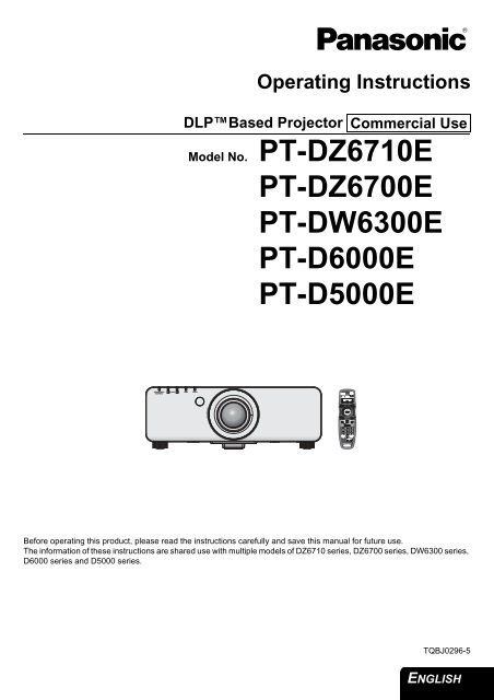
Operating Instructions<br />
DLPBased Projector<br />
LAMP TEMP FILTER<br />
Commercial Use<br />
Model No. <strong>PT</strong>-<strong>DZ6710E</strong><br />
<strong>PT</strong>-<strong>DZ6700E</strong><br />
<strong>PT</strong>-DW6300E<br />
<strong>PT</strong>-D6000E<br />
<strong>PT</strong>-D5000E<br />
Before operating this product, please read the instructions carefully and save this manual for future use.<br />
The information of these instructions are shared use with multiple models of DZ6710 series, DZ6700 series, DW6300 series,<br />
D6000 series and D5000 series.<br />
TQBJ0296-5<br />
ENGLISH
Important<br />
Information<br />
Important Safety Notice<br />
Dear <strong>Panasonic</strong> Customer:<br />
This instruction booklet provides all the necessary operating information that you might require. We hope it will help<br />
you to get the most out of your new product, and that you will be pleased with your <strong>Panasonic</strong> DLPBased projector.<br />
The serial number of your product may be found on its bottom. You should note it in the space provided below and<br />
retain this booklet in case service is required.<br />
ENGLISH - 2<br />
Model number: <strong>PT</strong>-<strong>DZ6710E</strong>/<strong>PT</strong>-<strong>DZ6700E</strong>/<strong>PT</strong>-DW6300E/<strong>PT</strong>-D6000E/<strong>PT</strong>-D5000E<br />
Serial number:<br />
WARNING: THIS APPARATUS MUST BE EARTHED.<br />
WARNING: To prevent damage which may result in fire or shock hazard, do not expose this appliance<br />
to rain or moisture.<br />
Machine Noise Information Ordinance 3. GSGV, January 18, 1991: The sound pressure level at the operator<br />
position is equal or less than 70 dB (A) according to ISO 7779.<br />
WARNING:<br />
1. Remove the plug from the mains socket when this unit is not in use for a prolonged period of time.<br />
2. To prevent electric shock, do not remove cover. No user serviceable parts inside. Refer servicing to qualified<br />
service personnel.<br />
3. Do not remove the earthing pin on the mains plug. This apparatus is equipped with a three prong earthingtype<br />
mains plug. This plug will only fit an earthing-type mains socket. This is a safety feature. If you are unable<br />
to insert the plug into the mains socket, contact an electrician. Do not defeat the purpose of the earthing plug.<br />
CAUTION: To assure continued compliance, follow the attached installation instructions, which includes using<br />
the provided power cord and shielded interface cables when connecting to computer or peripheral<br />
device. If you use serial port to connect PC for external control of projector, you must use optional<br />
RS-232C serial interface cable with ferrite core. Any unauthorized changes or modifications to this<br />
equipment will void the user’s authority to operate.<br />
Pursuant to at the directive 2004/108/EC, article 9(2)<br />
<strong>Panasonic</strong> Testing Centre<br />
<strong>Panasonic</strong> Service Europe, a division of <strong>Panasonic</strong> Marketing Europe GmbH<br />
Winsbergring 15, 22525 Hamburg, F.R. Germany
Important Safety Notice<br />
Information for Users on Collection and Disposal of Old Equipment and used<br />
Batteries<br />
These symbols on the products, packaging, and/or accompanying documents mean that used electrical<br />
and electronic products and batteries should not be mixed with general household waste.<br />
For proper treatment, recovery and recycling of old products and used batteries, please take them to<br />
applicable collection points, in accordance with your national legislation and the Directives 2002/96/EC<br />
and 2006/66/EC.<br />
By disposing of these products and batteries correctly, you will help to save valuable resources and<br />
prevent any potential negative effects on human health and the environment which could otherwise<br />
arise from inappropriate waste handling.<br />
For more information about collection and recycling of old products and batteries, please contact your<br />
local municipality, your waste disposal service or the point of sale where you purchased the items.<br />
Penalties may be applicable for incorrect disposal of this waste, in accordance with national legislation.<br />
For business users in the European Union<br />
If you wish to discard electrical and electronic equipment, please contact your dealer or supplier for<br />
further information.<br />
Information on Disposal in other Countries outside the European Union<br />
These symbols are only valid in the European Union. If you wish to discard these items, please contact<br />
your local authorities or dealer and ask for the correct method of disposal.<br />
Note for the battery symbol (bottom two symbol examples):<br />
This symbol might be used in combination with a chemical symbol. In this case it complies with the<br />
requirement set by the Directive for the chemical involved.<br />
<br />
Environment care information for users in China<br />
This symbol is only valid in China.<br />
ENGLISH - 3<br />
Important<br />
Information
Important<br />
Information<br />
Important Safety Notice<br />
IMPORTANT: THE MOULDED PLUG (U.K. only)<br />
FOR YOUR SAFETY, PLEASE READ THE FOLLOWING TEXT CAREFULLY.<br />
This appliance is supplied with a moulded three pin mains plug for your safety and convenience.<br />
A 13 amp fuse is fitted in this plug. Should the fuse need to be replaced, please ensure that the<br />
replacement fuse has a rating of13 amps and that it is approved by ASTA or BSI to BS1362.<br />
Check for the ASTA mark a or the BSI mark ` on the body of the fuse.<br />
If the plug contains a removable fuse cover, you must ensure that it is refitted when the fuse is<br />
replaced. If you lose the fuse cover, the plug must not be used until a replacement cover is<br />
obtained. A replacement fuse cover can be purchased from an Authorised Service Centre.<br />
If the fitted moulded plug is unsuitable for the mains socket in your home, then the fuse<br />
should be removed and the plug cut off and disposed of safely. There is a danger of severe<br />
electrical shock if the cut off plug is inserted into any 13 amp socket.<br />
If a new plug is to be fitted, please observe the wiring code as shown below.<br />
If in any doubt, please consult a qualified electrician.<br />
WARNING: THIS APPLIANCE MUST BE EARTHED.<br />
IMPORTANT: The wires in this mains lead are coloured in accordance with the following code:<br />
Green - and - Yellow: Earth<br />
Blue: Neutral<br />
Brown: Live<br />
As the colours of the wire in the mains lead of this appliance may not correspond with the coloured<br />
markings identifying the terminals in your plug, proceed as follows.<br />
ENGLISH - 4<br />
The wire which is coloured GREEN - AND - YELLOW must be connected to the<br />
terminal in the plug which is marked with the letter E or by the Earth symbol W or<br />
coloured GREEN or GREEN - AND - YELLOW.<br />
The wire which is coloured BLUE must be connected to the terminal in the plug which<br />
is marked with the letter N or coloured BLACK.<br />
The wire which is coloured BROWN must be connected to the terminal in the plug<br />
which is marked with the letter L or coloured RED.<br />
How to replace the fuse: Open the fuse compartment with a screwdriver and<br />
replace the fuse.<br />
13A250V BS1363/A<br />
L<br />
ASA<br />
HE-8<br />
N
Contents<br />
Quick steps<br />
1. Set up your projector<br />
See “Setting up” on page 16.<br />
2. Connect with other devices<br />
See the functional instructions in the<br />
CD-ROM that is provided with the<br />
projector.<br />
3. Prepare the Remote control<br />
See “Remote control” on page 14.<br />
4. Start projecting<br />
See “Projecting” on page 19.<br />
5. Adjust the image<br />
See “Menu Navigation” on page 24.<br />
Important Information<br />
Important Safety Notice..............................................2<br />
Precautions with regard to safety .............................6<br />
WARNINGS ...................................................................... 6<br />
CAUTIONS ....................................................................... 7<br />
Cautions when transporting .............................................. 9<br />
Cautions when installing ................................................... 9<br />
Cautions on use................................................................ 9<br />
Others ............................................................................. 10<br />
Security........................................................................... 10<br />
Accessories..................................................................... 11<br />
Preparation<br />
About Your Projector................................................12<br />
Projector body................................................................. 12<br />
Remote control................................................................ 14<br />
Getting Started<br />
Setting up.................................................................. 16<br />
Projection method........................................................... 16<br />
Removing and attaching the projection lens................... 17<br />
Mains lead ...................................................................... 18<br />
Basic Operation<br />
Projecting.................................................................. 19<br />
Projecting a image.......................................................... 19<br />
Remote control operation........................................ 21<br />
Operating range.............................................................. 21<br />
Setting up the image position automatically ................... 21<br />
Switching the input signal ............................................... 22<br />
Stopping the projection................................................... 22<br />
Clearing the on-screen menu ......................................... 22<br />
Changing the picture aspect ratio................................... 22<br />
Displaying the internal test pattern ................................. 22<br />
Using an assigned function ............................................ 23<br />
Displaying the status of the projector ............................. 23<br />
Resetting to the factory default....................................... 23<br />
Menu Navigation....................................................... 24<br />
Main menu and Sub-menu ............................................. 24<br />
Navigating through the menu ......................................... 27<br />
Maintenance<br />
Monitor Lamp indicators ......................................... 28<br />
Managing the indicated problems................................... 28<br />
Replacement ............................................................. 30<br />
Replacing the Lamp unit................................................. 30<br />
Replacing the Auto Cleaning Filter (ACF) ...................... 32<br />
Troubleshooting ....................................................... 33<br />
Appendix<br />
Technical Information .............................................. 34<br />
List of compatible signals ............................................... 34<br />
Specifications ................................................................. 36<br />
Ceiling mount bracket safeguards .................................. 38<br />
Dimensions..................................................................... 39<br />
Trademark acknowledgements ...................................... 39<br />
Index .......................................................................... 40<br />
ENGLISH - 5<br />
Important<br />
Information<br />
Appendix Maintenance Basic Operation Getting Started Preparation
Important<br />
Information<br />
Precautions with regard to safety<br />
WARNINGS<br />
If you notice smoke, strange smells or noise coming<br />
from the projector, disconnect the mains plug from<br />
the mains socket.<br />
Do not continue to use the projector in such cases,<br />
otherwise fire or electric shocks could result.<br />
Check that no more smoke is coming out, and then<br />
contact an Authorised Service Centre for repairs.<br />
Do not attempt to repair the projector yourself, as this<br />
can be dangerous.<br />
Do not install this projector in a place which is not<br />
strong enough to take the full weight of the<br />
projector.<br />
If the installation location is not strong enough, it may<br />
fall down or tip over, and severe injury or damage<br />
could result.<br />
Installation work (such as ceiling suspension)<br />
should only be carried out by a qualified technician.<br />
If installation is not carried out correctly, there is the<br />
danger that injury or electric shocks may occur.<br />
Do not use other than an authorised ceiling mount<br />
bracket.<br />
If foreign objects or water get inside the projector, or<br />
if the projector is dropped or the cabinet is broken,<br />
disconnect the mains plug from the mains socket.<br />
Continued use of the projector in this condition may<br />
result in fire or electric shocks.<br />
Contact an Authorised Service Centre for repairs.<br />
The mains socket shall be installed near the<br />
equipment and shall be easily accessible.<br />
Unplug the mains plug from the mains socket<br />
immediately when problem occurred.<br />
Do not overload the mains socket.<br />
If the power supply is overloaded (for example, by<br />
using too many adapters), overheating may occur<br />
and fire may result.<br />
Never attempt to modify or disassemble the<br />
projector.<br />
High voltages can cause fire or electric shocks.<br />
For any inspection, adjustment and repair work,<br />
please contact an Authorised Service Centre.<br />
Clean the mains plug regularly to prevent it from<br />
becoming covered in dust.<br />
If dust builds up on the mains plug, the resulting<br />
humidity can damage the insulation, which could<br />
result in fire. Pull the mains plug out from the mains<br />
socket and wipe it with a dry cloth.<br />
If not using the projector for an extended period of<br />
time, pull the mains plug out from the mains socket.<br />
Do not handle the mains plug with wet hands.<br />
Failure to observe this may result in electric shocks.<br />
ENGLISH - 6<br />
Insert the mains plug securely into the mains socket.<br />
Do not use other than the provided mains lead.<br />
If the plug is not inserted correctly, electric shocks or<br />
overheating could result.<br />
Do not use plugs which are damaged or mains<br />
sockets which are coming loose from the wall.<br />
Do not place the projector on top of surfaces which<br />
are unstable.<br />
If the projector is placed on top of a surface which is<br />
sloped or unstable, it may fall down or tip over, and<br />
injury or damage could result.<br />
Do not place the projector into water or let it become<br />
wet.<br />
Failure to observe this may result in fire or electric<br />
shocks.<br />
Do not do anything that might damage the mains<br />
lead or the mains plug.<br />
Do not damage the mains lead, make any<br />
modifications to it, place it near any hot objects, bend<br />
it excessively, twist it, pull it, place heavy objects on<br />
top of it or wrap it into a bundle.<br />
If the mains lead is used while damaged, electric<br />
shocks, short-circuits or fire may result.<br />
Ask an Authorised Service Centre to carry out any<br />
repairs to the mains lead that might be necessary.<br />
Do not place the projector on soft materials such as<br />
carpets or sponge mats.<br />
Doing so may cause the projector to overheat, which<br />
can cause burns, fire or damage to the projector.<br />
Do not place liquid containers on top of the<br />
projector.<br />
If water spills onto the projector or gets inside it, fire<br />
or electric shocks could result.<br />
If any water gets inside the projector, contact an<br />
Authorised Service Centre.<br />
Do not insert any foreign objects into the projector.<br />
Do not insert any metal objects or flammable objects<br />
into the projector or drop them onto the projector, as<br />
doing so can result in fire or electric shocks.<br />
Do not allow the + and - terminals of the batteries to<br />
come into contact with metallic objects such as<br />
necklaces or hairpins.<br />
Failure to observe this may cause the batteries to<br />
leak, overheat, explode or catch fire.<br />
Store the batteries in a plastic bag and keep them<br />
away from metallic objects.
Do not touch the leaked liquid from the batteries.<br />
If you touch the leaked liquid, it may hurt your skin.<br />
Immediately wash away the liquid with water and<br />
seek medical advice.<br />
If you get the leaked liquid in your eye, it may cause<br />
blindness or damage. Never rub your eye, and<br />
immediately wash away the liquid with water and<br />
seek medical advice.<br />
During a thunderstorm, do not touch the projector or<br />
the cable.<br />
Electric shocks can result.<br />
Do not use the projector in a bath or shower.<br />
Fire or electric shocks can result.<br />
Do not place your skin into the light beam while the<br />
projector is being used.<br />
Strong light is emitted from the projector’s lens. If you<br />
place directly into this light, it can hurt or damage<br />
your skin.<br />
Do not look into the lens while the projector is being<br />
used.<br />
Strong light is emitted from the projector’s lens. If you<br />
look directly into this light, it can hurt and damage<br />
your eyes.<br />
Do not disassemble the lamp unit.<br />
If the lamp section breaks, it may cause injury.<br />
Do not place your hands or other objects close to the<br />
air outlet port.<br />
Heated air comes out of the air outlet port. Do not<br />
place your hands or face, or objects which cannot<br />
withstand heat close to this port [allow at least<br />
50 cm (20") of space], otherwise burns or damage<br />
could result.<br />
Replacement of the lamp should be carried out by a<br />
qualified technician.<br />
The lamp has high internal pressure. If improperly<br />
handled, explosion might result.<br />
The lamp can easily become damaged if struck<br />
against hard objects or dropped, and injury or<br />
malfunctions may result.<br />
CAUTIONS<br />
Do not cover the air inlet port or the air outlet port.<br />
Doing so may cause the projector to overheat, which<br />
can cause fire or damage to the projector.<br />
Do not place the projector in narrow, badly ventilated<br />
places such as closets or bookshelves.<br />
Do not place the projector on cloth or papers, as<br />
these materials could be drawn into the air inlet port.<br />
Precautions with regard to safety<br />
When replacing the lamp, allow it to cool for at least<br />
one hour before handling it.<br />
The lamp cover gets very hot, and touching it can<br />
cause burns.<br />
Before replacing the lamp, be sure to disconnect the<br />
mains plug from the mains socket.<br />
Electric shocks or explosions can result if this is not<br />
done.<br />
Do not allow infants or pets to touch the remote<br />
control unit.<br />
Keep the remote control unit out of the reach of<br />
infants and pets after using it.<br />
After removing the battery from remote control unit,<br />
keep it away from the reach of children.<br />
The battery can cause death by suffocation if<br />
swallowed.<br />
If the battery is swallowed, seek medical advice<br />
immediately.<br />
Insulate the battery using tape or similar before<br />
disposal.<br />
If the battery comes into contact with metallic objects<br />
or other batteries, it may catch fire or explode.<br />
When installing to a ceiling, be sure to use the<br />
accessory wire (install in a different location to the<br />
ceiling mount bracket) and the eye bolts as an extra<br />
preventative measure to stop the projector from<br />
falling down.<br />
If the projector is not secure enough, accidents may<br />
result.<br />
Do not place sets directly on top of each other.<br />
If this is not observed, accidents may result.<br />
Do not use the projector while the projection lens<br />
cover is still attached to the projection lens.<br />
If this is not observed, fire may occur.<br />
Do not set up the projector in humid or dusty places<br />
or in places where the projector may come into<br />
contact with oily smoke or steam.<br />
Using the projector under such conditions may result<br />
in fire, electric shocks or plastic deterioration. The<br />
plastic deterioration may cause the falling down of<br />
the projector which is mounted on the ceiling.<br />
ENGLISH - 7<br />
Important<br />
Information
Important<br />
Information<br />
Precautions with regard to safety<br />
Do not set up the projector in a high temperature<br />
environment, such as near a heater or in direct<br />
sunlight.<br />
Failure to observe this may result in fire, malfunction<br />
or plastic deterioration.<br />
Do not set up the projector outdoors.<br />
The projector is designed for indoor use only.<br />
When disconnecting the mains lead, hold the plug,<br />
not the lead.<br />
If the mains lead itself is pulled, the lead will become<br />
damaged, and fire, short-circuits or serious electric<br />
shocks may result.<br />
Always disconnect all cables before moving the<br />
projector.<br />
Moving the projector with cables still attached can<br />
damage the cables, which could cause fire or electric<br />
shocks to occur.<br />
Do not place any heavy objects on top of the<br />
projector.<br />
Failure to observe this may cause the projector to<br />
become unbalanced and fall, which could result in<br />
damage or injury.<br />
Do not short-circuit, heat or disassemble the<br />
batteries or place them into water or fire.<br />
Failure to observe this may cause the batteries to<br />
overheat, leak, explode or catch fire, and burns or<br />
other injury may result.<br />
When inserting the batteries, make sure the<br />
polarities (+ and -) are correct.<br />
If the batteries are inserted incorrectly, they may<br />
explode or leak, and fire, injury or contamination of<br />
the battery compartment and surrounding area may<br />
result.<br />
Use only the specified batteries.<br />
If incorrect or different kind of batteries are used, they<br />
may explode or leak, and fire, injury or contamination<br />
of the battery compartment and surrounding area<br />
may result.<br />
Do not mix old and new batteries.<br />
If the batteries are used mixing old and new, they<br />
may explode or leak, and fire, injury or contamination<br />
of the battery compartment and surrounding area<br />
may result.<br />
Remove the used batteries from the remote control<br />
promptly.<br />
If you leave used batteries in the remote control for<br />
an extended period of time, it may cause liquid<br />
leaking, abnormal internal temperature rising or<br />
explosion.<br />
ENGLISH - 8<br />
If not using the projector for an extended period of<br />
time, disconnect the mains plug from the mains<br />
socket and remove the batteries from the remote<br />
control.<br />
If dust builds up on the mains plug, the resulting<br />
humidity may damage the insulation, which could<br />
result in fire.<br />
Keeping or leaving the remote control with batteries<br />
inside may cause insulation deterioration, electrical<br />
leakage or explosion which could result in fire.<br />
Do not use the old lamp unit.<br />
The lamp section may break.<br />
Do not put your weight on this projector.<br />
You could fall or the projector could break, and injury<br />
may result.<br />
Be especially careful not to let young children stand<br />
or sit on the projector.<br />
Disconnect the mains plug from the mains socket as<br />
a safety precaution before carrying out any cleaning.<br />
Electric shocks can result if this is not done.<br />
If the lamp has broken, ventilate the room<br />
immediately. Do not touch or bring your face close<br />
to the broken pieces.<br />
Failure to observe this may cause the user to absorb<br />
the gas which was released when the lamp broke and<br />
which contains nearly the same amount of mercury<br />
as fluorescent lamps, and the broken pieces may<br />
cause injury.<br />
If you believe that you have absorbed the gas or that<br />
the gas has got into your eyes or mouth, seek<br />
medical advice immediately.<br />
Ask your dealer about the replacement of the lamp<br />
unit and check the inside of the projector.<br />
Ask an Authorised Service Centre to clean inside the<br />
projector at least once a year.<br />
If dust is left to build up inside the projector without<br />
being cleaned out, it can result in fire or problems<br />
with operation.<br />
It is a good idea to clean the inside of the projector<br />
before the season for humid weather arrives. Ask<br />
your nearest Authorised Service Centre to clean the<br />
projector when required. Please discuss with the<br />
Authorised Service Centre regarding cleaning costs.<br />
Do not use chemical treated wipes when cleaning.<br />
Using chemical treated wipes may result in plastic<br />
distortion or deterioration.
Do not reach for the openings beside the optical<br />
lens, during horizontal or vertical movements of the<br />
lens.<br />
Failure to observe this may cause injury.<br />
Precautions with regard to safety<br />
Replacement of the lamp unit should only be carried<br />
out after it has completely cooled off.<br />
Failure to observe this may cause burns.<br />
We are constantly making efforts to preserve and maintain a clean environment. Please take non repairable<br />
units back to your dealer or a recycling company.<br />
Cautions when transporting<br />
Do not subject the projector to excessive vibration<br />
or shocks.<br />
The projector lens need to be handled with care.<br />
Cover the lens with the lens cover when transporting<br />
the projector.<br />
Cautions when installing<br />
Avoid setting up in places which are subject to<br />
vibration or shocks.<br />
The internal parts can be damaged, which may cause<br />
malfunctions or accidents.<br />
Avoid setting up in places which are subject to<br />
sudden temperature changes, such as near an air<br />
conditioner or lighting equipment.<br />
The life of the lamp may be shortened or the projector<br />
may be turned off. See “TEMP indicator” on page 28.<br />
Do not set up the projector near high-voltage power<br />
lines or near motors.<br />
The projector may be subject to electromagnetic<br />
interference.<br />
Cautions on use<br />
In order to get the best picture quality<br />
Draw curtains or blinds over any windows and turn off<br />
any lights near the screen to prevent outside light or<br />
light from indoor lamps from shining onto the screen.<br />
In rare cases, wafture can occur on the screen<br />
affected by the warm air from the exhaust port<br />
depending on the environment. Make sure that there<br />
is no equipment in front of the set which will<br />
recirculate the exhaust air from the set or other<br />
nearby equipment.<br />
When transporting the projector, hold the body at<br />
the bottom securely.<br />
Do not hold the adjuster legs or the top cover to move<br />
the projector, as this may damage the projector.<br />
Be sure to always remove the lens during transport.<br />
The projection lens is susceptible to vibrations and<br />
impacts.<br />
If installing the projector to the ceiling, ask a<br />
qualified technician to carry out all installation work.<br />
You will need to purchase the separate installation kit<br />
(Model No. ET-PKD56H, ET-PKD55S). Furthermore,<br />
all installation work is should only be carried out by a<br />
qualified technician.<br />
If using this projector at high elevations 1 400 -<br />
2 700 m (4 593 - 8 858 ft) sea level, set the HIGH<br />
ALTITUDE MODE to ON.<br />
Failure to observe this may result in malfunctions or<br />
the life of the lamp or the other components may be<br />
shortened.<br />
Be sure to install the projection lens cover after<br />
installing the projection lens.<br />
If this not done, dust will collect inside the projector<br />
and problems with the projector will result.<br />
Do not touch the surfaces of the lens or the front<br />
glass with your bare hands.<br />
If the surface of the lens becomes dirty from<br />
fingerprints or anything else, this will be magnified<br />
and projected onto the screen. Moreover, when not<br />
using the projector, close the front panel cover.<br />
ENGLISH - 9<br />
Important<br />
Information
Important<br />
Information<br />
Precautions with regard to safety<br />
The projector has a high pressure mercury lamp and<br />
that is characterised as follows.<br />
The brightness of the lamp depends on the duration<br />
of use.<br />
The lamp may explode or shorten the lamp life by<br />
shocks or chipping damage.<br />
The lamp may explode only occasionally after using<br />
the projector.<br />
The lamp may explode if using the projector after the<br />
instructed lamp replacement timing.<br />
When the lamp exploded, it emits internal smoke-like<br />
gas.<br />
The lamp life is depends on individual lamp<br />
characteristics, usage condition and the installation<br />
environment. Especially the consecutive use of the<br />
projector for more than 22 hours, or the frequent<br />
switching on or off may greatly affect on the lamp life.<br />
Provide a lamp for replacement in advance.<br />
Others<br />
Disposal<br />
When disposing of the product, contact your nearest<br />
municipality or dealer to confirm the correct<br />
procedure for disposal.<br />
Security<br />
Take the safety measures for use of the projector<br />
that should cover the following envisioned<br />
incidents.<br />
The leakage of your personal registered information.<br />
Dishonest operation by an untrusted third party.<br />
Locking out or prevent anyone else from using the<br />
projector by an untrusted third party.<br />
ENGLISH - 10<br />
Optical components<br />
If you use the projector consecutively 22 hours every<br />
day, the optical components may need to be replaced<br />
in less than 1 year.<br />
Do not use projectors with the adjustable feet or<br />
projection lens cover removed.<br />
If this is not observed, the sets may not operate<br />
correctly or accidents may result.<br />
DLP chips<br />
The DLP chips are made using extremely highprecision<br />
technology. Note that in rare cases, pixels<br />
may be missing or always lit, but this is not a<br />
malfunction.<br />
Connection to external device<br />
When connecting the projector to a computer or<br />
external device, use the power cord supplied with the<br />
corresponding device and a commercially available<br />
shielded interface cable.<br />
Security instruction<br />
The connecting network must be secured by firewall<br />
or others.<br />
Change your password regularly.<br />
Do not use password too simple to guess.<br />
The Authorised Service Centre will never ask you for<br />
the password.<br />
Do not share your password with anyone else.<br />
Password the projector and restrict access to<br />
authorized users only.
Accessories<br />
Make sure the following accessories are provided with your projector.<br />
Remote control (x1)<br />
N2QAYB000371<br />
AA batteries for remote<br />
control (x2)<br />
Projector lens cover (x1)<br />
TKKL5244-1<br />
Power cord secure lock<br />
(x1)<br />
TTRA0183<br />
Precautions with regard to safety<br />
Safety cable (x1),<br />
Washers (x2)<br />
TTRA0214<br />
Lens cover (x1)<br />
TKPB35101A<br />
CD-ROM (x1)<br />
TQBH9013<br />
Mains lead (x1)<br />
K2CM3FZ00003<br />
Mains lead (x1)<br />
K2CT3FZ00003<br />
* The protectors for enclosed products, such as a plug cover or foam cartons, must be treated properly.<br />
* Contact to an Authorised Service Centre for lost accessories.<br />
ENGLISH - 11<br />
Important<br />
Information
Preparation<br />
About Your Projector<br />
Projector body<br />
Top, front and bottom view<br />
Indicators<br />
Power indicator<br />
Lamp1 (LAMP1) indicator (page 28)<br />
Lamp2 (LAMP2) indicator (page 28)<br />
Temperature (TEMP) indicator (page 28)<br />
Filter (FILTER) indicator (page 29)<br />
STANDBY(RED)/<br />
ON(GREEN)<br />
STANDBY(RED)/<br />
ON(GREEN)<br />
LAMP TEMP FILTER<br />
NOTE:<br />
• Do not cover the ventilation openings or place anything within 50 cm (20") of them as this may cause damage or injury.<br />
• While the projector is not in use, keep the projector lens cover attached to protect the lens.<br />
ENGLISH - 12<br />
LAMP TEMP FILTER<br />
Remote control signal<br />
receptor (page 21)<br />
Front leg adjusters<br />
Screw up/down to adjust the<br />
projection angle.<br />
Burglar hook port<br />
Attach a commercial burglar<br />
prevention cable.<br />
Projection lens<br />
Focus ring<br />
Input select buttons<br />
These buttons select the<br />
RGB1, RGB2, DVI-D, VIDEO,<br />
S-VIDEO and SDI<br />
(<strong>PT</strong>-<strong>DZ6710E</strong> only) terminals.<br />
(page 19)<br />
Lamp unit compartment (page 30)<br />
POWER ON button<br />
Starts the projection while<br />
in the standby mode.<br />
(page 19)<br />
POWER STANDBY<br />
button<br />
Returns to the standby<br />
mode. (page 20)<br />
Air exhaust port<br />
AUTO SETUP button<br />
Pressing this button while projecting an image<br />
automatically corrects the picture positioning on<br />
the screen. While the auto setup feature is active,<br />
a message “PROGRESS” appears on the screen.<br />
(page 21)<br />
Remote control signal receptor (page 21)<br />
SHUTTER button<br />
Pressing this button toggles the projector’s<br />
internal mechanical shutter to black out the<br />
projector. (page 22)<br />
MENU button<br />
Displays and clears the main<br />
menu, and returns to the<br />
previous menu when the menu<br />
is displayed. (page 27)<br />
LENS button<br />
This button is used together with<br />
F G I H to adjust focus, zoom<br />
and shift by the projection lens.<br />
(page 19)<br />
Navigation and<br />
ENTER buttons<br />
Navigate through<br />
the menu items<br />
with F G I H,<br />
and activate them<br />
with the ENTER<br />
button. (page 27)
Side views<br />
S-VIDEO IN<br />
Connect an S-VIDEO signals.<br />
(Mini DIN 4 pin)<br />
VIDEO IN<br />
Connect a video signals.<br />
(BNC)<br />
LAN<br />
Connect a LAN cable for network<br />
connection.<br />
(RJ-45)<br />
REMOTE 1 IN/OUT<br />
When two or more main<br />
units are used in the system,<br />
they can be connected and<br />
controlled with wired remote<br />
control cable.<br />
(M3 jack)<br />
REMOTE 2<br />
Connect a cable from an<br />
external control circuit.<br />
(D-sub 9 pin female)<br />
POWER button<br />
Switch the projector on/off. (page 19)<br />
SERIAL IN/SERIAL OUT<br />
Connect an RS-232C cable<br />
from/to a computer.<br />
Air intake port Air intake port<br />
Auto Cleaning Filter (ACF) compartment (page 32)<br />
About Your Projector<br />
RGB 1 IN<br />
Connect an RGB or YPBPR signals.<br />
(3, 4 or 5 wire BNC)<br />
RGB 2 IN<br />
Connect an RGB or YPBPR signals.<br />
(D-SUB 15 pin female)<br />
DVI-D IN<br />
Connect a single link DVI-D signals.<br />
(DVI-D 24 pin)<br />
SDI IN (<strong>PT</strong>-<strong>DZ6710E</strong> only)<br />
Connect a cable from a<br />
computer.<br />
(BNC)<br />
AC IN terminal<br />
Connect the main lead to supply<br />
electronic power to the projector.<br />
(page 19)<br />
Security lock<br />
Attach the commercial shackle lock, manufactured<br />
by Kensington, to protect your projector.<br />
Compatible with the Kensington MicroSaver<br />
Security System.<br />
NOTE:<br />
• Switch on the POWER button of the projector body that is located near the terminals before using the control buttons.<br />
• Do not touch the LAN terminal with your bare hands or body, as body parts may have charged static electricity. Failure to do so may<br />
cause malfunctions. Do not touch the metallic parts of LAN terminal and cable.<br />
• Please connect the LAN to indoor devices only.<br />
ENGLISH - 13<br />
Preparation
Preparation<br />
About Your Projector<br />
Remote control<br />
POWER ON and POWER STANDBY<br />
buttons<br />
POWER ON: Starts<br />
the projection while in<br />
the standby mode.<br />
POWER STANDBY: Returns to the<br />
standby mode. (page 19)<br />
INPUT SELECT buttons<br />
These buttons<br />
select the RGB1,<br />
RGB2, DVI-D,<br />
VIDEO, S-VIDEO<br />
and SDI terminals. (page 22)<br />
MENU buttons<br />
Displays and clears the main<br />
menu, and returns to the<br />
previous menu when the menu<br />
is displayed. (page 27)<br />
ON SCREEN button<br />
Displays and clears the on<br />
screen indications. (page 22)<br />
TEST PATTERN button<br />
Displays the test pattern.<br />
(page 22)<br />
Numeric (0 - 9) buttons<br />
Enter ID number of the remote control<br />
and adjustment values of menu items.<br />
(page 15)<br />
STATUS button<br />
Displays projector<br />
information. (page 23)<br />
Navigation and ENTER buttons<br />
Navigate through the<br />
menu items with F G<br />
I H, and activate them<br />
with the ENTER button.<br />
(page 27)<br />
Top view<br />
Remote control signal emitters<br />
ENGLISH - 14<br />
Remote control indicator<br />
Flashes by pressing any buttons.<br />
(page 21)<br />
AUTO SETUP<br />
Pressing this button while<br />
projecting an image<br />
automatically corrects the<br />
picture positioning on the screen.<br />
While the auto setup feature is active,<br />
a message “PROGRESS” appears on<br />
the screen. (page 21)<br />
SHUTTER button<br />
Pressing this button toggles<br />
the projector’s internal<br />
mechanical shutter to black out<br />
the projector. (page 22)<br />
ASPECT button<br />
Switches the image aspect<br />
ratio. (page 22)<br />
LENS buttons<br />
These buttons<br />
are used<br />
together with<br />
F G I H to adjust focus, zoom and<br />
shift by the projection lens. (page 19)<br />
FUNCTION button<br />
Assign the frequently use<br />
functions from options for<br />
shortcut. (page 23)<br />
DEFAULT button<br />
Restores the default factory<br />
setting. (page 23)<br />
ID buttons<br />
ALL: Makes the remote<br />
control available to<br />
control any ID<br />
projectors.<br />
SET: Specifies the ID of the remote<br />
control. (page 15)<br />
A<br />
Bottom view<br />
Remote control wired terminal Battery compartment<br />
1.Press the tab and lift up the cover.<br />
2.Insert the batteries according to the polarity<br />
diagram indicated inside.<br />
NOTE:<br />
• Switch on the POWER button of the projector body that is located near the terminals before using the remote control.<br />
• Do not drop the remote control.<br />
• Avoid contact with liquids or moisture.<br />
• Use manganese batteries with the remote control.<br />
• Do not attempt to modify or disassemble the remote control. Contact an Authorised Service Centre for repairs.<br />
• Do not keep pressing the remote control buttons as this may shorten battery life.<br />
• See “Remote control operation” on page 21.<br />
B
Setting projector ID number to<br />
remote control<br />
Each projector can be assigned a unique 2 digits ID<br />
number, and the remote control 2 digits ID number must<br />
be set to match the intended projector. The default<br />
setting of the projector ID is ALL. Set the ID of the<br />
projector in advance from the menu items.<br />
1.Press the ID SET button.<br />
Displays the projector ID number on the screen.<br />
2.Within 5 seconds, enter the same number of the required<br />
projector by pressing the numeric buttons.<br />
ID number range: 01 - 64<br />
NOTE:<br />
• Do not press the ID SET button accidentally or carelessly<br />
because the ID number on the remote control can be set even<br />
when no projector is around.<br />
• If you do not enter the 2 digits ID number within 5 seconds<br />
after the ID SET button has been pressed, the ID will remain at<br />
the number that was set before the ID SET button was<br />
pressed.<br />
• Your specified ID will be erased if the batteries of the remote<br />
control are left exhausted. When the batteries are replaced,<br />
set the same ID number again.<br />
About Your Projector<br />
Using a wired remote control<br />
When multiple projectors are connected as part of the<br />
system, connect to units with a M3 stereo mini jack<br />
commercial cable to simultaneously control multiple main<br />
units with a single remote control through the REMOTE 1<br />
IN/OUT terminal. It is effective to use the wired remote<br />
control in the environment in which an obstacle stands in<br />
the light path or where devices are susceptible to outside<br />
light.<br />
M3 stereo mini jack<br />
(commercial)<br />
Connect to the remote<br />
control wired terminal<br />
Connect to another<br />
projector<br />
NOTE:<br />
• Use 2 core shielded cable of length of 15 m or less. If the<br />
length of the cable exceeds 15 m (49'2"), the shielding of the<br />
cable may not be sufficient and the remote control may not<br />
work.<br />
ENGLISH - 15<br />
Preparation
Getting Started<br />
Setting up<br />
Projection method<br />
You can use the projector with any of the following 4 projection methods. To set the desired method in the projector,<br />
Setting on a desk/floor and<br />
projecting from front<br />
INSTALLATION: FRONT/FLOOR<br />
COOLING CONDITION: FLOOR SETTING<br />
Setting on a desk/floor and<br />
projecting from rear<br />
INSTALLATION: REAR/FLOOR<br />
COOLING CONDITION: FLOOR SETTING<br />
Cautions when setting the projectors<br />
When placing the projector in confined space, a ventilation or air conditioning system must be equipped, and keep enough<br />
ventilation space on the rear and both sides of the projector.<br />
ENGLISH - 16<br />
Mounting on the ceiling and<br />
projecting from front<br />
INSTALLATION: FRONT/CEILING<br />
COOLING CONDITION: CEILING SETTING<br />
Mounting on the ceiling and<br />
projecting from rear<br />
INSTALLATION: REAR/CEILING<br />
COOLING CONDITION: CEILING SETTING<br />
NOTE:<br />
• A translucent screen is required for rear projection.<br />
• See more detailed setting up instructions, INSTALLATION and COOLING CONDITION in PROJECTOR SETUP menu on the functional<br />
instructions in the CD that is provided with the projector.<br />
• Do not place or use a projector on top of another projector.<br />
over 50 cm (20") over 50 cm (20") over 50 cm (20")<br />
over 10 cm (4")<br />
NOTE:<br />
• Do not stack the projectors without using frame or shelf.<br />
• Do not cover the ventilation openings or place anything within 50 cm (20") of them as this may cause<br />
damage or injury.<br />
• Avoid heating or cooling air of the air conditioning systems directly blow on to the projector ventilation<br />
openings.<br />
• You can tilt the projector within ± 15 degrees horizontally.<br />
STANDBY(RED)/<br />
ON(GREEN)<br />
STANDBY(RED)/<br />
ON(GREEN)<br />
LAMP TEMP FILTER<br />
LAMP TEMP FILTER
Removing and attaching the projection lens<br />
Removing the projection lens<br />
from the projector<br />
1. Switch off the POWER button on the projector.<br />
2. Rotate the lens cover counterclockwise and remove.<br />
3. While pressing the lens release button, rotate the<br />
projection lens counterclockwise, and remove the<br />
projection lens.<br />
Lens release button<br />
Lens cover<br />
Projection lens<br />
NOTE:<br />
• Do not touch the lens signal receiver. Dust or dirt may cause<br />
defective contact.<br />
• Do not touch the surface of the projection lens with your bare<br />
hands.<br />
• Store the replaced lens where it will be free from vibration and<br />
impact.<br />
Setting up<br />
Attaching the projection lens to<br />
the projector<br />
1. Switch off the POWER button on the projector.<br />
When the lens cover is attached, rotate counterclockwise<br />
and remove.<br />
2. Align the guide of the projection lens with the guide<br />
groove in the projector, and then insert the lens.<br />
3. Rotate the projection lens clockwise until it clicks into<br />
place.<br />
4. To attach the slot, align the slot of the lens cover (see *1)<br />
with the arrow tip located on the body of the projector<br />
(see *2). Rotate clockwise until it reaches the arrow’s<br />
end mark (see *3) to attach.<br />
*3<br />
*2<br />
*1<br />
Lens cover<br />
NOTE:<br />
• Make sure the projection lens is attached securely by rotating<br />
the projection lens counterclockwise.<br />
ENGLISH - 17<br />
Getting Started
Getting Started<br />
Setting up<br />
Mains lead<br />
Connecting<br />
1. Make sure the shape of the mains plug and the AC IN<br />
terminal on the back of the projector match, then push<br />
the plug all the way in.<br />
2. Align the side of the “power cord secure lock” with the<br />
side guide rail of the AC IN terminal of the projector and<br />
slide it in.<br />
3. Place the latch to the latch catcher and press until it<br />
clicks.<br />
Latch<br />
4. Connect the mains lead to a mains socket.<br />
ENGLISH - 18<br />
Rail guide<br />
Disconnecting<br />
1. Unplug the mains lead from the mains socket.<br />
2. Depress the latch and slide the cover off.<br />
Latch<br />
3. Slide the “power cord secure lock” up along the side<br />
guide rail and remove.<br />
Rail guide<br />
4. Hold the plug and unplug the mains lead from the AC IN<br />
terminal on the back of the projector.<br />
Power indicator lights in orange if the internal cooling fan is<br />
still operating by internal power supply.<br />
NOTE:<br />
• Do not use other than the provided mains lead.<br />
• Ensure all the input devices are connected and turned off before connecting the mains lead.<br />
• Do not force the connector as this may damage the projector and/or the mains lead.<br />
• Dirt or dust build-up around plugs may cause fire or electrical hazards.<br />
• Switch off the power to the projector when not in use.<br />
• If the projector is switched on again while the internal cooling fan is still operating by the internal power supply, it may take a while to start<br />
the projection.
Projecting<br />
Switching on the projector<br />
.<br />
Projecting a image<br />
When using an optional lens, install a projection lens<br />
before switch on the projector.<br />
1. Connect the supplied mains lead (220 - 240 V AC,<br />
50 Hz/60 Hz) to the AC IN terminal.<br />
2. Remove the projection lens cover from the lens.<br />
3. Switch the POWER switch on that is on the side of the<br />
projector.<br />
The power indicator lamp on the projector will flash in red.<br />
After a short period, the indicator will illuminate and the<br />
projector will enter standby mode.<br />
POWER switch AC IN terminal<br />
4. Press the POWER ON button<br />
The power indicator lamp illuminates in green and soon the<br />
image is projected on the screen.<br />
POWER ON button<br />
NOTE:<br />
• If the projector is powered up at about 0 °C (32 °F), a warmup<br />
period of approximately 5 minutes may be necessary to<br />
start projection. The temperature monitor (TEMP) lamp lights<br />
up during the warm-up period. When the warm-up is<br />
completed, the temperature monitor (TEMP) lamp turns off<br />
and the image is projected on the screen.<br />
• If the temperature of the operating environment is low and<br />
warm-up takes more than 5 minutes, the projector will judge<br />
that a problem has occurred and the power will be turned off<br />
automatically. If this happens, increase the temperature<br />
around the projector so that it is 0 °C (32 °F) or higher, and<br />
then turn on the POWER switch and press the POWER ON<br />
button again.<br />
Making adjustment and selection<br />
It is recommended that the projector be allowed to warm<br />
up for at least 30 minutes before any adjustments are<br />
made to the focus.<br />
1. Roughly adjust the focus of the lens.<br />
2. Select and set the projection scheme of<br />
INSTALLATION and COOLING CONDITION settings in<br />
PROJECTOR SETUP menu.<br />
3. Select the input signal by pressing the INPUT SELECT<br />
buttons.<br />
4. Adjust the vertical tilt of the projector with the front leg<br />
adjusters.<br />
5. Adjust the shift position of the projection.<br />
If the input signal is RGB signal, additionally press the<br />
AUTO SETUP button to adjust the position of the image.<br />
6. Zoom the lens so the image fills the screen.<br />
7. Readjust the focus.<br />
8. Readjust the zoom so that the image size fits in the<br />
screen.<br />
Adjusting focus, zoom and shift<br />
Control buttons of the<br />
projector<br />
Remote control buttons<br />
Pressing the LENS button changes the<br />
setup screen in order of FOCUS, ZOOM<br />
and SHIFT. Press F G I H to adjust.<br />
Press FOCUS, ZOOM or SHIFT button<br />
to display the setup screen. Press F G<br />
I H to adjust.<br />
INPUT SELECT buttons<br />
LENS button<br />
CAUTION:<br />
• Be careful not to catch your fingers between the lens and<br />
shroud when shifting the lens.<br />
NOTE:<br />
• The setup screen will be displayed with the optional fixed lens<br />
though, it will not be functioning.<br />
• Pressing F G I or H for 3 seconds or more, performance<br />
the adjustment faster.<br />
ENGLISH - 19<br />
Basic Operation
Basic Operation<br />
Projecting<br />
Switching off the projector<br />
1. Press the POWER STANDBY button.<br />
The confirmation screen will be displayed.<br />
2. Select OK and press the ENTER button, or press the<br />
POWER STANDBY button again.<br />
The projection of the image stops, and the power indicator<br />
of the projector lights up orange. The cooling fan keeps<br />
running.<br />
3. When the power indicator of the projector turns to red,<br />
switch the POWER switch to OFF.<br />
When the power indicator of the projector turns to red, the<br />
cooling fan stops.<br />
While the cooling fan is still running, never turn off the<br />
POWER switch, nor unplug the mains lead from the mains<br />
socket.<br />
Direct power off function<br />
The power supplied internally causes the cooling fan to<br />
continue operating and cool off in the event that the<br />
power has failed or even after the mains lead is<br />
accidentally disconnected immediately after the power<br />
has been turned off.<br />
ENGLISH - 20<br />
POWER STANDBY button<br />
NOTE:<br />
• In the cooling state after the power is turned off, the lamp will<br />
not light up even if the power is turned on. To light up the lamp,<br />
turn on the power supply again when the lamp has been<br />
cooled sufficiently. Failure to observe this may shorten the<br />
lamp life.<br />
NOTE:<br />
• When the lamp has been cooled by the direct power off<br />
function, it sometimes takes longer than usual for the lamp to<br />
light up again.<br />
• While the cooling fan is operating, do not place the projector<br />
inside a box or bag.<br />
Lens home position<br />
1. Press and hold the LENS button of the control button on<br />
the projector or SHIFT button of the remote control for<br />
3 seconds or more.<br />
The HOME POSITION setup screen will be displayed for<br />
5 seconds.<br />
2. Press the ENTER button before the setup screen<br />
disappeared.<br />
While the lens returning to the home position, a message<br />
“PROGRESS” appears on the screen.<br />
NOTE:<br />
• The home position for the projection lens is the lens position<br />
when the lens is being replaced or when the projector is being<br />
stored away, and it is not the optical centre of the screen.<br />
Adjustment range after lens<br />
position (optical shift)<br />
Do not move the lens beyond the bounds of the shift<br />
range as this may cause a change in the focus. This<br />
limitation is to protect the parts of the projector. Using the<br />
standard projection position as the reference, the optical<br />
axis shift function makes it possible to adjust the<br />
projection position in the ranges shown in the figures<br />
below.<br />
<strong>PT</strong>-<strong>DZ6710E</strong>/<strong>PT</strong>-<strong>DZ6700E</strong>/<strong>PT</strong>-D6000E/<br />
<strong>PT</strong>-D5000E<br />
Standard projection position<br />
<strong>PT</strong>-DW6300E<br />
Standard projection position
Remote control operation<br />
Input select buttons<br />
On screen button<br />
Test pattern button<br />
Status button<br />
Shutter button<br />
Auto setup button<br />
Function button<br />
Aspect button<br />
Operating range<br />
You can operate the projector with the remote control within the<br />
remote range 30 m (98'5"), approximately ± 30° horizontally<br />
and ± 15° vertically.<br />
Facing to the projector<br />
Ensure the remote control emitter is facing to the remote<br />
control signal receptor on front/back of the projector and<br />
press the required buttons to operate.<br />
Facing to the screen<br />
Setting up the image position automatically<br />
Ensure the remote control emitter is facing to the screen<br />
and press the required buttons to operate the projector.<br />
The signal will be reflected off the screen. The operating<br />
range may differ due to the screen material. This<br />
function may not be effective with a translucent screen.<br />
NOTE:<br />
• Do not let strong light shine onto the signal receptor. The<br />
remote control may malfunction under strong light such as<br />
fluorescent.<br />
• If there are any obstacles between the remote control and the<br />
remote control signal receptor, the remote control may not<br />
operate correctly.<br />
The automatic setup function can be used to automatically adjust the resolution, clock phase and picture position when<br />
analogue RGB signals consisting of bitmap images such as computer signals are being input, or to automatically adjust<br />
the picture position when DVI-D signals are being input.<br />
1. Input an analogue RGB image signal.<br />
2. Press the AUTO SETUP button.<br />
3. Displays a message “PROGRESS”.<br />
4. Displays a message “COMPLETE” when ended.<br />
When the performance is not completed and ended, displays “INCOMPLETE”.<br />
NOTE:<br />
• The automatic setup function does not work with video format signals such as signals output from a DVD player.<br />
• It is recommended to supply images with a bright white frame at the outermost periphery containing characters etc. that are clear in white<br />
and black contrast when the system is in automatic adjustment mode.<br />
• Avoid supplying images that involve halftones or gradation such as photographs and computer graphics.<br />
• The clock phase adjustment may have been shifted even when the adjustment ended normally. In this case, manually adjust CLOCK<br />
PHASE in POSITION menu.<br />
• If an image with blurred edges or a dark image is input, “INCOMPLETE” may appear or adjustment may not be performed properly even<br />
if “COMPLETE” appears. In this case, manually adjust INPUT RESOLUTION in ADVANCED MENU, CLOCK PHASE and SHIFT in<br />
POSITION menu.<br />
• For specific signals and landscape signals such as 16:9, see AUTO SETUP in DISPLAY O<strong>PT</strong>ION menu of the functional instructions<br />
that is in the provided CD-ROM.<br />
• Automatic adjustment may not be available depending on the machine type of the computer.<br />
• Automatic adjustment may not be available for synchronisation signal of C-SYNC and G-SYNC.<br />
• Image may be distorted for several seconds during automatic adjustment. This is not a malfunction.<br />
• For every supplied signal, adjustment is required.<br />
• Automatic adjustment can be cancelled by pressing the MENU button during the course of automatic adjustment.<br />
• Even for an RGB signal for which automatic setup is possible, if automatic setup is performed while moving images are being input,<br />
“INCOMPLETE” may appear, or adjustment may not be performed properly even if “COMPLETE” appears.<br />
ENGLISH - 21<br />
Basic Operation
Basic Operation<br />
Remote control operation<br />
Switching the input signal<br />
ENGLISH - 22<br />
You can use the remote control to switch<br />
the signals that are being input and<br />
projected.<br />
Stopping the projection<br />
If the projector is not used for a certain period of time during the meeting intermission, for example, a shutter mode is<br />
available that allows the user to hide images temporarily.<br />
Press the SHUTTER button to block the projected light by the internal shutter, and press again to resume.<br />
Clearing the on-screen menu<br />
Press the ON SCREEN button to clear the on-screen menus to avoid disrupting the program.<br />
Press the ON SCREEN button again to displays<br />
Changing the picture aspect ratio<br />
You can toggle through an appropriate set of aspect ratios for a given input signal. The setting will change each time the<br />
ASPECT button is pressed.<br />
Appearance sample<br />
S-VIDEO signal<br />
VID AUTO H S1 AUTO H VID AUTO(PRI.) H THROUGH H 16:9 H 4:3 H H-FIT H V-FIT H HV-FIT H VID AUTO<br />
The projector has 7 types of internal test patterns to check the condition of the set.<br />
1. Display an input signal image.<br />
2. Press the TEST PATTERN button.<br />
3. Press I H to select the required test pattern.<br />
RGB1 Switches to RGB 1 IN.<br />
RGB2 Switches to RGB 2 IN.<br />
DVI-D Switches to DVI-D IN.<br />
VIDEO Switches to VIDEO IN.<br />
S-VIDEO Switches to S-VIDEO IN.<br />
SDI *1<br />
*1. SDI is only for <strong>PT</strong>-<strong>DZ6710E</strong>.<br />
Switches to SDI IN.<br />
NOTE:<br />
• The appearance of setting options vary according to input signals. See ASPECT in POSITION menu of the functional instructions that is<br />
in the provided CD-ROM.<br />
Displaying the internal test pattern<br />
NOTE:<br />
• See TEST PATTERN menu of the functional instructions that is in the provided CD-ROM.
Using an assigned function<br />
Remote control operation<br />
You can assign a selected function to the FUNCTION button. Following functions are assignable.<br />
Options Functions<br />
DISABLE Deactivate the FUNCTION button.<br />
SUB MEMORY LIST Display the assigned SUB MEMORY LIST.<br />
SYSTEM SELECTOR Switches the SYSTEM SELECTOR options.<br />
SYSTEM DAYLIGHT Switches the SYSTEM DAYLIGHT VIEW<br />
VIEW<br />
setting.<br />
FREEZE Freezes the image.<br />
SIDE BY SIDE Start the SIDE BY SIDE mode.<br />
Displaying the status of the projector<br />
Pressing this button displays several pages of projector status information.<br />
NOTE:<br />
• See FUNCTION in PROJECTOR SETUP menu and each<br />
corresponding menu items of the functional instructions that is<br />
in the provided CD-ROM.<br />
NOTE:<br />
• See STATUS in PROJECTOR SETUP menu and “Accessing with the web browser” in Technical Information of the functional instructions<br />
that is in the provided CD-ROM.<br />
Resetting to the factory default<br />
If an adjustment item is selected and press the DEFAULT button, the adjustment value will return to the factory default<br />
setting.<br />
ENGLISH - 23<br />
Basic Operation
Basic Operation<br />
Menu Navigation<br />
Main menu and Sub-menu<br />
The menu options are structured and categorised. You can<br />
navigate through the menu with F G I H buttons. See<br />
“Navigating through the menu” on page 27.<br />
Some default settings vary by the selected input signal.<br />
Sub-menu items vary according to the selected input signal.<br />
Some settings are adjustable without any signals.<br />
See the functional indications in the CD-ROM that is<br />
provided with the projector.<br />
PICTURE<br />
PICTURE MODE<br />
STANDARD CINEMA<br />
NATURAL DYNAMIC<br />
GRAPHIC<br />
CONTRAST<br />
(Default: 0)<br />
BRIGHTNESS<br />
(Default: 0)<br />
COLOR<br />
(Default: 0)<br />
TINT<br />
(Default: 0)<br />
COLOR TEMPERATURE<br />
DEFAULT USER<br />
MIDDLE HIGH<br />
WHITE GAIN<br />
(Default: 10)<br />
SYSTEM DAYLIGHT VIEW<br />
OFF 1<br />
2 3<br />
SHARPNESS<br />
(Default: 6)<br />
NOISE REDUCTION<br />
1 2<br />
3 OFF<br />
AI<br />
ON OFF<br />
SYSTEM SELECTOR<br />
AUTO NTSC NTSC 4.43 PAL<br />
PAL-M PAL-N SECAM PAL60<br />
RGB YCBCR VGA60 480p<br />
480pRGB YPBPR 108060i 103560i<br />
72060p 108024p 108050i 108030p<br />
108025p 108024sF 72050p 480i<br />
576i<br />
POSITION<br />
SHIFT<br />
ASPECT<br />
DEFAULT VID AUTO S1 AUTO<br />
VID AUTO(PRI.) THROUGH<br />
16:9 4:3 H-FIT<br />
V-FIT HV-FIT<br />
ZOOM INTERNAL FULL<br />
ENGLISH - 24<br />
CLOCK PHASE<br />
(Default: 16)<br />
GEOMETRY<br />
(<strong>PT</strong>-<strong>DZ6710E</strong> only)<br />
OFF KEYSTONE<br />
CURVED PC<br />
GEOMETRY:KEYSTONE<br />
VERTICAL KEYSTONE<br />
VERTICAL SUB KEYSTONE<br />
HORIZONTAL KEYSTONE<br />
HORIZONTAL SUB KEYSTONE<br />
LINEARITY<br />
GEOMETRY:CURVED<br />
LENS THROW RATIO<br />
VERTICAL KEYSTONE<br />
HORIZONTAL KEYSTONE<br />
VERTICAL ARC<br />
HORIZONTAL ARC<br />
VERTICAL BALANCE<br />
HORIZONTAL BALANCE<br />
KEYSTONE<br />
(<strong>PT</strong>-<strong>DZ6700E</strong>/<strong>PT</strong>-DW6300E/<strong>PT</strong>-D6000E<br />
only)<br />
VERTICAL KEYSTONE<br />
VERTICAL SUB KEYSTONE<br />
LINEARITY<br />
ADVANCED MENU<br />
DIGITAL CINEMA REALITY<br />
AUTO OFF<br />
25p FIXED 30p FIXED<br />
BLANKING<br />
UPPER LOWER<br />
LEFT RIGHT<br />
INPUT RESOLUTION<br />
TOTAL DOTS DISPLAY DOTS<br />
TOTAL LINES DISPLAY LINES<br />
CLAMP POSITION<br />
EDGE BLENDING *<br />
OFF ON<br />
GAMMA<br />
2.2 1.8 2<br />
BRIGHT ADJUST<br />
BRIGHT INSIDE BRIGHT OUTSIDE<br />
OUTSIDE AREA<br />
RASTER POSITION<br />
VERTICAL HORIZONTAL<br />
DISPLAY LANGUAGE
DISPLAY O<strong>PT</strong>ION<br />
COLOR MATCHING *<br />
OFF 3 COLORS<br />
7 COLORS MEASURED<br />
COLOR CORRECTION<br />
OFF USER<br />
CONTRAST MODE *<br />
NORMAL HIGH<br />
SCREEN SETTING<br />
SCREEN FORMAT<br />
16:10 16:9 4:3<br />
SCREEN POSITION<br />
AUTO SIGNAL<br />
ON OFF<br />
AUTO SETUP<br />
DEFAULT WIDE<br />
USER<br />
DVI-D IN<br />
DVI EDID<br />
EDID3 EDID1 EDID2(PC)<br />
DVI SIGNAL LEVEL<br />
0-255:PC 16-235<br />
SDI IN<br />
(<strong>PT</strong>-<strong>DZ6710E</strong> only)<br />
64-940 4-1019<br />
ON-SCREEN DISPLAY<br />
OSD POSITION<br />
1 2 3<br />
4 5 6<br />
7 8 9<br />
OSD DESIGN<br />
1 2 3<br />
4 5 6<br />
OSD MEMORY<br />
ON OFF<br />
INPUT GUIDE<br />
ON OFF<br />
WARNING MESSAGE<br />
ON OFF<br />
BACK COLOR<br />
BLACK BLUE<br />
LOGO1 LOGO2<br />
STARTUP LOGO<br />
LOGO2 NONE<br />
LOGO1<br />
FREEZE<br />
SIDE BY SIDE<br />
(<strong>PT</strong>-<strong>DZ6710E</strong>/<strong>PT</strong>-<strong>DZ6700E</strong>/<strong>PT</strong>-DW6300E only)<br />
VIDEO S-VIDEO<br />
RGB1 RGB2<br />
DVI-D SDI<br />
OFF<br />
PROJECTOR SETUP<br />
PROJECTOR ID<br />
ALL 1 - 64<br />
TEST PATTERN<br />
SIGNAL LIST<br />
Menu Navigation<br />
INSTALLATION<br />
FRONT/FLOOR FRONT/CEILING<br />
REAR/FLOOR REAR/CEILING<br />
HIGH ALTITUDE MODE<br />
OFF ON<br />
COOLING CONDITION<br />
FLOOR SETTING<br />
VERTICAL DOWN SETTING<br />
CEILING SETTING<br />
VERTICAL UP SETTING<br />
LAMP SELECT<br />
DUAL SINGLE<br />
LAMP1 LAMP2<br />
LAMP RELAY<br />
OFF 00:00 - 23:00<br />
LAMP POWER *<br />
HIGH LOW<br />
STANDBY MODE<br />
NORMAL ECO<br />
RS-232C<br />
(IN) BAUDRATE<br />
(IN) PARITY<br />
(OUT) BAUDRATE<br />
(OUT) PARITY<br />
RESPONSE(ID ALL)<br />
GROUP<br />
RESPONSE(ID GROUP)<br />
REMOTE2 MODE<br />
DEFAULT USER<br />
STATUS<br />
FILTER COUNTER RESET<br />
NO SIGNAL SHUT-OFF<br />
DISABLE<br />
10 MIN. 20 MIN. 30 MIN. 40 MIN. 50 MIN.<br />
60 MIN. 70 MIN. 80 MIN. 90 MIN.<br />
FUNCTION BUTTON<br />
DISABLE<br />
SUB MEMORY LIST<br />
SYSTEM SELECTOR<br />
SYSTEM DAYLIGHT VIEW<br />
FREEZE<br />
SIDE BY SIDE<br />
DAY AND TIME<br />
TIME ZONE ADJUST CLOCK<br />
SAVE ALL USER DATA<br />
LOAD ALL USER DATA<br />
INITIALIZE<br />
SERVICE PASSWORD<br />
TEST PATTERN<br />
REGISTERED SIGNAL STATUS<br />
SUB MEMORY LIST<br />
* Not available for <strong>PT</strong>-D5000E.<br />
ENGLISH - 25<br />
Basic Operation
Settings<br />
Menu Navigation<br />
ENGLISH - 26<br />
SECURITY NETWORK<br />
SECURITY PASSWORD<br />
OFF ON<br />
SECURITY PASSWORD CHANGE<br />
DISPLAY SETTING<br />
OFF TEXT<br />
LOGO1 LOGO2<br />
TEXT CHANGE<br />
MENU LOCK<br />
OFF ON<br />
MENU LOCK PASSWORD<br />
CONTROL DEVICE SETUP<br />
CONTROL PANEL<br />
ENABLE DISABLE<br />
REMOTE CONTROLLER<br />
ENABLE DISABLE<br />
NETWORK SETUP<br />
HOST NAME DHCP<br />
IP ADDRESS SUBNET MASK<br />
DEFAULT GATEWAY STORE<br />
NETWORK CONTROL<br />
WEB CONTROL<br />
PJLink CONTROL<br />
COMMAND CONTROL<br />
COMMAND PORT<br />
STORE<br />
NETWORK STATUS<br />
DHCP IP ADDRESS<br />
SUBNET MASK DEFAULT GATEWAY<br />
DNS1 DNS2<br />
MAC ADDRESS
Navigating through the menu<br />
Displaying the Main menu<br />
Press the MENU button to display the main menu.<br />
MAIN MENU<br />
PICTURE<br />
POSITION<br />
ADVANCED MENU<br />
DISPLAY LANGUAGE<br />
DISPLAY O<strong>PT</strong>ION<br />
PROJECTOR SETUP<br />
TEST PATTERN<br />
SIGNAL LIST<br />
SECURITY<br />
NETWORK<br />
MENU SELECT<br />
ENTER SUB MENU<br />
Adjusting with the bar scale<br />
items<br />
The triangle mark under the bar indicates factory<br />
default setting and the square indicates the current<br />
setting.<br />
Current setting<br />
CONTRAST<br />
ADJUST<br />
Returning to the previous menu<br />
Press the MENU button to return to the previous menu. Press<br />
repeatedly to escape from the menu mode and return to the<br />
projection.<br />
0<br />
Default<br />
Operating procedure<br />
Menu Navigation<br />
1. Press F G to scroll to the required main menu item and<br />
press the ENTER button to select.<br />
The selected item is highlighted in orange and the submenu<br />
is displayed.<br />
See “Main menu and Sub-menu” on page 24.<br />
MAIN MENU<br />
PICTURE<br />
POSITION<br />
ADVANCED MENU<br />
DISPLAY LANGUAGE<br />
DISPLAY O<strong>PT</strong>ION<br />
PROJECTOR SETUP<br />
TEST PATTERN<br />
SIGNAL LIST<br />
SECURITY<br />
NETWORK<br />
MENU SELECT<br />
ENTER SUB MENU<br />
2. Press F G to scroll to the required sub-menu item and<br />
press I H or the ENTER button to adjust.<br />
The selected item is called up and the other menu items<br />
disappear from the screen. Called up item will be disappear<br />
after 5 seconds and return to the menu mode.<br />
If there is a lower level, the next level will be displayed.<br />
POSITION<br />
SHIFT<br />
ASPECT<br />
ZOOM<br />
CLOCK PHASE<br />
GEOMETRY<br />
MENU SELECT<br />
ENTER CHANGE<br />
3. Press I H to adjust or set the selected item.<br />
For items using a bar scale, the current settings are<br />
displayed on the left of the bar scale.<br />
You can cycle through the options of an item by pressing I<br />
H.<br />
CONTRAST<br />
ADJUST<br />
4. Press the MENU button to return to the previous menu.<br />
0<br />
AUTO<br />
KEYSTONE<br />
0<br />
ENGLISH - 27<br />
Basic Operation
Maintenance<br />
Monitor Lamp indicators<br />
Managing the indicated problems<br />
If a problem should occur with the projector, the indicators will inform you. Manage the indicated problems as follow.<br />
1. Confirm the status of all indicators and projector, and switch off the projector in proper way.<br />
2. Find out the cause of the problem by status of each indicator.<br />
3. Follow the instruction for each indication below and solve the problem.<br />
4. Turn on the projector in the correct way and confirm the indicator is not indicating a problem any longer.<br />
NOTE:<br />
• If no problem is found or the problem remains, do not turn on the projector. Instead contact your nearest dealer.<br />
LAMP1/LAMP2 indicator<br />
Lamp<br />
indication<br />
Lighting in red<br />
Blinking in red<br />
once<br />
Blinking in red<br />
3 times<br />
TEMP indicator<br />
Lamp<br />
indication<br />
Lighting in red<br />
Blinking in red<br />
once<br />
Blinking in red<br />
twice<br />
Blinking in red<br />
3 times<br />
ENGLISH - 28<br />
Indicators<br />
Power indicator<br />
Lamp1 (LAMP1) indicator<br />
Lamp2 (LAMP2) indicator<br />
Temperature (TEMP) indicator<br />
Filter (FILTER) indicator<br />
STANDBY(RED)/<br />
ON(GREEN)<br />
Information Check point Remedial measure<br />
Indicates the time for<br />
replacing the lamp unit<br />
Lamp unit is not installed.<br />
Error is detected in the<br />
lamp circuit.<br />
• Did you notice a “REPLACE<br />
LAMP” message on the screen<br />
when turning on the projector<br />
power supply?<br />
• Check the lamp unit<br />
compartment.<br />
• Did you turn the power back on<br />
immediately after turning it off?<br />
• Some error has arisen in the<br />
lamp circuit.<br />
• Check for fluctuation (or drop) in<br />
the source voltage.<br />
• This lamp monitor lights up when the lamp<br />
unit used hours have reached 1 800* hours.<br />
Request the dealer to replace the lamp unit.<br />
* 2 800 hours for <strong>PT</strong>-D5000E only.<br />
• Install the lamp unit.<br />
• When lamp unit is installed and still having<br />
the indicator lights, contact to the dealer.<br />
• Wait until the lamp has cooled off, and then<br />
turn on the power.<br />
• Turn off the POWER switch of the projector<br />
properly and contact your nearest dealer.<br />
Information Check point Remedial measure<br />
Warm-up status<br />
LAMP TEMP FILTER<br />
High temperature inside.<br />
(WARNING)<br />
The filter is excessively<br />
dirty and the ventilation is<br />
poor.<br />
High temperature inside.<br />
(Standby condition)<br />
Cooling fan has been<br />
stopped.<br />
STANDBY(RED)/<br />
ON(GREEN)<br />
LAMP TEMP FILTER<br />
• Did you turn on the power when<br />
the ambient temperature was<br />
lower than approx. 0 °C (32 °F)?<br />
• Check the ventilation port is<br />
blocked.<br />
• Is the room air temperature too<br />
high?<br />
• Was the temperature warning<br />
indication displayed?<br />
• Wait about 5 minutes in the current status.<br />
• Install the unit in a location having an<br />
ambient temperature from 0 °C (32 °F) -<br />
45 °C (113 °F).<br />
• Remove the object that is blocking the<br />
ventilation port.<br />
• Move the projector to a temperature of 0 °C<br />
(32 °F) - 45 °C (113 °F) and the humidity of<br />
20 % to 80 % (no condensation).<br />
• Turn off the POWER switch of the projector<br />
in proper way and contact the dealer.<br />
• Turn off the POWER switch of the projector<br />
in proper way and contact the dealer.
FILTER indicator<br />
The FILTER indicates the Auto Cleaning Filter (ACF) unit status.<br />
Lamp<br />
indication<br />
Lighting in red The ACF unit has run out.<br />
Blinking in red<br />
Lighting in<br />
orange<br />
Blinking in<br />
orange<br />
Monitor Lamp indicators<br />
Information Check point Remedial measure<br />
The ACF unit is not<br />
installed. *1<br />
The ACF unit remains<br />
few. The remaining use<br />
time of the ACF unit is<br />
approximately<br />
200 hours. *2<br />
The ACF unit cannot<br />
operate properly.<br />
• Check the REMAINING FILTER<br />
of STATUS in PROJECTOR<br />
SETUP menu.<br />
• Check the ACF unit<br />
compartment.<br />
• Check the REMAINING FILTER<br />
of STATUS in PROJECTOR<br />
SETUP menu.<br />
• Is foreign object blocking the<br />
ACF unit operation?<br />
*1. When the ACF unit is not installed, the filter indicator will blink in red and the power will turn off.<br />
*2. 200 hours is the roughly guided time.<br />
• Replace the ACF unit.<br />
• Replace the ACF unit.<br />
• Request the dealer to purchase the new<br />
ACF unit.<br />
• Remove the foreign object from the ACF<br />
unit.<br />
• When the foreign object still remained,<br />
contact the dealer.<br />
NOTE:<br />
• When the FILTER indicator is flashing green, the Auto Cleaning Filter (ACF) is normally rolling up.<br />
• When the ACF unit is operating, operational sound may be heard.<br />
• In a dusty environment, the guided remaining use time will be shorter. Contact the dealer to purchase the new ACF unit earlier.<br />
• If using the projector at high elevations 1 400 - 2 700 m (4 593 - 8 858 ft) sea level and HIGH ALTITUDE MODE in PROJECTOR SETUP<br />
menu is OFF, it may cause malfunction of the ACF unit.<br />
• Before the FILTER indicator blinks in orange when operational malfunction, mechanical sound of the clutch may be heard.<br />
ENGLISH - 29<br />
Maintenance
Maintenance<br />
Replacement<br />
Replacing the Lamp unit<br />
Before replacing the Lamp unit<br />
Turn off the POWER switch of the projector in proper way and disconnect the mains plug from the mains socket.<br />
Wait for more than 1 hour and make sure the lamp unit and the surroundings are cooled enough.<br />
Prepare a Phillips-head screwdriver.<br />
Contact the dealer to purchase a replacement lamp unit (ET-LAD60:1 bulb unit, ET-LAD60W: 2 bulb units).<br />
When the projector is mounted on the ceiling, do not work directly under the projector or put your face<br />
closer to the projector.<br />
CAUTION:<br />
• The lamp may explode by shocks or chipping damage.<br />
NOTE:<br />
• Prior to replacing the lamp unit, allow it to cool down to prevent the risk of burns, damage and other hazards.<br />
• Do not attempt replacement with an unauthorised lamp unit.<br />
• Both lamps must be set in a lamp unit. If only one lamp is set, the power will not work.<br />
When to replace the lamp unit<br />
The lamp unit is consumable and the brightness decreases by duration of usage. The LAMP1/LAMP2<br />
indicators will inform you of the replacement timing at 1 800 *2 hours, and at 2 000 *1 hours, the projector will be<br />
turned off. Those figures are rough guidance and might be shortened by the usage conditions, characteristics<br />
of the lamp unit, environmental conditions, and so on. You can check the duration of usage time using LAMP1/<br />
LAMP2 of STATUS in the PROJECTOR SETUP menu.<br />
Indication<br />
Over 1 800 *2 hours<br />
Over 2 000 *1 hours<br />
CAUTION:<br />
*1. 3 000 hours for <strong>PT</strong>-D5000E.<br />
*2. 2 800 hours for <strong>PT</strong>-D5000E.<br />
ENGLISH - 30<br />
On screen<br />
REPLACE LAMP<br />
“REPLACE LAMP” is displayed on the upper left<br />
of the screen for 30 seconds. Press any button to<br />
LAMP indicator<br />
clear the screen, or disappears after 30 seconds. Lights in red<br />
“REPLACE LAMP” is displayed on the upper left<br />
of the screen, and it will stay until you respond.<br />
To clear the screen, press any button.<br />
LAMP<br />
• If you keep using the lamp unit after 2 000 *1 hours, it cause the damage of the projector. Automatically the projector will be powered off<br />
after 10 minutes.<br />
NOTE:<br />
• The guide times, 1 800 *2 and 2 000 *1 hours, are rough estimates based on certain conditions and are not a guaranteed time.<br />
• For more information about the lamp unit, see the instructions which is provided with the lamp unit.
Replacement procedure<br />
Removing and replacing the lamp unit<br />
1. Use a Phillips-head screwdriver to loosen the<br />
“lamp unit cover fixing screw” (1 screw) on the<br />
back of the projector until the screws turn freely,<br />
and remove the lamp unit cover.<br />
Slide the lamp unit cover to the control buttons and<br />
pull to remove.<br />
Lamp unit cover<br />
fixing screw<br />
Lamp unit cover<br />
2. Use a Phillips-head screwdriver to remove the<br />
“lamp unit fixing screws” (3 screws).<br />
3. Hold the handles of the lamp unit and pull the used<br />
lamp unit gently from the projector.<br />
Lamp unit fixing screws Handle<br />
Handle Lamp unit fixing screws<br />
Replacement<br />
4. Hold the handle of the new lamp unit and replace it<br />
in correct direction.<br />
5. Press in the lamp unit until it clicks and make sure<br />
the unit is installed securely.<br />
6. Tighten the “lamp unit fixing screws” (3 screws)<br />
securely with a Phillips-head screwdriver.<br />
Fan electric power<br />
connector<br />
7. Attach the lamp unit cover and tighten the “lamp<br />
unit cover fixing screw” (1 screw) securely with a<br />
Phillips-head screwdriver.<br />
Slide the lamp unit cover to the hinge side along the<br />
guide and push in to attach securely.<br />
Make sure the fan electric power connector of the<br />
lamp unit cover is inserted securely to the projector’s<br />
connector.<br />
NOTE:<br />
• The lamp unit and the lamp unit cover must be attached correctly and securely. Failure to do so, the projector will bot be turned on for the<br />
protection circuit.<br />
• When the lamp unit is replaced, the duration of usage time will be reset to "0".<br />
ENGLISH - 31<br />
Maintenance
Maintenance<br />
Replacement<br />
Replacing the Auto Cleaning Filter (ACF)<br />
Before replacing the ACF<br />
Wait until the cooling fan stops and turn off the POWER switch of the projector in proper way.<br />
Disconnect the mains lead from the mains socket.<br />
Contact an Authorised Service Centre to purchase a replacement ACF (ET-ACF100).<br />
The ACF unit to be replaced should be an unused product.<br />
When to replace the ACF<br />
The ACF unit is consumable product and effects on ventilation. The FILTER indicator will inform you of the<br />
replacement timing. You can check the remaining amount of the ACF unit in REMAINING FILTER of STATUS<br />
in PROJECTOR SETUP menu.<br />
Replacement procedure<br />
1. Loosen “ACF cover fixing screw” (1 screw) until the<br />
screws turn freely and remove the ACF cover.<br />
ACF cover<br />
2. Slide out the ACF unit from the projector slowly.<br />
When you replace the ACF unit, clean the<br />
compartment and/or the air exhaust port if you need<br />
to.<br />
3. Insert the new ACF unit into the compartment in<br />
correct direction and slightly push until it clicks.<br />
ENGLISH - 32<br />
ACF cover fixing screw<br />
ACF unit<br />
4. Attach the ACF cover and tighten “ACF cover<br />
fixing screw” (1 screw) securely.<br />
NOTE:<br />
• If the ACF and/or ACF cover are attached incorrectly, the<br />
projector may not be turned on.<br />
• The replacement timing of the ACF depends on environment of<br />
usage.<br />
Resetting the REMAINING<br />
FILTER<br />
1. Turn on the projector and display the FILTER<br />
COUNTER RESET in PROJECTOR SETUP<br />
menu.<br />
2. Press the ENTER button.<br />
The confirmation screen will be displayed.<br />
3. Select OK by pressing I, then press the ENTER<br />
button.<br />
4. Display the STATUS in PROJECTOR SETUP<br />
menu and confirm the REMAINING FILTER.<br />
NOTE:<br />
• See FILTER COUNTER RESET and STATUS in<br />
PROJECTOR SETUP menu of the functional instructions that<br />
is in the provided CD-ROM.
Troubleshooting<br />
Should any problem persist, contact your dealer.<br />
Problem Cause<br />
Power does not turn on.<br />
No picture appears.<br />
The picture is fuzzy.<br />
The colour is pale or<br />
greyish.<br />
The control buttons of the<br />
projector do not operate.<br />
The remote control does<br />
not operate.<br />
On screen menu does not<br />
appear.<br />
The picture does not<br />
display correctly.<br />
Picture from a computer<br />
does not appear.<br />
Picture from a computer<br />
DVI-D graphic board does<br />
not appear.<br />
*1. CD-ROM: See the functional instructions in the provided CD-ROM.<br />
The mains lead may not be connected.<br />
The POWER switch is turned off.<br />
No electric supply is at the mains socket.<br />
TEMP indicator is lit or flashes.<br />
LAMP1/LAMP2 indicator is lit or flashes.<br />
The lamp unit cover has not been securely installed.<br />
The circuit breakers have tripped.<br />
The video signal input source may not be connected to a terminal<br />
properly.<br />
The input selection setting may not be correct.<br />
The BRIGHTNESS adjustment setting may be at the minimum setting.<br />
The input source which is connected to the projector may have a<br />
problem.<br />
The shutter function may be in use.<br />
The ACF unit may not have been set correctly.<br />
The lens focus may not have been set correctly.<br />
The projector may not be at the correct distance from the screen.<br />
The lens may be dirty.<br />
The projector may be tilted too much.<br />
COLOR or TINT adjustment may be incorrect.<br />
The input source which is connected to the projector may not be<br />
adjusted correctly.<br />
RGB cable is damaged.<br />
CONTROL PANEL of CONTROL DEVICE SETUP in SECURITY<br />
menu is disabled. If you have a loss of the remote control while the<br />
CONTROL PANEL is disabled, press and hold the MENU button for<br />
2 seconds with pressing the ENTER button.<br />
REMOTE CONTROLLER of CONTROL DEVICE SETUP in<br />
SECURITY menu is disabled.<br />
The batteries may be weak.<br />
The batteries may not have been inserted correctly.<br />
The remote control signal receptor on the projector may be<br />
obstructed.<br />
The remote control unit may be out of the operation range.<br />
Strong light such as fluorescent shine onto the signal receptor.<br />
The remote control ID setting is incorrect.<br />
ON SCREEN button on the remote control may have been pressed<br />
and cleared.<br />
The colour format may not have been set correctly.<br />
There may be a problem with the VCR or other signal source.<br />
A signal which is not compatible with the projector is being input.<br />
The cable may be longer than the optional cable.<br />
The external video output from a laptop computer may not be correct.<br />
(You may be able to change the external output settings by pressing<br />
the [Fn] + [F3] or [Fn] + [F10] keys simultaneously. The actual method<br />
varies depending on the type of computer; refer to the documentation<br />
provided with your computer for further details.)<br />
The graphic board driver of the computer needs to be updated to the<br />
latest version.<br />
DVI-D IN setting in DISPLAY O<strong>PT</strong>ION menu may be incorrect setting.<br />
The computer may need to be restarted after switching DVI-D IN<br />
setting in DISPLAY O<strong>PT</strong>ION menu of the projector correctly.<br />
Reference<br />
page *1<br />
18<br />
19<br />
19<br />
28<br />
28<br />
31<br />
-<br />
CD-ROM<br />
22<br />
CD-ROM<br />
22<br />
32<br />
19<br />
CD-ROM<br />
-<br />
CD-ROM<br />
CD-ROM<br />
-<br />
-<br />
CD-ROM<br />
CD-ROM<br />
-<br />
14<br />
21<br />
21<br />
-<br />
CD-ROM<br />
22<br />
CD-ROM<br />
-<br />
34<br />
-<br />
-<br />
-<br />
CD-ROM<br />
-<br />
ENGLISH - 33<br />
Maintenance
Appendix<br />
Technical Information<br />
List of compatible signals<br />
Mode<br />
Display<br />
resolution<br />
(dots) *1<br />
Scanning<br />
frequency<br />
Dot clock<br />
frequency Picture<br />
quality *2<br />
PnP *3<br />
H (kHz) V (Hz) (MHz) RGB2 DVI-D<br />
EIDI1<br />
NTSC/NTSC 4.43/<br />
PAL-M/PAL60<br />
720 x 480i 15.7 59.9 - A<br />
PAL/PAL-N/SECAM 720 x 576i 15.6 50.0 - A<br />
525i (480i) 720 x 480i 15.7 59.9 13.5 A<br />
625i (576i) 720 x 576i 15.6 50.0 13.5 A<br />
525p (480p) 720 x 483 31.5 59.9 27.0 A D<br />
625p (576p) 720 x 576 31.3 50.0 27.0 A D<br />
1 125 (1 080)/60i<br />
1 920 x 1 080i<br />
33.8 60.0 74.3 AA *5 1 125 (1 080)/50i 28.1 50.0 74.3 AA<br />
D<br />
*5 D<br />
1 125 (1 080)/24p 1 920 x 1 080 27.0 24.0 74.3 AA *5 D<br />
1 125 (1 080)/24sF 1 920 x 1 080i 27.0 24.0 74.3 AA *5<br />
1 125 (1 080)/25p<br />
28.1 25.0 74.3 AA<br />
1 920 x 1 080<br />
*5 D<br />
1 125 (1 080)/30p 33.8 30.0 74.3 AA *5<br />
1 125 (1 080)/60p<br />
1 920 x 1 080p<br />
67.5 60.0 148.5 AA *5 1 125 (1 080)/50p 56.3 50.0 148.5 AA<br />
D<br />
*5 D<br />
750 (720)/60p<br />
1 280 x 720<br />
45.0 60.0 74.3 AA *6 750 (720)/50p 37.5 50.0 74.3 AA<br />
D<br />
*6 D<br />
ENGLISH - 34<br />
DVI-D<br />
EIDI2<br />
VGA400 640 x 400<br />
31.5<br />
37.9<br />
70.1<br />
85.1<br />
25.2<br />
31.5<br />
A<br />
A<br />
31.5 59.9 25.2 A D D D<br />
35.0 66.7 30.2 A<br />
VGA480 640 x 480 37.9 72.8 31.5 A D D<br />
37.5 75.0 31.5 A D D<br />
43.3 85.0 36.0 A<br />
35.2 56.3 36.0 A D D<br />
37.9 60.3 40.0 A D D<br />
SVGA 800 x 600 48.1 72.2 50.0 A D D<br />
46.9 75.0 56.3 A D D<br />
53.7 85.1 56.3 A<br />
MAC16 832 x 624 49.7 74.6 57.3 A D D<br />
XGA 1 024 x 768<br />
39.6 50.0 51.9 AA *7<br />
48.4 60.0 65.0 AA *7 D D<br />
56.5 70.1 75.0 AA *7 D D<br />
60.0 75.0 78.8 AA *7 D D<br />
65.5 81.6 86.0 AA *7<br />
68.7 85.0 94.5 AA *7<br />
80.0 100.0 105.0 AA *7<br />
96.7 120.0 130.0 AA *7<br />
64.0 71.2 94.2 A<br />
MXGA 1 152 x 864 67.5 74.9 108.0 A<br />
76.7 85.0 121.5 A<br />
MAC21 1 152 x 870 68.7 75.1 100.0 A D D<br />
1 280 x 768 1 280 x 960<br />
1 280 x 800 1 280 x 800<br />
39.6 49.9 65.3 AA *6<br />
47.8 59.9 79.5 AA *6<br />
41.3 50.0 68.0 AA *6<br />
49.7 59.8 83.5 AA *6<br />
Format *4<br />
V/S<br />
R/Y/SDI<br />
D/R/Y<br />
D/R/Y/SDI<br />
D/R/Y<br />
D/R/Y/SDI<br />
MSXGA 1 280 x 960 60.0 60.0 108.0 A<br />
64.0 60.0 108.0 A D D<br />
SXGA 1 280 x 1 024 80.0 75.0 135.0 A D D<br />
91.1 85.0 157.5 A *8 D/R<br />
SXGA+ 1 400 x 1 050<br />
65.2<br />
82.2<br />
60.0<br />
75.0<br />
122.6<br />
155.9<br />
A<br />
A<br />
D D D/R<br />
*8 D/R<br />
WXGA+ 1 440 x 900 55.9 59.9 106.5 A D/R<br />
UXGA 1 600 x 1 200 75.0 60.0 162.0 A *8 D D D/R<br />
D/R
Mode<br />
Display<br />
resolution<br />
(dots) *1<br />
WSXGA+ 1 680 x 1 050 65.3 60.0 146.3 A<br />
1 920 x 1 080 *9 1 920 x 1 080 66.6 59.9 138.5 AA *5<br />
Display dots of each model<br />
Technical Information<br />
WUXGA *9 1 920 x 1 200 74.0 60.0 154.0 AA *8 D D<br />
*1. The “i” appearing after the resolution indicates an interlaced signal. Flicker (line flicker) may be caused in images if interlace is connected.<br />
*2. The following symbols are used to indicate picture quality.<br />
AA Maximum picture quality can be obtained.<br />
A Signals are converted by the image processing circuit before picture is projected.<br />
B Some loss of data occurs to make projection easier.<br />
*3. Where marked “D” signals indicates in Plug and Play is compatible with EDID of projector. <br />
Unmarked signals in Plug and Play may also be compliant if input terminals are written in the format list. Where Plug and Play is<br />
unmarked and nothing is written in the format list, difficulties in projecting image may occur even when computer and projector<br />
appear to have same resolution.<br />
*4. The following symbols are used to indicate the format.<br />
V = VIDEO, S = S-VIDEO, D = DVI, R = RGB, Y = YPBPR<br />
SDI is only for the <strong>PT</strong>-<strong>DZ6710E</strong>.<br />
*5. <strong>PT</strong>-DW6300E/<strong>PT</strong>-D6000E/<strong>PT</strong>-D5000E: A<br />
*6. <strong>PT</strong>-<strong>DZ6710E</strong>/<strong>PT</strong>-<strong>DZ6700E</strong>/<strong>PT</strong>-D6000E/<strong>PT</strong>-D5000E: A<br />
*7. <strong>PT</strong>-<strong>DZ6710E</strong>/<strong>PT</strong>-<strong>DZ6700E</strong>/<strong>PT</strong>-DW6300E: A<br />
*8. <strong>PT</strong>-DW6300E/<strong>PT</strong>-D6000E/<strong>PT</strong>-D5000E: B<br />
*9. VESA CVT-RB (Reduced Blanking) compatible.<br />
NOTE:<br />
• Projecting an interlaced signal may cause flicker in screen.<br />
<strong>PT</strong>-<strong>DZ6710E</strong> 1 920 x 1 200<br />
<strong>PT</strong>-<strong>DZ6700E</strong> 1 920 x 1 200<br />
<strong>PT</strong>-DW6300E 1 280 x 800<br />
<strong>PT</strong>-D6000E/<strong>PT</strong>-D5000E 1 024 x 768<br />
Scanning<br />
frequency<br />
Dot clock<br />
frequency Picture<br />
quality *2<br />
PnP *3<br />
H (kHz) V (Hz) (MHz) RGB2 DVI-D<br />
EIDI1<br />
DVI-D<br />
EIDI2<br />
Format *4<br />
D/R<br />
ENGLISH - 35<br />
Appendix
Appendix<br />
Technical Information<br />
Specifications<br />
Power supply AC 220 - 240 V 50 Hz/60 Hz<br />
Power consumption<br />
Amps<br />
DLP chip<br />
Lens<br />
Lamp<br />
Luminosity *2<br />
ENGLISH - 36<br />
Panel size<br />
(diagonal)<br />
• <strong>PT</strong>-<strong>DZ6710E</strong>/<strong>PT</strong>-<strong>DZ6700E</strong>: 800 W<br />
• <strong>PT</strong>-DW6300E/<strong>PT</strong>-D6000E: 750 W<br />
• <strong>PT</strong>-D5000E: 600 W<br />
During standby (when fan is stopped): Approx. 9 W *1<br />
• <strong>PT</strong>-<strong>DZ6710E</strong>/<strong>PT</strong>-<strong>DZ6700E</strong>: 4.3 A<br />
• <strong>PT</strong>-DW6300E/<strong>PT</strong>-D6000E: 3.8 A<br />
• <strong>PT</strong>-D5000E: 3.3 A<br />
• <strong>PT</strong>-<strong>DZ6710E</strong>/<strong>PT</strong>-<strong>DZ6700E</strong>: 0.67 type • <strong>PT</strong>-DW6300E: 0.65 type<br />
• <strong>PT</strong>-D6000E/<strong>PT</strong>-D5000E: 0.7 type<br />
Aspect ratio<br />
•<br />
•<br />
<strong>PT</strong>-<strong>DZ6710E</strong>/<strong>PT</strong>-<strong>DZ6700E</strong>/<strong>PT</strong>-DW6300E: 16 : 10<br />
<strong>PT</strong>-D6000E/<strong>PT</strong>-D5000E: 4:3<br />
Display method 1 unit DLP chip, DLP type<br />
• <strong>PT</strong>-<strong>DZ6710E</strong>/<strong>PT</strong>-<strong>DZ6700E</strong>: 2 304 000 (1 920 x 1200)<br />
Pixels<br />
• <strong>PT</strong>-DW6300E: 1 024 000 (1 280 x 800)<br />
• <strong>PT</strong>-D6000E/<strong>PT</strong>-D5000E: 786 432 (1 024 x 768)<br />
Motorised zoom 1.8 - 2.4:1 • Lens is optional for the projectors that “L”<br />
Motorised focus<br />
• F 1.7 - 2.0, f 25.6 mm - 33.8 mm<br />
• <strong>PT</strong>-<strong>DZ6710E</strong>/<strong>PT</strong>-<strong>DZ6700E</strong>: <br />
f = 26.8 mm - 35.7 mm<br />
• <strong>PT</strong>-DW6300E/<strong>PT</strong>-D6000E/<strong>PT</strong>-D5000E: <br />
f = 25.6 mm - 33.8 mm<br />
follows in model number.<br />
• <strong>PT</strong>-<strong>DZ6710E</strong>/<strong>PT</strong>-<strong>DZ6700E</strong>/<strong>PT</strong>-DW6300E/<strong>PT</strong>-D6000E: UHM lamp (300 W) x 2<br />
• <strong>PT</strong>-D5000E: UHM lamp (240 W) x 2<br />
• <strong>PT</strong>-<strong>DZ6710E</strong>/<strong>PT</strong>-<strong>DZ6700E</strong>/<br />
<strong>PT</strong>-DW6300E:6 000 lm (ANSI)<br />
• <strong>PT</strong>-D6000E: 6 500 lm (ANSI)<br />
• <strong>PT</strong>-D5000E: 5 000 lm (ANSI)<br />
Average value of the lens that is provided with the<br />
projector.<br />
Operating environment<br />
Temperature: 0 °C - 45 °C (32 °F - 113 °F) *3<br />
Humidity: 20% - 80% (no condensation)<br />
VIDEO/S-VIDEO H: 15.75 kHz/15.63 kHz, V: 50 Hz/60 Hz<br />
Scanning<br />
frequency *4<br />
RGB<br />
DVI-D<br />
YPBPR<br />
H: 15 - 91 kHz, V: 50 - 85 Hz <strong>Panasonic</strong> Intelligent Auto Scanning (PIAS)<br />
Dot clock frequency<br />
• <strong>PT</strong>-<strong>DZ6710E</strong>/<strong>PT</strong>-<strong>DZ6700E</strong>: 162 MHz or less<br />
• <strong>PT</strong>-DW6300E/<strong>PT</strong>-D6000E/<strong>PT</strong>-D5000E: 150 MHz or less<br />
• Lens is optional for the projectors that “L”<br />
follows in model number.<br />
480p, 576p, 720/60p, 720/59.94p, 720/50p, 1 080/60p, 1 080/59.94p,1 080/50p, 1 080/60i, <br />
1 080/59.94i, 1 080/50i, 1 080/24sF, 1 080/23.98sF, 1 080/30p, 1 080/29.97p, 1 080/25p, <br />
1 080/24p, 1 080/23.98p<br />
Displayable resolution: VGA - WUXGA (non interlace)<br />
Dot clock frequency: 25 - 162 MHz<br />
WUXGA signal is applicable with VESA CVT-RB (Reduced Blanking).<br />
• 480i H: 15.73 kHz, V: 59.94 Hz<br />
• 480p H: 31.5 kHz, V: 59.94 Hz<br />
• 720/50p H: 37.5 kHz, V: 50 Hz<br />
• 1 035/60i H: 33.75 kHz, V: 60 Hz<br />
• 1 080/60i H: 33.75 kHz, V: 60 Hz<br />
• 1 080/25p H: 28.13 kHz, V: 25 Hz<br />
• 1 080/24sF H: 27 kHz, V: 48 Hz<br />
• 1 080/60p H: 67.5 kHz, V: 60 Hz<br />
HD/SYNC, VD terminals are not compliant with 3 value composite SYNC.<br />
Colour system 7 (NTSC/NTSC 4.43/PAL/PAL-M/PAL-N/PAL60/SECAM)<br />
Projection size 50" - 600" (1 270 mm - 12 700 mm) *5<br />
Screen aspect ratio<br />
Installation<br />
Contrast ratio<br />
• <strong>PT</strong>-<strong>DZ6710E</strong>/<strong>PT</strong>-<strong>DZ6700E</strong>/<strong>PT</strong>-DW6300E: 16 : 10<br />
• <strong>PT</strong>-D6000E/<strong>PT</strong>-D5000E: 4:3<br />
FRONT/FLOOR, FRONT/CEILING, REAR/FLOOR, REAR/CEILING<br />
(Menu selection method)<br />
• <strong>PT</strong>-<strong>DZ6710E</strong>/<strong>PT</strong>-<strong>DZ6700E</strong>/<strong>PT</strong>-DW6300E/<strong>PT</strong>-D6000E: 2 000 : 1 <br />
(When CONTRAST MODE in DISPLAY O<strong>PT</strong>ION menu is set to HIGH)<br />
• <strong>PT</strong>-D5000E: 1 000 : 1<br />
• 576i H: 15.63 kHz, V: 50 Hz<br />
• 576p H: 31.25 kHz, V: 50 Hz<br />
• 720/60p H: 45 kHz, V: 60 Hz<br />
• 1 080/50i H: 28.13 kHz, V: 50 Hz<br />
• 1 080/24p H: 27 kHz, V: 24 Hz<br />
• 1 080/30p H: 33.75 kHz, V: 30 Hz<br />
• 1 080/50p H: 56.25 kHz, V: 50 Hz
Terminals<br />
S-VIDEO IN<br />
VIDEO IN<br />
RGB 1 IN<br />
RGB 2 IN<br />
1 set, Mini DIN 4p<br />
Y: 1.0 V [p-p], C: 0.286 V [p-p], 75 Ω, compatible with S1 signal<br />
1 set, BNC pin jack<br />
1.0 V [p-p], 75 Ω<br />
Technical Information<br />
1 set, BNC x 5<br />
RGB signal<br />
0.7 V [p-p], 75 Ω<br />
• G-SYNC: 1.0 V [p-p], 75 Ω<br />
• HD/SYNC: TTL high impedance, automatic positive/negative polarity compatible<br />
• VD: TTL high impedance, automatic positive/negative polarity compatible<br />
YPBPR signal<br />
• Y: 1.0 V [p-p] Synchronisation signal included<br />
• PBPR: 0.7 V [p-p], 75 Ω<br />
1 set of high density, D-sub 15p (female)<br />
RGB signal<br />
0.7 V [p-p], 75 Ω (G-SYNC: 1.0 V [p-p], 75 Ω)<br />
• HD/SYNC: TTL high impedance, automatic positive/negative polarity compatible<br />
• VD: TTL high impedance, automatic positive/negative polarity compatible<br />
YPBPR signal<br />
• Y: 1.0 V [p-p] Synchronisation signal included<br />
• PBPR: 0.7 V [p-p], 75 Ω<br />
DVI-D IN 1 set, DVI-D 24-pin (Single link), DVI 1.0 compatible, HDCP compatible<br />
SERIAL 1 set, D-sub 9-pin, RS-232C compatible, computer control use<br />
REMOTE1 1 set, M3 pin jack, wired remote control use, multiple connection use<br />
REMOTE2 1 set, D-sub 9-pin, external control use<br />
LAN<br />
1 set, BNC<br />
SDI<br />
SD-SDI (Y, CB, CR, 4:2:2)<br />
• SM<strong>PT</strong>E259M: 480i, 576i<br />
Cabinet Moulded plastic<br />
Mains lead length 3.0 m (9'10")<br />
1 set, RJ-45, network connection use, PJLink compatible, <br />
10 Base-T/100Base-TX<br />
Width 498 mm (19- 19/32")<br />
Dimensions<br />
Height 175 mm (6 - 7/8")<br />
Length 440 mm (17 - 5/16")<br />
Weight Approx. 16 kg (35.3 lbs.) *6<br />
Remote<br />
control<br />
Options<br />
Power supply 3 V DC (AA battery x 2)<br />
Operating range Approx. 30 m (98'5") (when operated directly in front of signal receptor)<br />
Weight 120 g (4.2 ozs.) (including batteries)<br />
• SM<strong>PT</strong>E292M: 720/50p, 720/60p, 1 035/60i,<br />
1 080/50i, 1 080/60i, 1 080/25p, 1 080/24p,<br />
1 080/24sF, 1 080/30p<br />
Width 51 mm (2')<br />
Dimensions<br />
Length<br />
Height<br />
176 mm (6 - 29/32")<br />
22.7 mm (-7/8") (not including surface projection<br />
parts)<br />
Ceiling bracket ET-PKD56H (High ceiling), ET-PKD55S (Low ceiling)<br />
Projection lens ET-DLE150, ET-DLE250, ET-DLE350, ET-DLE450, ET-DLE055<br />
Lamp unit ET-LAD60 (1 bulb), ET-LAD60W (2 bulbs)<br />
ACF unit ET-ACF100<br />
*1. When STANDBY MODE in PROJECTOR SETUP menu is NORMAL: Approx. 9 W<br />
When STANDBY MODE in PROJECTOR SETUP menu is ECO: Approx. 0.3 W<br />
*2. Measurement, measuring conditions and method of notation all comply with ISO21118 international standards.<br />
*3. When using this projector at high elevations 1 400 - 2 700 m (4 593 - 8 858 ft) sea level, temperature will be 5 °C lower than this<br />
higher limit.<br />
*4. See “List of compatible signals” on page 34 for available signals.<br />
*5. When using the ET-DLE055 lens, maximum projection size is 200 inch.<br />
*6. Average value. Each product (inc. lens) has an individual variable in weight.<br />
ENGLISH - 37<br />
Appendix
Appendix<br />
Technical Information<br />
Ceiling mount bracket safeguards<br />
The projector and the ceiling mount bracket are designed sufficiently safety though, make sure the safety cable<br />
provided with the projector is installed and attached to the bottom of the projector when mounting in the ceiling for<br />
safety and security.<br />
Installation work of the ceiling mount bracket should only be carried by a qualified technician according to<br />
the following procedure.<br />
Even if it is guarantee period, the manufacturer is not responsible for any hazard or damage caused by<br />
using a ceiling mount bracket which is not purchased from an authorized distributors, or environmental<br />
conditions.<br />
Make sure to use a torque driver and do not use an electrical screwdriver or an impact screwdriver.<br />
An unused ceiling mount bracket should be removed promptly by qualified technician.<br />
Do not use other than the provided safety cable (x1) and washers (x2).<br />
Do not use the screw holes of the front leg adjusters for the projector installation.<br />
Do not attach the safety cable to the burglar hook port and suspend the projector on it.<br />
Read the installation instructions booklet that is provided with the ceiling mount bracket to install the safety<br />
cable.<br />
Attachment procedure<br />
1. Turn the projector upside down and place it gently on a<br />
soft cloth.<br />
2. Turn one of the front leg adjuster counterclockwise to<br />
remove from the projector.<br />
3. Insert the front leg adjuster through the ring of the<br />
washer.<br />
4. Place the front leg adjuster through the loop of the<br />
safety cable.<br />
5. Attach the front leg adjuster to the projector by turning<br />
clockwise, and then tighten up the front leg adjuster<br />
securely.<br />
6. Pull the safety cable outward toward the ceiling.<br />
Ceiling mount<br />
ENGLISH - 38<br />
Please also attach<br />
the washer which is<br />
additional accessory<br />
to the ceiling mount.<br />
Washer<br />
Washer<br />
Safety cable<br />
Front leg adjuster<br />
Front leg adjuster
Dimensions<br />
498<br />
(19-19/32'')<br />
5<br />
(-3/16'')<br />
423<br />
(16-5/8'')<br />
9<br />
16.8<br />
(-21/32'') (-11/32'')<br />
20 77.5<br />
155<br />
(-25/32'')<br />
(3-1/32'') (6-3/32'')<br />
Trademark acknowledgements<br />
Technical Information<br />
Microsoft and Microsoft logos, Windows, Windows ® XP, and Windows Vista ® are the registered trademarks<br />
or trademarks of Microsoft Corporation in the United States and/or other countries.<br />
Other types of names such as company names and product names appearing in this instruction manual are<br />
trademarks or registered trademarks of their respective holders. The ® and TM marks are not indicated in<br />
this instruction manual.<br />
21<br />
(-13/16'')<br />
Unit: mm (inch)<br />
ENGLISH - 39<br />
Appendix
Appendix<br />
Index<br />
A<br />
B<br />
C<br />
D<br />
E<br />
F<br />
I<br />
Accessories .................................................................... 11<br />
Air exhaust port .............................................................. 12<br />
Air intake port ................................................................. 13<br />
ASPECT<br />
Remote control button ................................................. 14<br />
Remote control function ............................................... 22<br />
Auto Cleaning Filter (ACF) ............................................. 13<br />
AUTO SETUP<br />
Control panel button .................................................... 12<br />
Remote control button ................................................. 14<br />
Remote control function ............................................... 21<br />
Battery ............................................................................ 11<br />
Compartment ............................................................. 14<br />
Burglar hook port ............................................................ 12<br />
CD-ROM ......................................................................... 11<br />
Accessories ............................................................... 11<br />
Menu ......................................................................... 24<br />
DEFAULT<br />
Remote control button ................................................. 14<br />
Remote control function ............................................... 23<br />
Dimensions ..................................................................... 39<br />
Direct power off .............................................................. 20<br />
DISPLAY LANGUAGE ................................................... 24<br />
DVI-D<br />
Control panel button .................................................... 12<br />
Remote control button ................................................. 14<br />
Terminal .................................................................... 13<br />
ENTER<br />
Control panel button .................................................... 12<br />
Menu navigation ......................................................... 27<br />
Remote control button ................................................. 14<br />
FILTER<br />
Compartment ............................................................. 13<br />
Indicator .................................................................... 12<br />
Indicator status ........................................................... 29<br />
Replacing .................................................................. 32<br />
FOCUS<br />
Adjusting ................................................................... 19<br />
Remote control button ................................................. 14<br />
Focus ring ....................................................................... 12<br />
Front leg adjusters .......................................................... 12<br />
FUNCTION<br />
Remote control button ................................................. 14<br />
Remote control function ............................................... 23<br />
ID<br />
Remote control button ................................................. 14<br />
Setting ....................................................................... 15<br />
INPUT SELECT<br />
Control panel button .................................................... 12<br />
Remote control buttons ............................................... 14<br />
Remote control function ............................................... 22<br />
INSTALLATION<br />
Projection method ....................................................... 16<br />
ENGLISH - 40<br />
L<br />
M<br />
N<br />
O<br />
P<br />
LAMP<br />
Indicator status ...........................................................28<br />
Lamp unit compartment ................................................12<br />
LAMP1/LAMP2 indicators .............................................12<br />
Replacing ...................................................................30<br />
LAN<br />
Terminal .....................................................................13<br />
LENS<br />
Control panel button ....................................................12<br />
Projection lens ............................................................12<br />
Projector lens cover .....................................................11<br />
Remote control button ..................................................14<br />
Lens cover<br />
Accessories ................................................................11<br />
Lens home position .........................................................20<br />
Mains lead<br />
AC IN terminal ............................................................13<br />
Accessories ................................................................11<br />
Connecting .................................................................18<br />
MENU<br />
CD-ROM ....................................................................24<br />
Control panel button ....................................................12<br />
Navigation ..................................................................27<br />
Remote control button ..................................................14<br />
Structure ....................................................................24<br />
Navigation buttons<br />
Control panel ..............................................................12<br />
Navigation ..................................................................27<br />
Remote control buttons ................................................14<br />
Numeric (0 - 9) buttons<br />
Remote control buttons ................................................14<br />
ON SCREEN<br />
Remote control button ..................................................14<br />
Remote control function ...............................................22<br />
POWER<br />
Switch ........................................................................13<br />
Switching on/off ...........................................................19<br />
Power cord secure lock<br />
Accessories ................................................................11<br />
Attaching ....................................................................18<br />
POWER ON<br />
Control panel button ....................................................12<br />
Remote control button ..................................................14<br />
Switching on/off ...........................................................19<br />
POWER STANDBY<br />
Control panel button ....................................................12<br />
Remote control button ..................................................14<br />
Projection lens<br />
Removing and Attaching ..............................................17<br />
Projector lens cover<br />
Accessories ................................................................11
R<br />
S<br />
T<br />
V<br />
Z<br />
Remote control ............................................................... 14<br />
Accessories ................................................................ 11<br />
Signal receptor ........................................................... 12<br />
Wired connection ........................................................ 15<br />
REMOTE1<br />
Terminal .................................................................... 13<br />
Wired connection ........................................................ 15<br />
REMOTE2<br />
Terminal .................................................................... 13<br />
RGB1<br />
Control panel button .................................................... 12<br />
Remote control button ................................................. 14<br />
Terminal .................................................................... 13<br />
RGB2<br />
Control panel button .................................................... 12<br />
Remote control button ................................................. 14<br />
Terminal .................................................................... 13<br />
Safety cable<br />
Accessories ................................................................ 11<br />
Attachment procedure ................................................. 38<br />
SDI<br />
Control panel button .................................................... 12<br />
Remote control button ................................................. 14<br />
Terminal .................................................................... 13<br />
Security lock ................................................................... 13<br />
SERIAL<br />
Terminal .................................................................... 13<br />
SHIFT<br />
Adjusting .................................................................... 19<br />
Adjustment range ........................................................ 20<br />
Remote control button ................................................. 14<br />
SHUTTER<br />
Control panel button .................................................... 12<br />
Remote control button ................................................. 14<br />
Remote control function ............................................... 22<br />
Specifications .................................................................. 36<br />
STATUS<br />
Remote control button ................................................. 14<br />
Remote control function ............................................... 23<br />
S-VIDEO<br />
Control panel button .................................................... 12<br />
Remote control button ................................................. 14<br />
Terminal .................................................................... 13<br />
TEMP<br />
Indicator ..................................................................... 12<br />
Indicator status ........................................................... 28<br />
TEST PATTERN<br />
Remote control button ................................................. 14<br />
Remote control function ............................................... 22<br />
Troubleshooting .............................................................. 33<br />
VIDEO<br />
Control panel button .................................................... 12<br />
Remote control button ................................................. 14<br />
Terminal .................................................................... 13<br />
ZOOM<br />
Adjusting .................................................................... 19<br />
Remote control button ................................................. 14<br />
Index<br />
ENGLISH - 41<br />
Appendix
Printed in Japan<br />
S0509-6119G<br />
TQBJ0296-5