ASSESSMENT OF RESIDUAL LIFE OF GIRDERS OF BRIDGE No
ASSESSMENT OF RESIDUAL LIFE OF GIRDERS OF BRIDGE No
ASSESSMENT OF RESIDUAL LIFE OF GIRDERS OF BRIDGE No

Create successful ePaper yourself
Turn your PDF publications into a flip-book with our unique Google optimized e-Paper software.
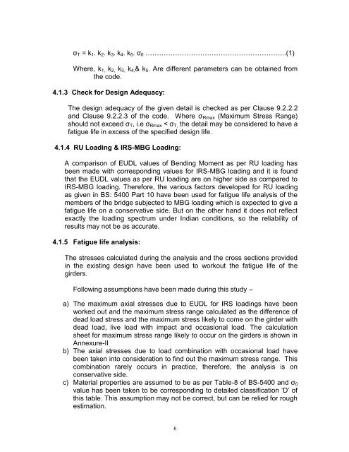
σT = k1. k2. k3. k4. k5. σ0 ……………………………………………………..(1)<br />
Where, k1, k2, k3, k4,& k5. Are different parameters can be obtained from<br />
the code.<br />
4.1.3 Check for Design Adequacy:<br />
The design adequacy of the given detail is checked as per Clause 9.2.2.2<br />
and Clause 9.2.2.3 of the code. Where σRmax (Maximum Stress Range)<br />
should not exceed σT, i.e σRmax < σT, the detail may be considered to have a<br />
fatigue life in excess of the specified design life.<br />
4.1.4 RU Loading & IRS-MBG Loading:<br />
A comparison of EUDL values of Bending Moment as per RU loading has<br />
been made with corresponding values for IRS-MBG loading and it is found<br />
that the EUDL values as per RU loading are on higher side as compared to<br />
IRS-MBG loading. Therefore, the various factors developed for RU loading<br />
as given in BS: 5400 Part 10 have been used for fatigue life analysis of the<br />
members of the bridge subjected to MBG loading which is expected to give a<br />
fatigue life on a conservative side. But on the other hand it does not reflect<br />
exactly the loading spectrum under Indian conditions, so the reliability of<br />
results may not be as accurate.<br />
4.1.5 Fatigue life analysis:<br />
The stresses calculated during the analysis and the cross sections provided<br />
in the existing design have been used to workout the fatigue life of the<br />
girders.<br />
Following assumptions have been made during this study –<br />
a) The maximum axial stresses due to EUDL for IRS loadings have been<br />
worked out and the maximum stress range calculated as the difference of<br />
dead load stress and the maximum stress likely to come on the girder with<br />
dead load, live load with impact and occasional load. The calculation<br />
sheet for maximum stress range likely to occur on the girders is shown in<br />
Annexure-II<br />
b) The axial stresses due to load combination with occasional load have<br />
been taken into consideration to find out the maximum stress range. This<br />
combination rarely occurs in practice, therefore, the analysis is on<br />
conservative side.<br />
c) Material properties are assumed to be as per Table-8 of BS-5400 and σ0<br />
value has been taken to be corresponding to detailed classification ‘D’ of<br />
this table. This assumption may not be correct, but can be relied for rough<br />
estimation.<br />
6
![Hkkjrljdkj] jsy ea= ky; vuql a/ kkuvfHkdYivkSj ekudlax Bu y ... - rdso](https://img.yumpu.com/21978459/1/184x260/hkkjrljdkj-jsy-ea-ky-vuql-a-kkuvfhkdyivksj-ekudlax-bu-y-rdso.jpg?quality=85)