RotoClamp * LinClamp * pClamp
RotoClamp * LinClamp * pClamp
RotoClamp * LinClamp * pClamp
Create successful ePaper yourself
Turn your PDF publications into a flip-book with our unique Google optimized e-Paper software.
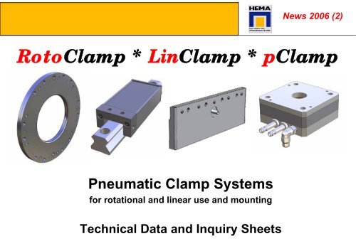
Pneumatic Clamp Systems<br />
for rotational and linear use and mounting<br />
Technical Data and Inquiry Sheets<br />
News 2006 (2)<br />
<strong>RotoClamp</strong> * <strong>LinClamp</strong> * <strong>pClamp</strong>
<strong>RotoClamp</strong> S<br />
<strong>RotoClamp</strong> – Standard sizes<br />
<strong>RotoClamp</strong> S is available in standard sizes with an internal diameter from 50 to 90 mm. Clamps with other dimensions to provide appropriate clamping<br />
performance can be developed to suit customer requirements. The required clamping performance can be increased by stacking and series connecting<br />
<strong>RotoClamp</strong> S type clamps. The application of additional pneumatic back pressure on the lamella diaphragms can be used to increase the clamping torque.<br />
The assembled thickness of the <strong>RotoClamp</strong> S is 15 mm, please consider for future designs 22 mm.<br />
Sizes Ø D1 Recommended<br />
flange diameter<br />
Ø D2 Ø D3 E F Elastic moment Elastic moment<br />
with additional<br />
air (booster)<br />
Maximum<br />
clamping<br />
moment<br />
The stated clamping moments apply with an operating pressure of 5.5 bar – 6.5 bar, clamping moment is reduced to<br />
approx. 70% of listed values for 4 bar versions. Please ask your sales consultant if your required size is available with<br />
additional air.<br />
Maximum<br />
clamping<br />
moment with<br />
additional air<br />
(booster)<br />
Tolerance +0,04 bis +0,06 -0,01 bis -0,025 ±0,1<br />
Concentricity 0.010 0.010<br />
<br />
Roughness Ra 0,8 1,6<br />
µm µm<br />
RC 50 S 50 50 134 145 63.5 67.5 60 108 100 180<br />
RC 60 S 60 60 144 155 68.5 72.5 84 153 140 255<br />
RC 70 S 70 70 154 165 73.5 77.5 114 210 190 350<br />
RC 80 S 80 80 164 175 78.5 82.5 150 270 250 450<br />
RC 90 S 90 90 174 185 83.5 87.5 189 342 315 570<br />
The friction surface of the <strong>RotoClamp</strong> is hardened and tempered (Material: Steel heat treated to 1,000 to 1,100 N/mm 2).<br />
The shaft can be supplied in any steel material, but it should be nitrided in order to guard against fretting corrosion.<br />
Product line S<br />
050 - 095<br />
<strong>RotoClamp</strong> S
<strong>RotoClamp</strong> S<br />
Product line S<br />
50 - 65<br />
<strong>RotoClamp</strong> S
<strong>RotoClamp</strong> S<br />
Product line S<br />
70 - 95<br />
<strong>RotoClamp</strong> S
<strong>RotoClamp</strong> N<br />
<strong>RotoClamp</strong> N – Standard Sizes<br />
Product line N<br />
100 - 340<br />
<strong>RotoClamp</strong> N<br />
<strong>RotoClamp</strong> N is available in standard sizes with an internal diameter from 100 to 340 mm. Clamps with other dimensions to provide appropriate clamping<br />
performance can be developed to suit customer requirements. The requisite clamping performance can be increased by stacking and multiple connecting<br />
<strong>RotoClamp</strong> N type clamps. The application of additional pneumatic back pressure on the lamella diaphragms can be used to increase the clamping torque. The<br />
assembled thickness B of the <strong>RotoClamp</strong> N is depending on the diameter and varies from 16 to 22 mm, alternative thickness in brackets.<br />
Sizes Ø D1 Recommded<br />
flange diameter<br />
Ø D2 Ø D3 B E F Elastic moment Elastic moment<br />
with additional<br />
air (booster)<br />
Maximum<br />
clamping<br />
moment<br />
Maximum<br />
clamping<br />
moment with<br />
additional air<br />
(booster)<br />
Roughness Ra 0,8 1,6<br />
µm µm<br />
Tolerance +0,04 bis +0,06 -0,01 bis -0,025 ±0,1<br />
Concentricity 0.010 0.010<br />
<br />
RC 100 N 100 100 210 228 16 (20) 103 103 240 420 400 700<br />
RC 120 N 120 120 230 248 16 (20) 113 113 336 600 560 1000<br />
RC 140 N 140 140 250 268 16 (20) 123 123 456 840 760 1400<br />
RC 160 N 160 160 270 288 16 (20) 133 133 600 1080 1000 1800<br />
RC 180 N 180 180 290 308 20 (28) 137 143 750 1380 1250 2300<br />
Tolerance +0,05 bis +0,07 -0,01 bis -0,03 ±0,1<br />
Concentricity 0.015 0.015<br />
<br />
RC 200 N 200 200 310 328 20 (28) 147 153 930 1680 1550 2800<br />
RC 220 N 220 220 330 348 20 (28) 157 163 1110 2040 1850 3400<br />
RC 240 N 240 240 350 368 20 (28) 167 173 1350 2400 2250 4000<br />
RC 260 N 260 260 370 388 22 (28) 177 183 1560 2820 2600 4700<br />
RC 280 N 280 280 390 408 22 (28) 187 193 1800 3240 3000 5400<br />
RC 300 N 300 300 410 428 22 (28) 197 203 2100 3720 3500 6200<br />
RC 320 N 320 320 430 448 22 (28) 207 213 2340 4200 3900 7000<br />
RC 340 N 340 340 450 468 22 (28) 217 223 2580 4680 4300 7800<br />
The stated clamping moments apply with an operating pressure of 5.5 bar – 6.5 bar, clamping moment is reduced to approx. 70%<br />
of listed values for 4 bar versions. Please ask your sales consultant if your required size is available with additional air.<br />
The friction surface of the <strong>RotoClamp</strong> is hardened and tempered (Material: Steel heat treated to 1,000 to 1,100 N/mm 2). The shaft<br />
can be supplied in any steel quality, but it should be nitrided in order to guard against fretting corrosion.
<strong>RotoClamp</strong> N<br />
Product line N<br />
100 - 160<br />
<strong>RotoClamp</strong> N
<strong>RotoClamp</strong> N<br />
Product line N<br />
180 - 220<br />
<strong>RotoClamp</strong> N
<strong>RotoClamp</strong> N<br />
Product line N<br />
240 - 340<br />
<strong>RotoClamp</strong> N
<strong>RotoClamp</strong> L<br />
<strong>RotoClamp</strong> – L Special sizes<br />
The stated clamping moments apply with an operating pressure of 4 bar, clamping moment without booster can be higher for 5.5<br />
bar versions. Please ask your sales consultant if your required size is available with additional air.<br />
The friction surface of the <strong>RotoClamp</strong> is hardened and tempered (Material: Steel heat treated to 1,000 to 1,100 N/mm 2). The shaft<br />
can be supplied in any steel quality, but it should be nitrided in order to guard against fretting corrosion.<br />
Options<br />
<strong>RotoClamp</strong><br />
<strong>RotoClamp</strong> L is available in listed standard sizes. Clamps with other dimensions to provide appropriate clamping performance can be<br />
developed to suit customer requirements. The requisite clamping performance can be optimally achieved by stacking and multiple connecting<br />
<strong>RotoClamp</strong> L type clamps. The application of additional pneumatic back pressure on the lamella diaphragms can be used to increase the<br />
clamping torque. The assembled thickness B of the <strong>RotoClamp</strong> L is 22 mm.<br />
Sizes Ø D1 Recommded flange<br />
diameter<br />
Ø D2 Ø D3 B E F Elastic moment Elastic moment<br />
with additional<br />
air (booster)<br />
Maximum<br />
clamping<br />
moment<br />
Maximum<br />
clamping<br />
moment with<br />
additional air<br />
(booster)<br />
Roughness Ra 0,8 1,6<br />
µm µm<br />
Tolerance +0,04 bis +0,06 -0,01 bis -0,025 ±0,1<br />
Concentricity 0.010 0.010<br />
<br />
RC 70 L 70 70 204 225 22 100 100 114 210 190 350<br />
RC 140 L 140 140 274 295 22 135 135 456 840 760 1400<br />
RC 180 L 180 180 314 335 22 155 155 750 1380 1250 2300<br />
Tolerance +0,04 bis +0,06 -0,01 bis -0,025 ±0,1<br />
Concentricity 0.010 0.010<br />
<br />
RC 200 L 200 200 334 355 22 165 165 930 1680 1550 2800<br />
RC 220 L 220 220 354 375 22 175 175 1110 2040 1850 3400<br />
RC 240 L 240 240 374 395 22 185 185 1350 2400 2250 4000<br />
RC 280 L 280 280 414 435 22 205 205 1800 3240 3000 5400<br />
RC 320 L 320 320 454 475 22 225 225 2340 4200 3900 7000<br />
RC 340 L 340 340 474 495 22 235 235 2580 4680 4300 7800
<strong>RotoClamp</strong><br />
<strong>RotoClamp</strong> – Option: shaft flange for standard sizes<br />
<strong>RotoClamp</strong> is also available as a complete unit with adapter rings according to your shaft requirements and in different materials.<br />
Options: Flanges (to be mounted on to the shaft) of<br />
following qualities:<br />
- C45 in standard version, suited for most applications<br />
-Other:ideal gliding qualities<br />
Options<br />
<strong>RotoClamp</strong><br />
Sizes Ø A Ø B<br />
n counter<br />
sink<br />
Tolerance H7 ± 0.1 mm<br />
Cylinder shape 0.015 mm<br />
100 60 80 8<br />
120 80 100 8<br />
140 100 120 8<br />
160 110 136 12<br />
180 130 156 12<br />
200 150 176 12<br />
220 170 196 12<br />
240 190 216 12<br />
260 210 236 12<br />
280 230 256 12<br />
300 250 276 12<br />
320 270 296 12
<strong>RotoClamp</strong><br />
<strong>RotoClamp</strong><br />
<strong>RotoClamp</strong> – Installation and Assembly<br />
Optional shaft ring<br />
Locating pins<br />
Shaft<br />
Ensure rigid connection for effective force transfer !<br />
Counter bore for<br />
screws according<br />
DIN 6912 / DIN 7984,<br />
Mounting taps<br />
as option<br />
RC should never be supported<br />
completely, allow area to<br />
move freely: Consider<br />
diameter D3 minus 60 mm<br />
Installation / Assembly<br />
<strong>RotoClamp</strong><br />
General:<br />
• To maximize clamping force transfer, a rigid<br />
connection to the machine structure is necessary.<br />
• Especially with large <strong>RotoClamp</strong>, from 160 mm<br />
on, clamping leads to radial expansion of the<br />
case. This expansion reduces the clamping force.<br />
• The clamping moments stated in the catalogue<br />
can only be obtained with the proper construction.<br />
We are always willing to assist.<br />
Assembly procedure shaft flange:<br />
• The shaft seat should be an g6 fitting. The shaft<br />
ring is screwed on and concentrically aligned.<br />
• Finally the remaining gap (approx. 0.1 mm) is<br />
filled with compound filler, such as Loctite 638.<br />
Assembly procedure <strong>RotoClamp</strong>:<br />
• Connect air to <strong>RotoClamp</strong>, this must be in<br />
unclamped mode. Then move it over shaft in the<br />
desired position, adjust it and tighten screws with<br />
reduced torque moment.<br />
• After you have built in the <strong>RotoClamp</strong>, reduce air<br />
pressure to 0 Bar until <strong>RotoClamp</strong> is centered<br />
fully onto shaft.<br />
• When <strong>RotoClamp</strong> is placed in the final position<br />
tighten screws fully with the defined required<br />
torque moment<br />
• Additional pins can be used.
<strong>RotoClamp</strong><br />
Technical Notes<br />
Construction<br />
Details<br />
<strong>RotoClamp</strong><br />
1. The accuracy of the clamping surfaces is<br />
obtained by internal cylindrical grinding to the<br />
given dimensions. The axial concentricity of the<br />
clamping surfaces to the bolt-on surfaces is less<br />
than 0.015 mm.<br />
2. The width of the clamping surface is approx. 7<br />
mm. Based on analysis of supporting images it<br />
can be seen that in the region between 2.5 and<br />
3 mm a high surface pressure is produced.<br />
3. The maximum bending stress on the clamping<br />
lips of the <strong>RotoClamp</strong> (without shaft) is approx.<br />
600 N/mm². The bending stress with a solid<br />
shaft is approx. 30 to 40 N/mm², with a hollow<br />
shaft, the values should lie in between. The<br />
hollow shaft must be designed to overtake the<br />
forces applied by the clamp.<br />
4. Applicable torque (example):<br />
Use of 12.9 screws M8 with a pre-tensioning<br />
force 30,700 N per screw, a friction value of<br />
µ=0,1 and Radius 100mm a transferable torque<br />
of 307 Nm per screw is achieved.<br />
5. Concentricity of the shaft when assembled<br />
should be less than 0.010 mm.<br />
6. Monitor the alignment and mounting of the<br />
clamps during procedure.<br />
7. Check the air flow in stacked clamps. Ideally<br />
stacked clamp solutions must be delivered preassembled<br />
by us. Please inform us if you intend<br />
to use this version.<br />
8. <strong>RotoClamp</strong> cannot be supported from the<br />
outside diameter.
<strong>RotoClamp</strong><br />
Warranty and how to enable long trouble-free operation<br />
1. Check mounting and installation of RC: Tightening moments,<br />
select suitable property classes of screws, make sure that the<br />
machine surface for RC is surface grinded<br />
2. The area where RC is mounted needs to have a minimum free<br />
area of 0.1 mm (D3 - 60mm), so that the RC is not supported<br />
completely.<br />
3. The locating surface for <strong>RotoClamp</strong> must be geometrically<br />
perfect, ideally surface ground.<br />
4. Consider and specify tightening moments of screws<br />
5. Respect shaft tolerances, concentricity, surface conditions,<br />
shaft and mounting area for clamp, gap tolerances between<br />
shaft and clamp<br />
6. Check and select suitable air supply , length of air hoses, type<br />
of valves<br />
7. All <strong>RotoClamp</strong> needs to be tested for life-time, precision,<br />
clamping forces and speed of clamping when usage in massproduction<br />
is considered, clamping forces and clamping<br />
behavior can change depending on the ambient influences of<br />
the system<br />
8. Specify expected number of clamping cycles per year and<br />
clamping cycle rate<br />
9. Specify the maximum required clamping force in the application,<br />
estimate the average clamping force, give the calculated safety<br />
factor to determine the ideal clamping type combination<br />
(consider 60% as safety factor), consider Elastic moment and<br />
holding forces.<br />
10. Customer machine design should support easy (de)mounting of<br />
<strong>RotoClamp</strong> and good access to allow quick and cost-effective<br />
service<br />
11. Warranty 12 months according our general terms of business<br />
and supply.<br />
Inquiry sheet<br />
<strong>RotoClamp</strong><br />
Name of company : _______________________________________<br />
Contact: _______________________________________<br />
Phone/Fax: ___________________ / ___________________<br />
E-Mail/Internet: ___________________ / ___________________<br />
Important questions for your <strong>RotoClamp</strong> – solution:<br />
Application: _______________________________________<br />
_______________________________________<br />
(Drawing of application to be attached or to be e-mailed to info@hema-schutz.de)<br />
Project partner (e.g. supplier of different construction parts): _________________<br />
Clamping cycles: ________ per year, special requirements __________<br />
Clamping torque: ________ Nm<br />
Dimensions (all specifications in mm):<br />
Outer diameter D3: ___________ Inside diameter D1: ___________<br />
Flange diameter D2: ___________ Height: ___________<br />
Standard hole positioning as shown in drawing : YES / NO<br />
For deviating options: Please send drawing or e-mail to info@hema-schutz.de)<br />
Optional adapter ring of _____________<br />
Number of pieces: ______________ Delivery date: _______________<br />
Additional data:<br />
Visit is needed / We wish a return call for further information __________________
<strong>LinClamp</strong> S<br />
Standard sizes<br />
Linear Rail Version<br />
Rail sizes<br />
20<br />
25<br />
30<br />
35<br />
45<br />
55<br />
65<br />
Technical data:<br />
L<br />
97.5<br />
117.5<br />
126.5<br />
156.5<br />
176.5<br />
202.5<br />
259.5<br />
Technical data<br />
<strong>LinClamp</strong> S <strong>LinClamp</strong> S<br />
B<br />
43<br />
47<br />
59<br />
69<br />
80<br />
98<br />
120<br />
H<br />
High<br />
Carriage<br />
30<br />
40<br />
45<br />
55<br />
70<br />
80<br />
100<br />
H1<br />
29<br />
32.5<br />
42<br />
52<br />
59<br />
74<br />
A<br />
19.5<br />
20<br />
29.5<br />
36.5<br />
38<br />
48<br />
H<br />
Large<br />
Carriage<br />
30<br />
36<br />
42<br />
48<br />
60<br />
70<br />
90<br />
H1<br />
19.5<br />
25<br />
29.5<br />
35<br />
42<br />
49<br />
64<br />
A<br />
13.5<br />
15.5<br />
17<br />
22.5<br />
26.5<br />
28<br />
38<br />
B1<br />
6<br />
6<br />
10<br />
10<br />
10<br />
12.5<br />
15<br />
C<br />
15<br />
20<br />
24<br />
24<br />
26<br />
30<br />
40<br />
G<br />
M5<br />
M5<br />
M5<br />
1/8"<br />
1/8"<br />
1/8"<br />
1/4“<br />
M<br />
M5<br />
M6<br />
M8<br />
M8<br />
M10<br />
M12<br />
M12<br />
Holding Force*<br />
900 N<br />
1.200 N<br />
1.800 N<br />
2.800 N<br />
4.000 N<br />
6.000 N<br />
10.000 N<br />
*Holding forces are valid for roller guide ways (INA, STAR) on dry rail, other conditions and rail types upon request. Consider only about 60% of listed holding<br />
forces for greasy rails depending on type of grease used. Special clamp pads with 100% holding forces (not for braking) are available for greasy rails. Clamp is<br />
released at an operating pressure of 5.5 – 6 bar, other operating pressures available on request
<strong>LinClamp</strong> SA / SK<br />
<strong>LinClamp</strong> SK (Safety Clamp)<br />
<strong>LinClamp</strong> SA (Clamps with Air)<br />
New Types<br />
<strong>LinClamp</strong> SA /SK<br />
Rail version<br />
Type Rail sizes L B H H1 A B1 C G M<br />
Holding<br />
forces*<br />
SA 25 40 75 36 23 15 5 20 M5 M6 500 N - 800 N<br />
SK 25 55,5 75 36 32,5 16 5 20 M5 M6 upon request<br />
SK 35 67 96 48 40 20 8,75 24 G 1/8 M8 upon request<br />
*Holding forces are valid for roller guide ways (INA, STAR) on dry rail, other conditions and rail types upon request. Consider only about 60% of listed holding<br />
forces for greasy rails depending on type of grease used. Special clamp pads with 100% clamping force (not for braking) are available for greasy rails. Clamp is<br />
released at an operating pressure of 5.5 – 6 bar, other operating pressures available on request
Types 25, 35 Types 35, 45 Type 25<br />
Technical Data<br />
Types<br />
25<br />
35<br />
45<br />
<strong>LinClamp</strong> A<br />
L<br />
140<br />
212<br />
262<br />
B<br />
28.15<br />
29.45<br />
29.2<br />
H<br />
60<br />
81<br />
91<br />
H1<br />
36<br />
55<br />
65<br />
*Braking forces are depending on the surface material, clamp is released at an operating pressure of 4 bar.<br />
Type 25 has a holding force of 500 N and type 35 of 800 N.<br />
A<br />
17<br />
19<br />
19<br />
C<br />
4<br />
8<br />
8<br />
D<br />
6.8<br />
6.8<br />
8.5<br />
E<br />
50<br />
50<br />
60<br />
F<br />
80<br />
150<br />
180<br />
G<br />
3.5<br />
3.5<br />
3.5<br />
I<br />
17<br />
14<br />
14<br />
J<br />
19<br />
22<br />
22.5<br />
K<br />
18<br />
18<br />
18<br />
<strong>LinClamp</strong> A
<strong>LinClamp</strong><br />
Important questions for your <strong>LinClamp</strong> – solution:<br />
Name of company: _______________________________________<br />
Contact: _______________________________________<br />
Phone/Fax: ___________________ / ___________________<br />
E-Mail/Internet: ___________________ / ___________________<br />
<strong>LinClamp</strong> Type according data table: ___________________________<br />
Number of pieces: ______________<br />
Delivery date: _______________<br />
Additional data:<br />
Visit is needed _____________<br />
We wish a return call for further information ______________<br />
Others __________________<br />
<strong>LinClamp</strong> systems can be modified for different applications.<br />
Inquiry sheet<br />
<strong>LinClamp</strong><br />
The following criteria are the basis for the individual configuration of the system.<br />
Provide as much as possible detailed and complete information:<br />
Usage horizontal vertical (with PLC) vertical (uncontrolled, free fall)<br />
System should open with air clamp with air<br />
Holding force ________ N Air pressure: ________ bar<br />
Required braking distance ____ mm Reaction time (customer system) ____ sec.<br />
Used as a) Brake b) Emergency brake c) Safety catch<br />
d) Clamp e) Operating (process) clamp<br />
Number of clamping cycles per hour : __________________<br />
Required minimum lifetime (Number of cycles) ________________<br />
Operating condition: dry oiled with grease<br />
Exact type of oil/grease : ______________________________________________<br />
Rail manufacturer, Type, Size __________________________________________<br />
Type of carriage (high/wide): ___________________________________________<br />
Other clamp types used/considered _____________________________________
<strong>pClamp</strong> N<br />
(P) Pneumatic Cylinder -<br />
(K) Piston Rod -<br />
(M) Number of Clamping<br />
Moduls A B C D Air supply E<br />
Holding<br />
force in N<br />
with 4 bar<br />
opening<br />
pressure<br />
Forces and Sizes<br />
Holding<br />
force in N<br />
with 6 bar<br />
opening<br />
pressure<br />
<strong>pClamp</strong><br />
Standard<br />
rod<br />
diameter in<br />
mm<br />
PC 63-20-1 75 56.5 8.5 39.5 M5 2.1 1400 2000 20<br />
PC 63-20-2 75 56.5 8.5 57.5 M5 2.1 2520 3600 20<br />
PC 63-20-3 75 56.5 8.5 75.5 M5 2.1 3780 5400 20<br />
PC 80-25-1 96 72 10.5 41.5 G 1/8 2.14 2100 3000 25<br />
PC 80-25-2 96 72 10,5 61.5 G 1/8 2.14 3780 5400 25<br />
PC 80-25-3 96 72 10.5 81.5 G 1/8 2.14 5670 8100 25<br />
PC 125-40-1 145 110 13 53 G 1/8 3 7000 10000 40<br />
PC 125-40-2 145 110 13 78 G 1/8 3 12600 18000 40<br />
PC 125-40-3 145 110 13 103 G 1/8 3 18900 27000 40<br />
Listed holding forces can be reached under optimal conditions, we recommend to calculate with a minimum safety factor of 10%. Please pay attention<br />
to surface conditions, material, wearing and cleanness of the rod and rod wipers which will lead to different holding forces. Please determine for safety<br />
or mass production applications the real holding force in your later application environment.
p-Clamp<br />
Inquiry sheet<br />
p-Clamp<br />
Company name: _______________________________________<br />
Contact person: _______________________________________<br />
Phone/Fax: ___________________ / ___________________<br />
E-Mail/Internet: ___________________ / ___________________<br />
PClamp-systems can be modified for different applications.<br />
The following criteria are the basis for the individual configuration of the system.<br />
Provide as much as possible detailed and complete information:<br />
PClamp-Type according data table: _______ N-Type X-Type<br />
System can only open with air, standard air pressure 4 bar 6 bar<br />
Usage horizontal vertical (with PLC) vertical (uncontrolled, free fall)<br />
Required holding force ________ N Number of modules: ____________<br />
Required holding distance ____ mm Reaction time (customer system) ____ sec.<br />
Number of clamping cycles per hour: __________________<br />
Requested minimum life cycles (Number of cycles) ________________<br />
Operating conditions: dry oil grease<br />
Exact type of oil/grease : ___________________________________<br />
Piston diameter: ________ mm<br />
Manufacturer of cylinder: ___________________________________________<br />
Description of cylinder: ____________________________________________<br />
Piston rod wiper:_ _________________________________________________<br />
Quantity: ______________ Delivery Date : _______________<br />
Visit is needed ____ We wish a return call for further information ____<br />
Others __________________________________________________________
<strong>RotoClamp</strong> * p-Clamp * <strong>LinClamp</strong><br />
Hema Maschinen- und Apparateschutz GmbH Hema Representative:<br />
Seligenstädter Strasse 82<br />
D – 63500 Seligenstadt<br />
Phone: +49-(0)6182-773-0<br />
Fax: +49-(0)6182-773-35<br />
Internet: www.hema-gmbh.com<br />
Email: info@hema-schutz.de<br />
Release: February 2006, subject to change without prior notice. Publication only with written authorisation from Hema and InnoTech.<br />
All technical data and drawings in the catalogue are standard values, which might be different in the actual customer application. Listed<br />
data are not binding, final binding values are confirmed on the actual sales order. Please pay extra care to mounting holes and<br />
assembly details.<br />
<strong>RotoClamp</strong>, p-Clamp and <strong>LinClamp</strong> are developments of InnoTech Engineering GmbH.


