Backwall Systems
Backwall Systems
Backwall Systems

You also want an ePaper? Increase the reach of your titles
YUMPU automatically turns print PDFs into web optimized ePapers that Google loves.
34<br />
<strong>Backwall</strong><br />
<strong>Systems</strong><br />
Order and request forms available at: www.hema-schutz.de<br />
<strong>Backwall</strong> <strong>Systems</strong><br />
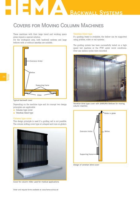
Covers for Moving Column Machines<br />
These machines with their large travel and working space<br />
areas require a special solution.<br />
For the workspace area, both backwall systems and large<br />
bellows with or without lamellas are suitable.<br />
Typical backwall cover<br />
Extension limiter<br />
Bellow<br />
Supporting frame<br />
Glider<br />
Depending on the machine type and its concept two design<br />
principles are applicable:<br />
Column type cover<br />
Venetian blind type<br />
Column type cover<br />
This design principle is used if a guiding rail is not possible.<br />
The column milling cover type is L-shaped and runs on gliders.<br />
Cover for column miller used for medical applications<br />
Venetian blind type<br />
If a guiding frame is available, the bellow can be supported<br />
using profiles, roller or rail systems.<br />
The guiding system has been successfully tested on a high<br />
speed test machine at the PTW under worst conditions.<br />
Over one million cycles were recorded.<br />
Venetian blind type cover with SAMURAI Bellows for moving<br />
column machine<br />
Extension limiter<br />
Supporting frame<br />
Design of venetian blind cover<br />
Roller or glider<br />
Bellow
CUBE <strong>Backwall</strong> <strong>Systems</strong><br />
Milling machine centres are fitted with complete backwall<br />
systems.<br />
The design of an individual solution is time and cost intensive,<br />
and these can be reduced only if larger piece<br />
numbers are produced.<br />
A modular built-up rear wall system can reduce the<br />
engineering efforts even for a single backwall - and the CUBE<br />
<strong>Backwall</strong> system was developed.<br />
Suitable for protection systems for two axes<br />
Significant reduction of engineering time<br />
Fast and detailed information for machine engineering<br />
The costs for each CUBE rear wall system are well below<br />
the costs of an individually designed concept<br />
CUBE <strong>Backwall</strong> system<br />
These features benefit machine builders with smaller<br />
production numbers and special machines.<br />
The great savings in time and money compared with<br />
previous construction requests and orders could otherwise<br />
only be managed with large production numbers of identical<br />
design.<br />
Design<br />
Using the straightforward formulas we can determine the<br />
width and the height of the outside frame of the cover and<br />
for the sheet metal design and then provide these for the<br />
machine construction. The covers in the CUBE model consist<br />
of bellows which are incorporated along the X and Y axis<br />
fitted individually for the perfect match. Depending on the<br />
loads and machine travel speeds we select suitable<br />
bellow guiding:<br />
CUBE 60: standard profiled glider guide for speeds up<br />
to 60 m/min<br />
CUBE 80: <strong>Backwall</strong> system with rail glider guide for<br />
speeds up to 80 m/min<br />
CUBE 80+: High load roller rail guide for speeds over<br />
80 m/min<br />
CUBE X: Customized solutions<br />
For backwall protection SAMURAI Bellows are used. Fixed<br />
mounted stainless steel lamellas protect the bellows against<br />
hot and sharp edged swarf.<br />
All dimensions in mm if not marked otherwise. Errors and omissions excepted.<br />
Through spindle<br />
The spindle opening is designed to the customer's requirements.<br />
The frame construction is made of solid warp resistant steel<br />
sheet. The mounting options for the rear wall can be integrated<br />
in the frame construction, but the force transmission<br />
along the X axis requires connections to the machine in the<br />
upper and lower areas.<br />
For an optimum load transmission to the X axis cover protection,<br />
this cover must be connected at the top and bottom with<br />
the moving column or other supporting machine parts.<br />
Versions of CUBE X with large extensions up to five meters<br />
long and three meters high have already been<br />
realized.<br />
Additional concepts such as DynaSynchro or pantographs<br />
can absorb the dynamic loads. Therefore a travelling speed<br />
up to 120 m/min can be realized.<br />
<strong>Backwall</strong><br />
<strong>Systems</strong><br />
35
36<br />
<strong>Backwall</strong><br />
<strong>Systems</strong><br />
CUBE <strong>Backwall</strong> <strong>Systems</strong><br />
CUBE<br />
43<br />
F x<br />
F y<br />
Calculation of spindle opening<br />
Calculation of outer frame width<br />
Order and request forms available at: www.hema-schutz.de<br />
<strong>Backwall</strong> <strong>Systems</strong><br />
V = > 80 m/min<br />
97 ZDx 75<br />
Fx 75 HUBx +ZDx 1<br />
V = 60 - 80 m/min<br />
2<br />
V = < 60 m/min<br />
3<br />
Guiding<br />
AB outer frame width<br />
(Bellow) 85<br />
43<br />
104 Huby + ZDy 72 Fy 72 ZDy U<br />
Calculation of outer frame height<br />
97<br />
AH Outer frame height
CUBE <strong>Backwall</strong> <strong>Systems</strong><br />
CUBE Guiding Application<br />
(V m/min) area<br />
CUBE 60 Standard glider guiding up to 60 m/min<br />
CUVE 80 Rail glider guiding up to 80 m/min<br />
CUBE 80+ Roller glide guiding up to 80 m/min<br />
CUBE X customized customized<br />
Design<br />
Data to be provided by customer<br />
Vx Travel speed in X direction<br />
Vy Travel speed in Y direction<br />
Hubx Required working area travel in X direction<br />
Huby Required working area travel in Y direction<br />
Fx Width of opening for spindle lead-through<br />
Fy Height of opening for spindle<br />
ZDx Required compression length X axis<br />
ZDy Required compression length Y axis<br />
AB Frame width CUBE<br />
AH Frame heigth CUBE<br />
U Fixed dimensions upper bar<br />
HEMA specification values<br />
Factors of compression<br />
CUBE 60<br />
ZD Faktor60x 0.12<br />
U60 104 mm<br />
CUBE 80<br />
ZD Faktor 80x 0.155<br />
U 80 137 mm<br />
CUBE 80+<br />
ZD Faktor 80+ 0.165<br />
U 80+ 137 mm<br />
Allgemeinfaktor Y-Achse<br />
ZDFaktory 0.075<br />
Basic principle for calculation<br />
These data also cover extreme situations. If less space is<br />
available in the customer's machine construction, the data<br />
are adapted accordingly.<br />
All dimensions in mm if not marked otherwise. Errors and omissions excepted.<br />
Calculation example<br />
Example calculation for CUBE 80+<br />
Vx 80 m/min<br />
Vy 80 m/min<br />
Hubx 800 mm<br />
Huby 650 mm<br />
Fx 200 mm<br />
Fy 200 mm<br />
Calculation of the compression<br />
ZDx = Hub x x ZDFactor80+ = 800 mm x 0.165 = [132 mm]<br />
ZDy = Hub x y ZDFy = 650 mm x 0.075 = [49 mm]<br />
[ ] = values rounded up without decimal place<br />
Calculation the results for CUBE 80+<br />
Outside frame width in X direction:<br />
AB = (System spec. value*) + Hub x + F x + 2 x ZD x<br />
AB = (97 + 75 + 75 + 97) + 800 + 200 + 2 x 132 =1.608 mm<br />
Outside frame heigth in Y direction<br />
AH = (System spec. value*) + U 80 + Hub y + F y + 2 x ZD y<br />
AH = (104 + 72 + 72) + 137 + 650 + 200 + 2 x 49 =1.333 mm<br />
*HEMA system specification values<br />
Types of spindle openings<br />
<strong>Backwall</strong><br />
<strong>Systems</strong><br />
37
38<br />
<strong>Backwall</strong><br />
<strong>Systems</strong><br />
Project team<br />
The design and realisation of large protection systems and<br />
complete backwall systems is supervised by an experienced<br />
team during all stages of manufacture.<br />
Engineering and design<br />
All important details of the machine for the design of new<br />
protection systems are integrated in the engineering stages.<br />
Every cover is individually designed to meet the specific<br />
requirements and to fit perfectly for each machine tool.<br />
Design of new protection systems<br />
Production of components<br />
All components are produced with modern machines. Sheet<br />
metal components are accurately cut to fit by laser. Other parts<br />
of the covers, such as pantographs or gliders for smooth running,<br />
are chosen individually depending on the area of application<br />
and travelling speed.<br />
During each production step all parts and materials are regularly<br />
checked for accurate dimensions and proper functioning.<br />
Visible surfaces are polished to a special finish.<br />
Test set up<br />
Before shipping all parts are checked for accurate visual<br />
appearance and perfect functionality.<br />
Functional test for prototyping<br />
Order and request forms available at: www.hema-schutz.de<br />
<strong>Backwall</strong>systems<br />
Roof cover with a length of more than nine meters, and a selfsupporting<br />
width of more than five meters<br />
<strong>Backwall</strong> system for XY-axis<br />
Shipment<br />
To be as cost efficient as possible all parts are shipped in compact<br />
and protective packaging. Customers' internal processes<br />
are given special consideration.<br />
Compact returnable shipping unit for backwall systems (optional)
CUBE <strong>Backwall</strong> <strong>Systems</strong><br />
All dimensions in mm if not marked otherwise. Errors and omissions excepted.<br />
<strong>Backwall</strong><br />
<strong>Systems</strong><br />
39