Winpact Bench-Top Fermenter Instruction Manual - Wolf Laboratories
Winpact Bench-Top Fermenter Instruction Manual - Wolf Laboratories
Winpact Bench-Top Fermenter Instruction Manual - Wolf Laboratories

Create successful ePaper yourself
Turn your PDF publications into a flip-book with our unique Google optimized e-Paper software.
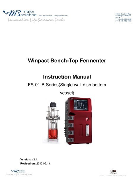
<strong>Winpact</strong> <strong>Bench</strong>-<strong>Top</strong> <strong>Fermenter</strong><br />
<strong>Instruction</strong> <strong>Manual</strong><br />
FS-01-B Series(Single wall dish bottom<br />
Version: V2.4<br />
Revised on: 2012.09.13<br />
vessel)
Table of Contents<br />
www.majorsci.com<br />
service@majorsci.com<br />
Section 1 Packing list..................................................................................<br />
.. 3<br />
Section 2 Warning.................................................................................<br />
........ 5<br />
2.2Safety Information...................................................................................<br />
. 5<br />
2.3Environmental Conditions...................................................................<br />
..... 5<br />
2.4Avoiding Electrical Shock........................................................................<br />
. 6<br />
2.5Avoiding Damage to the Instrument.......................................................<br />
.. 6<br />
2.6Equipment Operation...........................................................................<br />
.... 6<br />
Section 3 Warranty Agreements and Customer Service............................<br />
8<br />
3.1Warranty agreements.............................................................................<br />
.. 8<br />
3.2Return policy.........................................................................................<br />
... 8<br />
Section 4 Introduction................................................................................<br />
. 10<br />
Section 5 Specifications...................................................................<br />
.......... 11<br />
Section 6 Delivery & Installation..........................................................<br />
...... 28<br />
2<br />
6.1Unpacking and Parts Check...................................................................<br />
28<br />
6.2Installing the fermentation system, space requirements........................<br />
28
6.3Utility Requirements.............................................................................<br />
.. 28<br />
Section 7 Component description....................................................<br />
......... 30<br />
7.1Control unit layout..............................................................................<br />
.... 30<br />
7.2Temperature control system...................................................................<br />
36<br />
7.3Culture vessel..................................................................................<br />
...... 38<br />
Section 8 Control interface......................................................................<br />
... 38<br />
1.1Monitor................................................................................................<br />
... 39<br />
8.2Pump...................................................................................................<br />
... 40<br />
8.3Control...........................................................................................<br />
........ 42<br />
8.4Setting....................................................................................................<br />
43<br />
8.5Chart.................................................................................................<br />
..... 55<br />
8.6Calibration..............................................................................................<br />
56<br />
8.7Maint. ................................................................................................ ..... 58<br />
8.8Help.....................................................................................................<br />
... 59<br />
Section 1 Operating the system..............................................................<br />
... 60<br />
1.1Preparation and connection of the control unit.......................................<br />
60<br />
9.2Prepare the Culture Vessel and Accessories.........................................<br />
61<br />
9.3Prepare the Fermentation Run...............................................................<br />
63<br />
Section 10 Remote control setting<br />
........................................................... 66<br />
3
10.1Connecting your PC to the <strong>Winpact</strong> controller.....................................<br />
66<br />
10.2Controlling the <strong>Winpact</strong> system on your PC.........................................<br />
68<br />
Section 11 Cleaning and Maintenance.......................................................<br />
72<br />
4<br />
11.1Vessel Cleaning.................................................................................<br />
... 72<br />
11.2Control Station Cleaning.............................................................<br />
......... 72<br />
11.3DO electrode information and maintenance<br />
11.4pH probe information and maintenance<br />
........................................ 72<br />
.............................................. 73
Section 1 Packing list<br />
When the unit arrives, please make sure that all items are included in the<br />
package. Use the following packing list to check the items. If an item is<br />
missing, please contact local major science representative or<br />
service@majorsci.com<br />
Item Description Qty<br />
1 Controller 1<br />
2 Culture vessel (Single wall dish bottom) 1<br />
DO/pH probe adaptor 2<br />
10mm blind Stopper (Only for 5L, 7L, 10L vessel) 3<br />
3 Brushless motor 1<br />
Accessories<br />
4 pH probe (225mm for 3L; 325mm for 5L,7L,10L) 1<br />
5 pH probe cable 1<br />
6 DO probe (220mm for 3L; 320mm for 5L,7L,10) 1<br />
7 DO probe cable 1<br />
8 Temp. probe 1<br />
9 PT-100 Temp. probe cable 1<br />
5
6<br />
10 Antifoam probe cable 1<br />
11 Power cord (EU x1, US x1) 1<br />
12 <strong>Winpact</strong> instruction manual 1<br />
Start-up kit<br />
13 250 ml glass bottle (includes 2 ports Stainless Steel<br />
Connecting set)<br />
14 500 ml glass bottle (includes 2 ports Stainless Steel<br />
Connecting set)<br />
15 45 mm 0.2mm Autoclavable disc type air filter , 10 each/pk 1<br />
16 Stainless Steel Connecting Tube, 15 ea/pk 1<br />
17 Handy Burner 1<br />
18 Silicon tubing Clamp, 12 ea/pk 1<br />
19 #16 (inner diameter 3.2mm) silicon tube 25 ft 1<br />
20 2mm Hex Wrench 1<br />
21 12mm and 14mm Double Open-End Wrench 1<br />
22 Philips (+) Screwdriver 1<br />
4<br />
1
Signed by:<br />
Date:<br />
<strong>Winpact</strong> is liable for all missing or damaged parts / accessories within 7<br />
days after customer received this instrument package. Please contact<br />
Major Science immediately regarding this issue. If no response within<br />
such time period from consignee party, that will be consignee party’s<br />
whole responsibility.<br />
7
Section 2 Warning<br />
This equipment has been tested and verified to comply with safety limits.<br />
These limits are designed to provide reasonable protection against harmful<br />
interference when the equipment is operated in a commercial environment.<br />
This equipment may generate, use, and radiate radio frequency energy, and if<br />
not installed and used in accordance with the instruction manual, may cause<br />
harmful interference with radio communications. Operation of this equipment<br />
in a residential area is likely to cause harmful interference in which case the<br />
user will be required to correct the interference at their expense. Changes or<br />
modifications not expressly approved by the party responsible for compliance<br />
could void the users authority to operate the equipment. It is strongly<br />
recommended that the user carefully read the following prints before<br />
operating any equipment.<br />
8
1.A.A.1. Read and follow the manual instructions<br />
thoroughly.<br />
1.A.A.2. Do not alter the equipment. Failure to adhere to<br />
these directions could result in personal and/or laboratory<br />
hazards, as well as invalidate equipment warranty.<br />
1.A.A.3. Use a properly grounded electrical outlet of correct<br />
voltage and current handling capacity.<br />
1.A.A.4. Disconnect from power supply before maintenance<br />
and servicing. Refer servicing to qualified personnel.<br />
1.A.A.5. In the event that solution is accidentally spilled into<br />
the instrument, disconnect grounded plug and the user<br />
must carry out appropriate decontamination. Replace<br />
damaged parts.<br />
1.A.A.6. Do not use in the presence of flammable or<br />
combustible material; fire or explosion may result. This<br />
device contains components that can ignite such<br />
materials.<br />
1.A.A.7. Refer maintenance and servicing to qualified<br />
personnel.<br />
1.A.A.8. Ensure that the system is connected to electrical<br />
service according to local and national electrical codes.<br />
Failure to properly connect may create a fire or shock<br />
hazard.<br />
1.A.A.9. Ensure the use of appropriate materials and correct<br />
operation to avoid possible hazards of explosion,<br />
implosion or release of toxic or flammable gases arising<br />
from the heated materials.<br />
9
1.A.A.10. Handle the culture vessel with cares to prevent any<br />
damages or crashes to the glass vessel, especially before<br />
and after autoclave / sterilization.<br />
1.A.A.11. Always use the supplied handle or appropriate<br />
protection to handle culture vessel in order to prevent<br />
against heat burning your hands, especially after<br />
autoclave/sterilization.<br />
ATTENTION: Hot surface!<br />
2.2 Safety Information<br />
Use high levels of precaution when using any electrical device. Before<br />
connecting the electric supply, check to see if the supply voltage is within the<br />
range stated on the rating label, and see to it that the device be seated firmly.<br />
Place the unit in a safe and dry location, it MUST NOT touch any surrounding<br />
objects. Follow the safety precautions for chemicals/dangerous materials, and<br />
hot surfaces (after autoclave/sterilization). If needed, contact a qualified<br />
service representative or service@majorsci.com.<br />
2.3 Environmental Conditions<br />
Ensure the instrument is installed and operated strictly under the following<br />
conditions:<br />
10
3.A.A.1. Indoor use only<br />
3.A.A.2. 95% RH<br />
3.A.A.3. 75 kPa 106 kPa<br />
3.A.A.4. Altitude must not exceed 2000 meters<br />
3.A.A.5. Ambient to 40°C operating temperature<br />
3.A.A.6. Pollution degree: 2<br />
3.A.A.7. Mains supply voltage fluctuations up to ±10% of the<br />
normal voltage<br />
2.4 Avoiding Electrical Shock<br />
Follow the guidelines below to ensure safe operation of the unit.<br />
The <strong>Bench</strong> <strong>Top</strong> Programmable Fermentation System has been designed for<br />
use with shielded wires thus minimizing any potential shock hazard to the<br />
user. Major Science recommends against the use of unshielded wires.<br />
11
12<br />
1.A.A.1. Dry out for a period of time and restored to<br />
NORMAL CONDITION before operation.<br />
4.A.A.1. NEVER connect or disconnect wires leading from<br />
the power jacks when the red indicator light on the<br />
Start/Stop key is on or when RUNNING is displayed on<br />
the screen.<br />
4.A.A.2. WAIT at least 5 seconds after stopping a run before<br />
handling output leads or connected apparatus.<br />
4.A.A.3. ALWAYS make sure that your hands, work area,<br />
and instruments are clean and dry before making any<br />
connections or operating the power supply.<br />
4.A.A.4. ONLY connect the power cord to a properly<br />
grounded AC outlet.
2.5 Avoiding Damage to the Instrument<br />
5.A.A.1. Do not attempt to operate the device if damaged.<br />
5.A.A.2. Protect this unit from physical damage, corrosive<br />
agents and extreme temperatures (direct sunlight etc).<br />
5.A.A.3. For proper ventilation, leave at least 10 cm of<br />
space behind the instrument, and at least 5 cm of space<br />
on each side.<br />
5.A.A.4. Do not operate the instrument in high humidity<br />
environments (> 95%), or where condensation may occur.<br />
5.A.A.5. Before using any cleaning or decontamination<br />
method except those recommended by the manufacturer,<br />
users should check with the manufacturer that the<br />
proposed method will not damage the equipment.<br />
2.6 Equipment Operation<br />
6.A.A.1. Check that the culture and all the accessories are<br />
assembled well and not damaged before starting the<br />
autoclave and fermentation process.<br />
6.A.A.2. Ensure all other associated instruments and<br />
equipment, such as the Autoclave and Cooling Water<br />
Bath are in normal condition and their specifications meet<br />
the fermentation process needs. These instruments and<br />
equipment must be operated according to their instruction<br />
manual. Furthermore, the assembly and connection<br />
between themselves and the fermentation system must<br />
be carried out correctly.<br />
6.A.A.3. NEVER access any HAZARDOUS LIVE parts that<br />
violate International Biosafety Regulations.<br />
13
6.A.A.4. When operating other fermentation systemassociated<br />
instruments, use the same level of precaution<br />
to prevent potential damage and ensure the fermentation<br />
performance.<br />
The symbols used on the <strong>Bench</strong> <strong>Top</strong> Programmable Fermentation<br />
System are explained below.<br />
14<br />
Indicates an area where a potential shock hazard may<br />
exist.<br />
Indicates a warning. Consult the manual to avoid<br />
possible personal injury or instrument damage.<br />
ATTENTION: Hot surface!
Section 3 Warranty Agreements and<br />
Customer Service<br />
3.1 Warranty agreements<br />
Major Science warrants its products against defects in materials and<br />
workmanship, under normal service, for a period of 12 months from the<br />
shipping date to purchaser, unless other terms are agreed upon in writing.<br />
The date of reference is the date of the delivery, which must be evidenced by<br />
presenting the corresponding delivery confirmation.<br />
The guarantee is given against defects in manufacture and against<br />
malfunctioning, but not for parts subject to wear and tear (O-ring, seals,<br />
membrane filter), defects or damages caused by improper handling, or<br />
defects and malfunctions caused by corrosion (due to lack of resistance<br />
against solvents, etc., which are used for fermentation).<br />
The warranty does not cover parts subject to wear and tear or damages<br />
caused by improper handling. In addition, it does not cover the following:<br />
15
1.A.A.1. Corrosion/damage to the tubing clamps on the<br />
peristaltic pump, which is caused by contact with strong<br />
acid/base or chemicals<br />
1.A.A.2. Damage to the fermenter controller, vessel and<br />
cables caused by negligence during installation or<br />
adjustment<br />
1.A.A.3. All probes (pH, DO; excluding DO probe<br />
membrane) are covered by the warranty for six months<br />
starting from date of completion of installation<br />
1.A.A.4. O-rings, mechanical seals and start-up kits<br />
components (silicone tubing, clamp, feeding bottles, etc.)<br />
1.A.A.5. All glass parts are excluded from the warranty<br />
Note: Before first use or use under specific environmental<br />
conditions in the laboratory and/or together with special<br />
nutrients or additional solutions, you must test the resistance of<br />
all parts.<br />
Major Sciences obligation under this warranty is limited to repairing parts or<br />
providing replacement parts at no charge, which prove to be defective during<br />
the warranty period. A part shall be considered defective after inspection of<br />
Major Sciences technical staff. At Major Sciences option, we will repair or<br />
replace any defective part, which is returned to our facilities. The cost of<br />
shipping the repaired or replacement part will be borne by Major Science. Any<br />
unit where repair or modification has been performed by anyone other than<br />
Major Science or an appointed distributor/representative is no longer under<br />
warranty from the time the unit was modified.<br />
3.2 Return policy<br />
A local Major Science representative can repair defects and damages.<br />
Defective appliances can also be returned to a local Major Science<br />
16
epresentative. It will be the customers liability to pay all carriage charges.<br />
The repairs will be carried out and charged in accordance with our terms of<br />
maintenance.<br />
Note: Upon return, the equipment must be clean, in good<br />
hygienic condition and carefully packed. Contagious parts must<br />
be disinfected or sterilized, according to chemical, biological,<br />
biotechnological or genetic safety regulations. The sender has to<br />
prove compliance with corresponding safety regulations. The<br />
sender will be charged for repair or damages due to transport<br />
and for necessary cleaning and disinfection of any parts.<br />
For returning any equipment, please notify your local major science<br />
representative or contact Major Science directly:<br />
No. 37, Wuquan 5th Rd., Wugu Dist., New Taipei City 24888 Taiwan, R.O.C.<br />
TEL: 886-2-2298-1055<br />
FAX: 886-2-2299-7871<br />
19959 Sea Gull Way, Saratoga, CA 95070, U.S.A.<br />
TEL:1-408-366-9866<br />
FAX:1-408-446-1107<br />
E-mail: service@majorsci.com<br />
17
Section 4 Introduction<br />
<strong>Winpact</strong> Scientific is a product brand under Major Science, an innovative,<br />
R&D-based<br />
manufacturer supplying a broad product portfolio to the life science market.<br />
<strong>Winpact</strong> provides a comprehensive and innovative line of cultivation products<br />
designed for different cell culture experiments and applications. It comes in a<br />
benchtop scale and has a large, color touch-screen panel with a user-friendly<br />
interface. Its distinctive functions include various programming operations to<br />
control the pump speed, pH levels, temperature, and more. <strong>Winpact</strong><br />
Fermentation System is equipped with a full connection device to connect to<br />
any PC for real-time recording and control within the vessel<br />
Features<br />
18<br />
-104 color touch screen & graphical user interface<br />
-Ethernet remote control and data logging function<br />
-Flexible optional device selections<br />
-Storage program: Up to 59,994 programs for different kind<br />
of conditions<br />
-Data storage: Up to 100 data files<br />
-Data export interface: USB port<br />
-Modular system for easy upgrade & maintenance<br />
-Full accessory as a package
Section 5 Specifications<br />
Vessel Max.<br />
Working<br />
volume<br />
Total<br />
volume(Liter<br />
)<br />
Inner<br />
diameter(m<br />
m)<br />
Inner<br />
height(mm)<br />
Overall<br />
diameter(m<br />
m)<br />
Height without<br />
condenser(mm)<br />
Height with<br />
condenser(mm)<br />
Single wall (Dish bottom)<br />
3L 5L 7L 10L<br />
3.8 6.8 8.9 12.5<br />
130 160 180 190<br />
310 365 370 430<br />
200 230 250 270<br />
520 570 580 630<br />
640 640 650 700<br />
Material Borosilicate glass / 316L stainless steel for<br />
headplate and all fittings<br />
19
Control unit Control panel 10.4 Color Touch-screen Interface<br />
20<br />
Aeration Inlet Gas<br />
Temperatur<br />
e<br />
(Resolution: 800 x 600 pixels)<br />
Communication port Remote control through Ethernet<br />
Storage program Up to 59,994 programs for different kinds<br />
of condition<br />
Data storage Up to 100 data files<br />
Data storage<br />
interface<br />
USB port<br />
Cabinet material ABS front panel and painted iron housing<br />
Dimension Footprint: 400 x 500 mm (W x D) ; Height:<br />
740 mm<br />
Rated voltage 110V or 220V ; 50/60 Hz<br />
Flow-meter<br />
0, 1 10<br />
LPM<br />
Sparger Orifice ring<br />
0, 2 20 LPM<br />
Baffle Removable 316L stainless steel baffles<br />
Heating Built-in heat exchanger<br />
Cooling Cooling coil valve<br />
Range 5 ℃ above coolant up to 60℃<br />
Probe Platinum RTD probe (Pt-100)<br />
Control mode Programmable 15 steps PID controller
Agitation Drive Removable <strong>Top</strong> brushless motor<br />
Speed Range 30 1200 rpm (3L~7L) ; 30-1000rpm<br />
(10L)<br />
Impeller Three adjustable Rushton-type impellers<br />
(standard);<br />
Two Pitched-blade impellers (optional)<br />
Control mode Programmable 15 steps PID controller<br />
pH Range 2 -14 pH<br />
Probe Gel-filled electrode; Autoclavable<br />
Control mode PID, one point control with adjustable<br />
deadband<br />
DO Range 0 200%<br />
ORP(Option<br />
al)<br />
Probe Polarographic DO sensor; Autoclavable<br />
Control mode PID; Cascade function to response to<br />
Transmitter -/+ 2000 mV<br />
Resolution 1 mV<br />
a. Increase or decrease agitation speed<br />
b. Oxygen Enrichment module (Optional)<br />
c. Gas Mixing Station module (Optional)<br />
Start substrate feeding program<br />
Probe Gel-filled electrode; Autoclavable<br />
Foam Probe 316L stainless steel detector with<br />
insulated teflon tube; On/Off control<br />
21
Peristaltic<br />
pump<br />
Pump number Four built-in pumps; One external pump<br />
(Optional)<br />
Motor type Precise stepping motor; minimum speed<br />
is 1 rpm<br />
Speed range 0 65 rpm<br />
Control mode Programmable 15 steps feeding control;<br />
Pump can be assigned for Acid, Base,<br />
Antifoam and Substrate<br />
Exhaust Device type 316L Stainless steel condenser<br />
Utility<br />
requirement<br />
22<br />
Power supply 100-120V 50/60 Hz or 210-230V 50/60 Hz<br />
with electrical safety cutoff switch<br />
Water 2 Bar maximum (29 psi)<br />
Air 1 Bar maximum, must be dry, oil-free and<br />
filtered<br />
Autoclave For sterilization
Section 6 Delivery & Installation<br />
6.1 Unpacking and Parts Check<br />
Please pay attention to the following advice:<br />
1.A.A.1. Carefully check the outer packaging, the packaging<br />
of the single components, as well as the parts themselves<br />
for damage.<br />
Warning: Do not use culture vessel when damage is suspected.<br />
In such a case, the glass vessel might burst during sterilization<br />
in the autoclave.<br />
1.A.A.2. Check if the delivery is complete. To prevent<br />
scratching, please handle with care when using sharp<br />
objects to unwrap the packaging.<br />
1.A.A.3. Please use caution when loading or unloading to<br />
prevent damage due to collision.<br />
1.A.A.4. When moving or positioning the controller, take<br />
care not to lift it by holding the peristaltic pump heads.<br />
They are not designed to be used as handles, and can be<br />
damaged by lifting a heavy load.<br />
1.A.A.5. If parts are missing or damage occurs in transit,<br />
please inform your local Major Science representative.<br />
23
24<br />
6.2 Installing the fermentation system, space requirements<br />
2.A.A.1. The system will require an area of approximately W<br />
x D = 1,500 x 600 mm (including the space for the culture<br />
vessel and the cooling circulating water bath)<br />
2.A.A.2. You may vary the arrangement of the components<br />
according to the lengths of the connecting lines. It is<br />
recommended to consider some additional space for<br />
convenient handling of the equipment.<br />
2.A.A.3. Use the (+) Screwdriver to open the back panel for<br />
gas pressure adjustment before first use (Screwdriver is<br />
provided in the standard package). Detailed instructions<br />
are given below.<br />
6.3 Utility Requirements<br />
3.A.A.1. Gas Source: the incoming gas must be reduced to<br />
at least 2 bar (29psi) before entering the air inlet (Fig. 1).<br />
If you are using an air compressor or a cylinder, please be<br />
sure to use an external regulator to reduce the gas<br />
pressure. The inlet gas must be further adjusted to 0.5 bar<br />
(approx. 7psi) using the built-in pressure gauge (Fig. 2),<br />
the back panel must be opened for access). The built-in<br />
pressure gauge will be fully shut off when the<br />
fermentation system first arrives, which means no air flow<br />
will be observed in the rotameter. Open the back panel<br />
and lift up the pressure gauge knob to adjust. Turn<br />
counterclockwise to open the pressure valve and turn<br />
clockwise to close the pressure valve. After adjusting to<br />
0.5 bar, push the knob down to lock and close the back<br />
panel.
Fig. 1 Fig. 2<br />
3.A.A.2. Coolant Source: Please make sure your water<br />
quality is clean (50 micron filter). The hardness of water<br />
should be below 12 German Degree of Hardness in order<br />
to prevent calcareous deposits. The water pressure must<br />
be reduced to 1 bar (14.5psi) to prevent damage to the<br />
valve. To achieve a good cooling efficiency, we<br />
recommend setting the coolant temp. at least 15 20 º C<br />
below the desired culture temp. Using tap water is not<br />
recommended but workable. Please tighten the main<br />
water inlet connection to prevent leaking or bursting.<br />
Damage caused by impure water quality will not be<br />
covered by the warranty.<br />
Suggested tubing size for coolant & air connection (Fittings might be needed<br />
for connecting to your air & coolant source):<br />
For chiller (Main water inlet & Main water outlet port): 3/8 (9.6mm)<br />
For Air (Gas outlet, Air inlet & O2 inlet): 3/16 (4mm)<br />
25
Section 7 Component description<br />
The system is comprised of three main functional units: The Control unit, the<br />
Culture vessel, and the Heating blanket / Heating base unit. This chapter<br />
introduces the functions of each unit and gives general guidance for the<br />
machine operation.<br />
7.1 Control unit layout<br />
No. Description Function<br />
26<br />
1 10.4 color touch screen Graphical interface (Resolution: 800x600<br />
pixels)
2 Power switch ON/OFF Switch for the controller<br />
3 Air Rotameter Regulate the air flow<br />
4 Peristaltic Pump Control pH, foam level and feed nutrients<br />
5 pH probe Connect to pH probe<br />
6 ORP probe Connect to ORP sensor<br />
7 Antifoam probe Connect to antifoam sensor<br />
8 Temp. probe 2 Connect with blanket temp. probe / Measure<br />
the blanket temp.<br />
9 Vessel Temp. sensor Connect to the vessel temp. sensor (PT-100)<br />
10 GAS mixing Connect to the gas mixing station (Optional)<br />
11 Motor Connect to the brushless motor<br />
12 Base unit/Blanket Perform heating function<br />
13 DO probe Connect to the DO probe<br />
14 Condenser in Connect to the condenser inlet<br />
15 Condenser regulator Control the water flow of the condenser<br />
16 Main water in Coolant inlet<br />
17 Main water out (drain) Coolant return<br />
18 Gas out Connect to the air sparger<br />
19 Condenser out Connect to the condenser outlet<br />
27
20 Water out Connect to cooling coil (Jacket) outlet<br />
28<br />
21 Water in Cooling to cooling coil (Jacket) inlet<br />
22 O2 in Connect to the oxygen source (Optional)<br />
23 Air in Connect to the air source (External air pump or<br />
house air)<br />
24 USB port For data export<br />
25 Power socket Power supply<br />
26 Ethernet port Connect to the Ethernet and perform remote<br />
control function<br />
27 RS-485 For system expansion<br />
28 Pump 5 For external 5th pump<br />
29 AUX 1 For system expansion<br />
30 AUX 2<br />
31 O2 flowmeter (Optional) Control the oxygen flow (Only available with O2<br />
enrichment purchase)
7.2 Temperature control system<br />
2.A. Cooling system<br />
Please go to Help page to check the detailed connection instructions.<br />
No. Description Function<br />
1 Condenser in Connect to the vessel condenser inlet<br />
2 Condenser out Connect to the vessel condenser outlet<br />
3 Condenser regulator Control the water flow of the condenser<br />
4 Main water In Connect to the coolant inlet<br />
5 Main water out<br />
(Drain)<br />
Connect to the coolant return<br />
6 Water out Connect to cooling coil (Jacket) outlet<br />
7 Water in Cooling to cooling coil (Jacket) inlet<br />
29
8 O2 in Connect to the oxygen source<br />
9 Air in Connect to the air source<br />
10 Gas out Connect to air sparger port on the headplate<br />
Note:<br />
The condenser water flow is controlled by a condenser water flow regulator<br />
(See figure below). The cooling coil water flow is controlled by a solenoid<br />
valve. The solenoid valve opens only when the vessel requires cooling<br />
function. When performing temp. control, the valve will open to let water flow<br />
into the cooling coil. At the same time, you will also hear the sound of the<br />
solenoid valve, which means the valve is functioning correctly.<br />
In order to provide constant water flow through the condenser, we must turn<br />
the regulator knob to open the regulator valve halfway. The purpose is to<br />
prevent media evaporation. The condenser helps evaporated media re-<br />
condense back to liquid.<br />
30
2.B. Heating systems<br />
No. Name Description<br />
1 Coolant valve Control the coolant inlet flow<br />
2 Heat exchanger Built-in heater to provide heating function<br />
3 Circulation pump Help water circulate in the vessel<br />
31
32<br />
2.B.A.1. The minimum operating temperature in the culture<br />
vessel will be 5 ℃ above the coolant. To provide an<br />
efficient cooling control, the chiller temp. is normally set at<br />
least 10 ℃ below the culturing temperature.<br />
2.B.A.2. The water must be clean and free of particles.<br />
2.B.A.3. The hardness of water should be below 12 German<br />
Degree of Hardness in order to prevent calcareous<br />
deposits.<br />
Defects and damage caused by dirty water or calcareous<br />
deposits will not be covered by our warranty!
7.3 Culture vessel<br />
No<br />
.<br />
1<br />
2<br />
3<br />
4<br />
5<br />
3.A. Headplate Arrangement<br />
Feeding port<br />
Inoculation port<br />
To air sparger<br />
Septum port<br />
AntiFoam probe<br />
Name Function<br />
For Acid/Base/Antifoam/Substrate addition<br />
To introduce the inoculum<br />
Introduce air into the culture media<br />
Small volume sample injection<br />
Detect the foam level<br />
33
6<br />
7<br />
8<br />
9<br />
10<br />
11<br />
12<br />
13<br />
34<br />
Spare port for DO/pH probe<br />
Thermowell<br />
Cooling coil in<br />
Cooling coil out<br />
Condenser<br />
Sampling port<br />
T-hand lifter<br />
Screw nut<br />
3.B. Vessel body<br />
For installing the DO/pH probe<br />
For Pt-100 temp. probe insertion<br />
Connect to Water in port on the controller<br />
Connect to the Water out port on the<br />
controller<br />
Prevent culture media evaporation<br />
Sampling/harvesting the culture media<br />
For vessel transfer<br />
For headplate fixation
No<br />
.<br />
1<br />
2<br />
3<br />
4<br />
5<br />
6<br />
7<br />
8<br />
Glass body<br />
Headplate<br />
Supporting rods<br />
Name Function<br />
Impeller(Pitched-blade type)<br />
Sparger<br />
Baffle<br />
Condenser in port<br />
Condenser out port<br />
Made from borosilicate glass<br />
Arrange each port on the top plate<br />
Support/Protection for the vessel body<br />
Perform mixing and agitation<br />
Sparge gas into the culture vessel<br />
Disturb vortex and increase aeration<br />
efficiency<br />
Condenser coolant inlet<br />
Condenser coolant outlet<br />
Section 8 Control interface<br />
The control interface can be structured into 8 display screens depending on<br />
the functions:<br />
35
1.A.A.1. Monitor: Shows the status and readings from the<br />
sensor<br />
1.A.A.2. Pump: Controls the peristaltic pump speed and<br />
movement<br />
1.A.A.3. Control: Performs manual or automatic control of<br />
each parameter<br />
1.A.A.4. Setting: Sets up a schedule for the automatic<br />
process<br />
1.A.A.5. Chart: Plots and records the trend of a<br />
fermentation process<br />
1.A.A.6. Calibration: Performs sensor calibration<br />
1.A.A.7. Maint.: For service and maintenance only<br />
1.A.A.8. Help: <strong>Instruction</strong> for cooling system and tubing<br />
connections<br />
1.1 Monitor<br />
Once you start the system, monitor page will be shown as the first screen.<br />
Detailed descriptions are classified into nine areas (Area A - I).<br />
36
Area A: Indicates the system condition. If this area shows a green light and<br />
ON-LINE, the system is working under normal condition. If it shows a red<br />
light and OFF-LINE, there may be a problem, and you should consult with a<br />
<strong>Winpact</strong> service operator<br />
Area B: This area allows you to switch between each page<br />
Area C: Displays the readings from sensors such as DO (Dissolved oxygen),<br />
pH, Temp. and optional devices such as ORP or CO2/O2 Analyzer. Also<br />
shows the set value for your control process (SV: set value; PV: present<br />
value). If the optional device is selected, the readings will also be displayed<br />
(Ex. CO2/O2, O2 Flow)<br />
Area D: System login button. Provides access for different users<br />
Area E: Displays the condition of each device. If the device is currently<br />
operating, the color will change to flashing red<br />
Circulation pump Solenoid valve Heat exchanger<br />
37
Area F: When the system is logged in via remote control, this area will display<br />
the remote IP address<br />
Area G: Timer for process time calculation<br />
Area H: Displays the system operation mode. In this case, the screen display<br />
is MANUAL to indicate the system is operating under manual mode.<br />
Area I: This area shows the status of the fermentation process. When<br />
entering the automatic mode from the manual mode, the message will switch<br />
from the ellipsis to the running table message to indicate the automatic<br />
process.<br />
Note 1: If your system is equipped with the O2 enrichment device (optional),<br />
your monitor screen will show an additional O2 solenoid valve icon (Boxed<br />
area). You can use this to manually control oxygen flow.<br />
Note 2: Your vessel display will change according to your System Setup<br />
selection on Maintenance page (please see section 8.7)<br />
38
1.B. How to control the oxygen gas flow(Optional device)<br />
1.B.A.1. Connect your oxygen source to the O2 in port on<br />
the controller. Please go to Section 6.3 for more details.<br />
1.B.A.2. Open the controller back panel and you will find<br />
two pressure gauges (see figure below). The upper one is<br />
for oxygen, lower one is for air. Open the oxygen source<br />
and manually adjust the pressure gauge to the desired<br />
value. The pressure limit for the culture vessel 1 bar (14.5<br />
psi). If you are using a cylinder as the O2 source, please<br />
be sure to use an external regulator to reduce your inlet<br />
gas pressure (see Section 6.3).<br />
1.B.A.3. On the front panel, press the button to<br />
manually open the oxygen valve. Adjust the flow rate<br />
using the oxygen rotameter.<br />
39
40<br />
1.C. How to login to the system<br />
1.C.A.1. Please login before you start system operation<br />
1.C.A.2. Press and the login dialog will pop out<br />
1.C.A.3. Select Supervisor and key in 1234 (Default<br />
password) as the password<br />
1.C.A.4. Press OK then system will enter the monitor page<br />
1.C.A.5. To log out of the system, press<br />
Note: Users can access the system using different user names<br />
and user levels. Factory mode is for manufacturer and system<br />
maintenance purposes. The user can only choose “ Supervisor”<br />
and “ User” as the user ID. The difference between these two user<br />
ID’s will be explained in detail in Section 8.4. To change the<br />
password, also see Section 8.4.
8.2 Pump<br />
2.A.A.1. How to change the pump speed:<br />
Assign pump speed from the rpm column<br />
Peristaltic pump speed range: 1 65 rpm. Increment: 1 rpm<br />
2.A.A.2. How to change the pump direction<br />
Use and to switch the pump direction forward or backward.<br />
41
2.A.A.3. Switch between manual/automatic mode<br />
Use to switch between <strong>Manual</strong> and Automatic control.<br />
2.A.A.4. Pump 5 is for the optional external pump<br />
Four silicon tubing sizes are available. Please check the table<br />
below for the nominal flow rate.<br />
Nominal flow rate at 1 rpm (ml/min)<br />
Tube inner<br />
diameter<br />
0.8mm 1.6mm 3.2mm 4.8mm<br />
Flow rate at 1 rpm 0.06 0.21 0.8 2.8mm<br />
2.A.A.5. How to turn off the peristaltic pump<br />
In automatic mode:<br />
Go to setting page, press and enter the pump application page, choose<br />
which pump you want to switch off and switch the pump application to .<br />
This assigns the specific pump to no application.<br />
42
8.3 Control<br />
You can either manually control each parameter or run automatic control of<br />
your fermentation process<br />
Area A: Automatic mode<br />
3.A.A.1. Start an automatic fermentation process<br />
Press the button. The system will start running the process<br />
according to the Set Temperature / Stirring table and pump-feeding schedule.<br />
To set up the table and schedule, go to the Section 8.4 setting page.<br />
3.A.A.2. ACID Start function<br />
If you use the function, the automatic mode will only be<br />
43
triggered when the pH reaches the set value. To set the pH start point, go to<br />
the Section 8.4 setting page for Acid-Start setup.<br />
Note: This function is specifically designed for lactobacillus<br />
culture. The cells produce acidic metabolite as they grow and the<br />
pH drops continuously. When the pH drops to the set points, the<br />
automatic mode will activate and the whole operation turns to<br />
automatic mode by running the rpm table, Temp. table, Feeding<br />
table and controls the pH within the set range (pH Auto-setup).<br />
3.A.A.3. Stop an automatic fermentation process<br />
Press to terminate an automatic fermentation process.<br />
Area B: <strong>Manual</strong> control mode<br />
44<br />
1.A.A.1. Agitation control<br />
-Change the agitation speed from the RPM column.<br />
-Press to start manual agitation.<br />
-To stop agitation, press again.
3.A.A.4. Temperature control<br />
-Change the temp. from the temp. column<br />
.<br />
-Press to perform temp. control<br />
-Press to disable temp. control<br />
3.A.A.5. pH control parameter Setting<br />
-Change the pH value from the pH column<br />
-Press to start pH control<br />
-Press to stop pH control<br />
Note: Before using the pH control function, please assign pump<br />
applications for pumping Acid or Base. You can also define the<br />
dead-band (pH control range) and pulse interval for pumping the<br />
reagents. The detailed settings will be mentioned in Section 8.7<br />
maintenance page.<br />
45
3.A.A.6. DO Cascade<br />
-Press to start DO cascade control.<br />
-Before using the DO cascade function, go to the setting<br />
page to change the DO cascade parameters. The detailed<br />
setting will be mentioned in the next section.<br />
8.4 Setting<br />
In this page, you can program the automatic fermentation process and set up<br />
the DO cascade parameters<br />
46
4.A. Automatic Agitation Program<br />
Press to program the automatic agitation schedule.<br />
Fill in the table according to the desired settings.<br />
Note: You can set up 15 steps. In this case, the first step will run<br />
at 25 rpm for 60min., then 200rpm for next 60min, and so on.<br />
Note: To fully stop agitation under programmable mode, you will<br />
need to set two step settings. For the first step, set RPM to 0, and<br />
MIN. to 1, then on the second step, set RPM to 0 and MIN. to 0<br />
(The program stops at the previous step indefinitely, which in<br />
this case would be 0 RPM).<br />
47
4.B. Automatic Temperature Program<br />
Press to program temp. setting. The process of the temperature<br />
program is basically the same as agitation program.<br />
Note: There are 15 steps available. In this case, the temp. is kept at 50 ℃ for<br />
the first 60 mins, 60 ℃ for the next 60 mins, and so on.<br />
Note: You cannot stop temperature control fully under programmable mode.<br />
48
4.C. Peristaltic Pump setting page<br />
4.C.A.1. Press and enter the pump application page.<br />
Assign an application for each peristaltic pump. You can<br />
assign the peristaltic pump to pump Acid, Base, Antifoam<br />
or Substrate. You can also assign one to four pumps for<br />
the substrate feeding:<br />
Acid:<br />
Base:<br />
Antifoam:<br />
Substrate feeding:<br />
Note: When using CO2 gas as acid control, acid pump will be disabled.<br />
49
Example:<br />
4.C.A.2. To set up a feeding schedule, use the table above<br />
to run the specific schedule you need. You can set up the<br />
pulse interval using the table.<br />
If you need to program Feeding for continuously feeding for 2 hours, you<br />
could set the feeding pump ON for 60 seconds, OFF for 0 seconds and 120<br />
cycles in step 1; or set ON for 60 minutes, OFF for 0 minutes and 2 cycles in<br />
step 1.<br />
In this page, pump 1 is assigned for pumping Feed 1, pump 2 for Antifoam,<br />
pump 3 for Base and pump 4 for Acid. The feeding pump is set at ON for 5<br />
seconds, OFF for 2 seconds and 10 cycles in step 1. When finishing step 1,<br />
the feeding pump will start entering step 2. Up to 15 steps are available in this<br />
table.<br />
You can set up the feeding schedule based on your tubing flow rate. With this<br />
table, you can calculate how much volume can be pumped into the vessels.<br />
You can change the time unit by switching the Second/Minute button<br />
50<br />
4.C.A.3. To cancel pump applications, switch the pump<br />
application to<br />
4.D. DO cascade Setting<br />
4.D.A.1. DO (Dissolved Oxygen) Cascade<br />
Our DO cascade program is specifically designed to meet most of your<br />
experimental needs when running a fermentation/bio-reaction experiment.<br />
DO control usually does not come online until bacteria/yeast starts to grow<br />
exponentially, which consumes tremendous oxygen in a short period of<br />
time.<br />
So the purpose of the DO Cascade program is to maintain the DO level<br />
within the system once the DO set point value has dropped to a significant
level which may affect the result of the experiment. If DO level never<br />
reaches the set value, the DO cascade program will not initiate hence it<br />
will not be activated.<br />
For example, if your DO set point (SV) is set at 40% and the present value<br />
(PV) is 65%, DO cascade will not activate since PV has not dropped below<br />
40%. No action will be taken by the DO Cascade program because it has<br />
not been triggered or activated.<br />
4.D.A.2. DO Set point<br />
DO set point acts as an activator for the DO cascade program (as<br />
explained in the previous section) and also acts as a control point for your<br />
DO level.<br />
This is the set value you require for the DO level during your experiment.<br />
For example, DO level is set at 40.0%, which means when DO Cascade is<br />
triggered, it will maintain DO level at 40.0%.<br />
This setting here allows you to add substrates through your pump feeding<br />
when DO level drops below the set value (e.g. 40.0%). You could select<br />
the feeding pump you assigned on (using the pump setting). Once the<br />
feeding program is triggered, it will run to completion.<br />
4.D.A.3. Setting Menu<br />
51
The DO Cascade setting menu is located under the Setting page. Its<br />
feature can be divided into two sections: Control Strategy and Feeding<br />
Strategy.<br />
Control Strategy (1):<br />
Settings in the black box, this strategy accommodates majority of the user<br />
needs. These settings allow you to adjust DO level using Agitation, O2<br />
enrichment module, O2 with mass flow controller enrichment or Gas<br />
Mixing Station.<br />
Feeding Strategy (2):<br />
52<br />
Settings in the red box, this is commonly used for any user who wants to<br />
harvest secondary metabolites during the experiment or needs to activate<br />
a feeding program at a specific DO condition. Hence with the First Trigger<br />
and Second Trigger options, whereas Second Trigger will not activate
unless First Trigger condition has been met and is true. Details of this<br />
strategy are explained on page 7.<br />
4.D.A.4. Control Strategy<br />
After setting your DO value, lets continue to the right side of the screen,<br />
you should see there are 2 stages available for your DO control. When DO<br />
Cascade is in motion, the program will run stage 1 first, if stage 1 method<br />
fails to maintain the DO level, the system will proceed to stage 2.<br />
Selecting the right method to use:<br />
By pressing the rectangular button, you could select which specific method<br />
you prefer to run for each stage.<br />
Different Methods and related input values:<br />
b.1 Stirr<br />
Select this to use agitation to increase or decrease your DO<br />
level<br />
53
54<br />
Time (sec): duration of each cycle<br />
Step (rpm): this is the rpm value for each increment or<br />
decrement during each cycle<br />
Max (rpm): this is the maximum rpm value for this stirring<br />
method<br />
Min (rpm): this is the minimum rpm value for this stirring<br />
method<br />
b.2 Built-in O2<br />
b.3 Built-in O2<br />
b.4 O2 (GM)<br />
Select this when connecting with MS O2 enrichment module<br />
(FS-O-OE). The cycle duration will follow your O2 setting from<br />
the Maintenance page (please see page 9 for the O2 setting).<br />
All values here are irrelevant.<br />
Select this when connecting with MS Oxygen enrichment with<br />
mass flow controller (FS-O-MF)<br />
Time (sec): the calculation cycle of each time interval for the<br />
increment/decrement, sampling time<br />
Step (%): the % of the increment/decrement of the total time<br />
interval, T1 (which could be adjusted in the<br />
maintenance page)<br />
Max (%): the maximum amount of time for the solenoid<br />
valve to be opened<br />
Min (%): the minimum amount of time for the solenoid valve<br />
to be opened<br />
Select this when connecting with MS Gas Mixing Station (FS-<br />
O-GM) and would like to adjust DO level using O2 only.<br />
Time (sec): the calculation cycle of each time interval for the<br />
increment/decrement<br />
Step (%): the % of the increment/decrement of the total time<br />
interval, T1 (which could be adjusted in the
maintenance page)<br />
Max (%): the maximum amount of time for the solenoid<br />
valve to be opened<br />
Min (%): the minimum amount of time for the solenoid valve<br />
to be opened<br />
b.5 O2/N2 (GM): (FS-O-GM)<br />
Select this when connecting with MS Gas Mixing Station (FS-<br />
O-GM) and would like to adjust DO level using O2 for<br />
increasing DO and N2 for decreasing DO.<br />
Time (sec): the calculation cycle of each time interval for the<br />
increment/decrement<br />
Step (%): the % of the increment/decrement of the total time<br />
interval, T1 (which could be adjusted in the<br />
maintenance page)<br />
Max (%): the maximum amount of time for the solenoid<br />
valve to be opened<br />
Min (%): the minimum amount of time for the solenoid valve<br />
to be opened<br />
Operating procedure using Control Strategy<br />
The control strategy allows you to maintain your DO using the two<br />
methods of your choice.<br />
For the setting given above, stage 1 is using the Stirr method and stage<br />
2 is using the Built-in O2 method. Once the DO level drops below 40%,<br />
55
56<br />
DO Cascade will activate the Stirr method by increasing the agitation<br />
speed by 20 rpm per cycle. If the current setting is 200, for every 5<br />
seconds, it will increase 20 rpm to 220 rpm, and check the DO level<br />
again, if another increment is required, it will increase another 20 rpm<br />
to 240 by the next 5 seconds, and if the system reaches your set max<br />
RPM value (in this case, 500 rpm) and still unable to adjust the DO<br />
level to 40%, it will proceed to Stage 2.<br />
For Stage 2, as the example given below, this setting is using the Built-<br />
in O2 enrichment module, as previous stated, if you have purchased<br />
Gas Mixing station, Oxygen enrichment with mass flow controller, or<br />
simply the oxygen enrichment module, you need to select it<br />
appropriately in order for the setting to work properly.<br />
c.1 Flow chart of increasing DO
c.2 Flow chart of decreasing DO<br />
4.D.A.5. Feeding Strategy<br />
Once your DO level falls/reaches your set value (First Trigger value, in %),<br />
it will activate your second Trigger Value, once the DO raises up to the set<br />
value, the feeding schedule (by selecting the Feed you want) will initiate.<br />
The feeding strategy is designed for experienced user who understands<br />
his experience thoroughly and would like to schedule a feeding schedule<br />
based on the metabolic process of his bacteria such as lactobacillus. This<br />
feature allows you to add substrates feeding based on the changes of the<br />
DO level.<br />
Operating procedure using Feeding Strategy (red box)<br />
57
58<br />
As the setting given above, when the DO level drops from 40% to 20%,<br />
it will active the first trigger, which is still in idle mode but waiting for the<br />
second trigger value to be active. Once the DO level rises from 20% to<br />
50%, if a feeding schedule is selected, it will be activate.<br />
Note: if DO level rise directly from 40% to 50%, it will not activate the<br />
feeding strategy because the first trigger value (20%) was not reached.<br />
4.D.A.6. Finding your T1 (total time interval)<br />
Go to Maintenance page, on this page you should be able to locate the<br />
total time interval for the oxygen valve. (for FS-O-OE and FS-O-MF)
T1 = the cycle duration in time for the oxygen valve<br />
T2 = the duration in time the valve will open during each cycle.<br />
Note: when selecting your O2 source, these values (values in blue box<br />
from the picture below) will not apply to O2 enrichment module. Instead,<br />
Cascade will only use the pulse interval of the oxygen cycle (T1 and T2 in<br />
red box from the picture above) to adjust your DO level. All values are<br />
irrelevant.<br />
59
60<br />
Example: In the settings given below:<br />
Once the first stage of the DO cascade has failed to maintain the dissolved<br />
oxygen level, the system will automatically enters the second stage and<br />
introduce pure oxygen to raise the DO value. Make sure to have the<br />
Oxygen selection set to ON in order to have this feature to work properly.<br />
In this case, the Oxygen valve will open every 10 seconds, with increment<br />
of 1 second (10% of 10 seconds [T1] = 1 second) with maximum opening<br />
valve time as 10 seconds (100% of 10 seconds [T1] = 10 seconds) and<br />
minimum opening valve time as 1 second (10% of 10 seconds [T1] = 1<br />
second).<br />
So the system will start with opening valve for 1 second, and close for 9<br />
seconds, if it failed to maintain the DO level, it will proceed with opening<br />
valve for 2 second (1 second initial with increment of 1 second), and close<br />
for 8 seconds, and so on.<br />
For every 10 seconds (Time), the system will monitor the DO level to<br />
calculate the increment or decrement of the solenoid valve.
4.D.A.7. The Restore Delay<br />
The minimum duration in time (only in digits, not decimal points) for which<br />
the system will evaluate before it de-activate the program. (This is to make<br />
sure DO level reaches the set point and is stabilized)<br />
4.D.A.8. The Response dead-band value<br />
As our systems standard value, the response dead-band is 5 %. This<br />
value is the neutral buffer area where no action occurs. The purpose of the<br />
response dead-band value is to prevent oscillation or repeated activation-<br />
deactivation cycles of DO cascade, which may cause great fluctuation of<br />
the DO level and shorten the life of the solenoid valve. This means that if<br />
your DO set point is at 40%, the DO cascade program will not initiate and<br />
until the DO level reaches 35% (40 % - 5% [dead-band value]); vice-versa<br />
the program will sustain in the idle when the DO level reaches 45% (40% +<br />
5% [dead-band value]).<br />
Note: Response dead-band could be adjusted according to your need,<br />
61
minimum setting is 1.5 %.<br />
4.E. File Management<br />
We use different parameters for different growth conditions. To save and<br />
manage these files, you can use the New/Open/Copy/Rename/Delete<br />
function.<br />
62<br />
4.E.A.1. Open a new file: Press the New button then the<br />
following dialog will show up. Choose a file name title<br />
(LAB1 ~ LAB5) and key in a number (0001 ~ 9999). Then<br />
press OK to establish a new file. You can save up to<br />
59994 programs for different conditions.
4.E.A.2. Open a previously saved file: Press the Open<br />
button to open an existing file. Select the file you want to<br />
open and press OK.<br />
4.E.A.3. Copy a file: You can copy an existing file using<br />
copy function. The copied file allows you to further finetune<br />
each parameter if the growth conditions are similar.<br />
4.E.A.4. Rename a file: Rename an existing file using<br />
rename function.<br />
4.E.A.5. Delete a file: Delete saved files from the system<br />
memory.<br />
4.E.A.6. Display a file name:<br />
4.F. Acid-start setup<br />
This function is primarily used for Lactobacillus fermentation. To use this<br />
function, the user must input a pH value for Acid-Start setup, and then push<br />
the on the control page. Instead of immediately starting the<br />
automatic process, the controller will wait for the pH in the media to drop to<br />
the desired level, and then begin fermentation.<br />
63
4.G. pH-Auto start point<br />
Once the automatic process starts, the pH will be automatically controlled<br />
within this set value.<br />
4.H. Admin<br />
In this area, press the Admin button to enter account management dialog<br />
The supervisor has access to managing all the accounts. The supervisor can<br />
also change his/her or other users passwords through this page. Users have<br />
limited access to the controller. The functions that the user can use are<br />
assigned by the supervisor. The supervisor can set up a password for the<br />
remote control account.<br />
64
8.5 Chart<br />
65
66<br />
5.A.A.1. During the fermentation run, you can record the<br />
trend of the process. To record your process, go to the<br />
chart page.<br />
5.A.A.2. Press and start recording the process. The<br />
data will be saved into the built-in memory in log file<br />
format. The file will be named based on the date and time<br />
during which you record the process<br />
(Year/Month/Day/Hour/Min).<br />
5.A.A.3. If you want to stop recording a fermentation<br />
process, press the stop button to finish the recording.<br />
5.A.A.4. To read a saved file, press and select the xls<br />
file.<br />
5.A.A.5. Press to clear the chart screen<br />
5.A.A.6. Each parameter will be represented by different<br />
colors in the chart (Pump in yellow; DO in purple; pH in<br />
white; Agitation in green; Temp. in red)
5.A.A.7. You can change the scale for each parameter in<br />
the setting.<br />
67
-Sample rate: Recording frequency. For example, if the<br />
sample rate is 10 seconds, the system will collect data<br />
points every 10 seconds.<br />
-Temp.: Set the temp. display range<br />
-Rpm: Set the agitation speed display range<br />
-pH: Set the pH display range<br />
-PO2: Set the dissolved oxygen display range<br />
-ORP: Set the oxidation-reduction potential display range<br />
-CO2: Set the carbon dioxide display range<br />
-O2: Set the oxygen display range<br />
In order to help the user monitor the trend of a fermentation, we have the<br />
Long Curve and Short Curve displays. The purpose is to zoom in and<br />
zoom out of the curve. The data points of a short curve are fewer than those<br />
of a long curve.<br />
(6) X Scroll Gap: Scrolls the increments 20 units forward or backward every<br />
button.<br />
(8) X Marker: 50 stands for the X-axis coordinate displays. It goes in<br />
increments of 50 such as 0, 50, 100, 150, and so on.<br />
Data can be exported to an external disk for further analysis using the USB<br />
ports.<br />
Press Save to USB to export the files.<br />
68<br />
8.6 Calibration
6.A. DO probe calibration<br />
6.A.A.1. Press and enter the DO calibration page.<br />
6.A.A.2. Disconnect the cable from the DO probe. Press<br />
for Zero calibration.<br />
6.A.A.3. Place the probe into the vessel and connect the<br />
cable. Start the air pump and agitation to saturate the<br />
media dissolved oxygen.<br />
6.A.A.4. Press to set the DO 100% point when the<br />
sensor is fully polarized.<br />
6.A.A.5. Press to complete DO calibration.<br />
69
6.B. pH probe calibration<br />
pH calibration should be performed before sterilization.<br />
70
6.B.A.1. Press and start pH calibration<br />
6.B.A.2. Place the pH probe into the pH 7 standard solution.<br />
Wait until the pH value becomes stable, then press<br />
for Zero calibration.<br />
6.B.A.3. Clean the pH electrode with pure water, then dry it<br />
with Kimwipe tissue.<br />
6.B.A.4. Place the pH probe into the pH 4 standard solution<br />
and wait until the pH value is stabilized, and then press<br />
for Span calibration.<br />
6.B.A.5. Press to complete pH calibration.<br />
6.B.A.6. Clean the electrode again with pure water and dry<br />
it afterward. Disconnect the probe and install the probe<br />
into the vessel.<br />
6.C. Touch screen calibration: Use this function to align the<br />
screen position<br />
6.C.A.1. Press the Touch Calibration button. A green<br />
screen will appear.<br />
6.C.A.2. A flashing cross will appear in the corner for the<br />
first calibration point. Press and hold it down until the<br />
circle fills blue.<br />
6.C.A.3. Repeat with the remaining 3 points<br />
6.D. System time: Change the Year/Month/Hour/Min<br />
settings and press “ Set” to correct the system time<br />
71
8.7 Maint.<br />
This page is for mainly for manufacturer maintenance purposes and users<br />
have limited access.<br />
73
74<br />
7.A.A.1. Antifoam Detected Value: Foam level detection<br />
sensitivity can be increased/decreased by changing this<br />
value. This value has been optimized in the factory. There<br />
is no need to change the value. Default setting is 1800.<br />
7.A.A.2. Antifoam pulse interval: Settings for antifoam<br />
addition duration. T1 stands for pump on interval and T2<br />
stands for total duration.<br />
7.A.A.3. Oxygen pulse interval: If your system comes with<br />
an oxygen enrichment device(Model no.: FS-O-OE), you<br />
can set up this parameter. T1 stands for oxygen valve<br />
pulse cycle, T2 stands for on time.<br />
7.A.A.4. pH PID control: Set up the deadband (pH control<br />
range) for a pH control process. For example, if you want<br />
to control the pH between 7.2 and 6.8, set the deadband<br />
value at 0.2.
7.A.A.5. TCP/IP: Remote control internet settings (Please<br />
go to Section 10 for detailed settings)<br />
7.A.A.6. System logs: help users trace system profiles. The<br />
system log records a power failure, calibration raw data or<br />
error messages. Also, the system log records the user<br />
login time and info.<br />
-The calibration A/D value can be checked from calibration<br />
parameters dialog<br />
75
7.A.A.7. System Setup: Option to designate your controller<br />
according to your vessel model and the accessories that<br />
come with it. Choose motor 1 (M1 105 Watt) for vessels<br />
under 7 Liters, and choose motor 2 (M2 180 Watt) for 10,<br />
15 and 20 Liters. Choose DO probe type according to the<br />
probe you receive. Check the [CO2/O2 Gas Analyzer] box<br />
if you have the optional gas analyzer installed. System<br />
will automatically restart when the settings are applied.<br />
Note: After selecting and changing System Setup, the system will reboot<br />
automatically once you hit the Apply button<br />
Note: The PID value has been optimized before shipping. There is no need to<br />
change the PID settings.<br />
76
7.A.A.8. Restore cali.: This function allows you restore the<br />
factory settings. If you accidentally mess up your<br />
calibration profile, you can press this button to restore the<br />
factory settings.<br />
77
8.8 Help<br />
The help screen guides the user set up the cooling and air system after the<br />
vessel sterilization<br />
Section 9<br />
78
Section 1 Operating the system<br />
Note:<br />
79
80<br />
1.A.A.1. Cut lengths of tubing according to the distance<br />
between the connections.<br />
1.A.A.2. Bolded terms referring to the fermentation system<br />
can be found on the diagrams of the fermentation system<br />
(see Section 6 and Section 7).<br />
1.1 Preparation and connection of the control unit<br />
1.B. Examine the workplace<br />
1.B.A.1. Set up the control unit at the operating site and<br />
connect it to the required laboratory equipment:<br />
Power supply: make sure that the rated voltage is correct<br />
before plugging in the power cord.<br />
-Set up the coolant source: if you are using the chiller as the<br />
coolant source, please make sure the rated voltage is<br />
correct as well.<br />
1.B.A.2. See Section 6 for more details<br />
1.C. Set up the water circulation system<br />
1.C.A.1. Connect the coolant source (Chiller out port) to<br />
the Main water in port on the cooling system.<br />
1.C.A.2. Connect the coolant return (Chiller return port) to<br />
the Main water out (drain) port.<br />
1.C.A.3. Connect the cooling coil inlet to the Water in port<br />
and cooling coil outlet to the water out port.
1.C.A.4. Connect the condenser in to the condenser inlet<br />
and condenser out to the condenser outlet. (Please<br />
refer to the 8.8 Help and the picture on 7.2 Cooling<br />
system)<br />
81
9.2 Prepare the Culture Vessel and Accessories<br />
2.A. Check the Equipment<br />
While installing the culture vessel and fitting the probes and accessories,<br />
carefully check all parts for damage. Pay special attention to any potential<br />
cracks in the glass vessel, split in the O-rings (especially the one on the<br />
bottom of the head-plate), and any possible harm done to the seals on the<br />
rotating shaft.<br />
82<br />
Warning:
2.A.A.1. When a damaged glass vessel no longer has the<br />
bursting strength required for sterilization in the autoclave<br />
or running fermentation, it must be replaced immediately.<br />
2.A.A.2. Damage to the seal can cause contamination of the<br />
culture during the fermentation process. Seals-on<br />
accessories which are often removed and refitted should<br />
be replaced regularly.<br />
2.B. Vessel assembly and head-plate arrangements<br />
2.B.A.1. Unscrew the screws on top of the head-plate and<br />
remove the head-plate.<br />
2.B.A.2. Attach all parts (not including tubing) meant to be<br />
mounted onto the head-plate:<br />
2.B.A.3. O-ring seal: make sure the O-ring is properly fitted<br />
onto the bottom of the headplate<br />
2.B.A.4. Any port where there are no accessories part<br />
attached must be fitted with a blind port to prevent<br />
leakage.<br />
2.B.A.5. If an O-ring is damaged, it must be replaced. You<br />
may grease the O-rings (especially the one between<br />
glass vessel and headplate) with silicon grease to prevent<br />
the O-ring from deforming over time and to stop air from<br />
escaping from the vessel.<br />
2.C. Set up the air supply<br />
2.C.A.1. Attach two pieces of silicon tubing to either side of<br />
a 0.2 micron air filter (provided). Make sure the tubing<br />
lengths are long enough to reach from the controller to<br />
the vessel. Use clamps to close the tubing on each side<br />
of the filter.<br />
83
84<br />
2.C.A.2. Secure one end onto the To air sparger port on the<br />
vessel and the other onto the Gas out port on the<br />
controller<br />
2.C.A.3. With a storage bottle, connect one port with silicon<br />
tubing to the exhaust port on the top of the condenser.<br />
2.C.A.4. Connect the other port to a filter (an exhaust filter)<br />
with a short piece of silicon tubing.<br />
2.D. Set up the feeding port<br />
2.D.A.1. Fill the 250 ml storage bottles with acid, base,<br />
antifoam reagent, or nutrient.<br />
2.D.A.2. Connect them each with silicon tubing to the<br />
feeding ports on the head-plate. The tubing should be of<br />
sufficient length to allow for passage through the<br />
peristaltic pump in the control unit.<br />
2.D.A.3. If no acid/base/antifoam/nutrient is used, then use<br />
a shorter piece of silicon tubing to connect the two<br />
feeding ports in order to prevent air leakage.<br />
2.E. Media preparation<br />
2.E.A.1. Attach a piece of silicon tubing to the sampling port<br />
and clamp the other end.<br />
2.E.A.2. Adjust the height of the antifoam probe according<br />
the projected working volume. It is recommended that the<br />
user use at least 50 mm of tubing.<br />
2.E.A.3. Prepare the media and reagents.<br />
2.E.A.4. Pour the now mixed and ready-to-use media and<br />
water into the vessel.
2.F. pH calibration<br />
2.F.A.1. Connect the pH probe to the pH probe port on the<br />
controller.<br />
2.F.A.2. On the screen, select the Calibration tab and then<br />
select pH.<br />
2.F.A.3. Stick the probe into a pH 7 standard solution and<br />
wait until stable.<br />
2.F.A.4. Select Zero.<br />
2.F.A.5. Clean and dry the probe.<br />
2.F.A.6. Place the probe in pH 4 standard solution and wait<br />
until stable.<br />
2.F.A.7. Select Span Set.<br />
2.F.A.8. Press Finish then clean and dry the electrode<br />
again. (For more details in Section 8.6 calibration)<br />
2.G. DO calibration<br />
2.G.A.1. Select DO under the calibration tab.<br />
2.G.A.2. Make sure the DO probe and the DO probe port on<br />
the controller are not connected and then select Zero.<br />
2.G.A.3. Place the probe into the vessel and connect the<br />
cable.<br />
2.G.A.4. Start the air pump and agitation.<br />
2.G.A.5. Press Span Set when the sensor is fully polarized.<br />
85
86<br />
2.G.A.6. Press Finish. (For more details on 8.6 calibration)<br />
2.H. Final details<br />
2.H.A.1. Check all ports for proper connections.<br />
2.H.A.2. Secure the head-plate back onto the vessel by<br />
tightening the four or six screws.<br />
2.H.A.3. Make sure the o-ring on the bottom of the headplate<br />
is fitted well.<br />
2.H.A.4. Perform air leakage tests. If leakage happens,<br />
check again the possible leakage site.<br />
2.H.A.5. Wrap any exposed electrode part of the sensor<br />
(DO and pH) with aluminum foil to protect against the<br />
impact of steam.<br />
2.I.Sterilization of the culture vessel<br />
2.I.A.1. Take care that all open ports on the head-plate of<br />
the culture vessel are closed.<br />
2.I.A.2. Double-check that the electrode plugs are covered<br />
with aluminum foil.<br />
2.I.A.3. Completely disconnect the water circulation<br />
system.<br />
2.I.A.4. LOOSEN THE EXHAUST BOTTLE CAPS<br />
BEFORE STERILIZATION (Half-turn).<br />
2.I.A.5. Put the culture vessel with all storage and 500 ml<br />
exhaust bottle into the autoclave.
2.I.A.6. For single wall vessels, proper sterilization requires<br />
a temperature of 121°C for 40 minutes. For jacket<br />
vessels, the time required for sterilization is 60 minutes.<br />
9.3 Prepare the Fermentation Run<br />
3.A. Post-sterilization<br />
3.A.A.1. After sterilization, wear heat protective gloves and<br />
fasten the caps for all bottles immediately.<br />
3.A.A.2. After culture vessel and all bottles cool down, bring<br />
them from the autoclave to your work-place. Take caution<br />
during transportation when moving things from the<br />
autoclave to prevent the loosening of any tubing or<br />
connected assemblies.<br />
3.A.A.3. Place a piece of silicon tubing over the Air out port<br />
on the controller and insert the other end through a filter<br />
and then connect to the To air sparger port on the vessel.<br />
3.A.A.4. Connect the water in port on the controller to the<br />
cooling water in (coolant inlet) port on the vessel.<br />
3.A.A.5. Connect the water out port on the controller to the<br />
cooling water out (coolant outlet) port on the vessel.<br />
3.A.A.6. Connect the condenser in port on the controller to<br />
the condenser in port on the condenser.<br />
3.A.A.7. Connect the condenser out port on the controller to<br />
the condenser in port on the condenser (For more details<br />
on 8.6 DO calibration).<br />
3.A.A.8. Remove the protective aluminum foil from the<br />
electrode connectors.<br />
87
3.A.A.9. Connect the cable to the electrodes, including the<br />
pH probe, the pO2 probe and the foam level probe.<br />
3.A.A.10. Fill up the thermowell with water. Insert the Pt-100<br />
temperature probe.<br />
3.A.A.11. Connect the tubing from the feeding bottle to the<br />
feeding port.<br />
3.A.A.12. Place the silicon tubing through the peristaltic<br />
pump.<br />
3.B. Priming<br />
Perform priming to remove any air from the tubing:<br />
3.B.A.1. Select the Pump tab on the controller.<br />
3.B.A.2. Set the arrow to forward direction.<br />
3.B.A.3. Enter the desired rate at revolutions per minute.<br />
3.B.A.4. Press manual pumping button to perform priming<br />
(For more details on the manually adjusting the peristaltic pump options,<br />
please see section 8.2 Pump)<br />
88
3.C. Mount the motor<br />
3.C.A.1. Fit the bumper onto the stirring shaft.<br />
3.C.A.2. Locate the small notch on the motor and on the<br />
stirring shaft and place the motor onto the stirring shaft.<br />
3.C.A.3. Secure the motor by matching the latch.<br />
3.D. Cool down<br />
3.D.A.1. Make sure the condenser regulator is open<br />
halfway.<br />
3.D.A.2. Start the temperature PID control to the cool down<br />
the system (When you press the Temp. control button<br />
from the control interface, you will hear the sound of the<br />
solenoid valve. After cooling down the vessel to the<br />
working temp., wrap the heating blanket onto the culture<br />
vessel.<br />
DO NOT WRAP THE BLANKET AROUND THE VESSEL BEFORE<br />
IT HAS COOLED FROM STERILIZATION! This could result in the<br />
blanket damage (Blanket limitation: 60°C). Damage caused by<br />
mishandling will not be covered by our warranty.<br />
89
3.E. Inoculation<br />
3.E.A.1. Use silicon tubing to connect the inoculation bottle<br />
to the peristaltic pump (similar to the feeding bottle).<br />
3.E.A.2. Sterilize the feeding port and the silicon tubing. The<br />
user may apply a high temperature flame (1,200°C)<br />
toward the feeding port and silicon tubing opening for 10<br />
seconds.<br />
3.E.A.3. After proper sterilization of the feeding port,<br />
connect the silicon tubing to the feeding port.<br />
3.E.A.4. <strong>Manual</strong>ly pump the seed cells into the culture<br />
vessel. You can change the pump speed in the setup<br />
menu to achieve a higher flow rate.<br />
Note:<br />
Bore x<br />
wall<br />
90<br />
3.E.A.5. Tubing setup for the water-circulating system:<br />
Please go to the Help page to view the detailed<br />
connections.<br />
3.E.A.6. Half-turn the condenser water regulator to provide<br />
a continuous flow to the condenser<br />
3.E.A.7. Peristaltic pump<br />
-Quick and simple tube change.<br />
-Tubing is available in four sizes and five materials as<br />
follows:<br />
Autoprene Silicone Tygon Viton Prothane<br />
II
0.8mm x<br />
1.6mm<br />
1.6mm x<br />
1.6mm<br />
3.2mm x<br />
1.6mm<br />
4.8mm x<br />
1.6mm<br />
T0016 SAT 24 T0016 SLT 25<br />
T0016 SAT 07 T0016 SLT 12 T0016 TYG<br />
12<br />
T0016 SAT 08 T0016 SLT 16 T0016 TYG<br />
13<br />
T0016 SAT 01 T0016 SLT 02 T0016 TYG<br />
10<br />
T0016 VIT<br />
16<br />
T0016 VIT<br />
10<br />
T0016 VIT<br />
02<br />
T0016 PRO<br />
16<br />
T0016 PRO<br />
10<br />
T0016 PRO<br />
We provide #16 silicone tubing (3.2mm x 1.6mm) as the standard<br />
accessory. The silicone tubing is only for general purpose.<br />
Please do not use it for strong acid or base. To pump strong acid<br />
or base, please choose chemical resistant material (Viton or<br />
Tygon). Damage caused by misuse of liquids will not be covered<br />
by our warranty.<br />
91<br />
03
Section 10 Remote control setting<br />
Remote control is achievable using web browser, which is platform free.<br />
Additional installation of software is not required.<br />
10.1 Connecting your PC to the <strong>Winpact</strong> controller<br />
There are two ways to connect your PC to <strong>Winpact</strong> controller: direct<br />
connection from PC to controller, or connecting through a network<br />
1.A. Direct Connection (Controller to PC)<br />
Go to your PC, change your network settings so your network IP matches the<br />
controller IP.<br />
92<br />
1.A.A.1. Open your NETWORK Connection Setting window
1.A.A.2. Right click on Local Area Connection, and select<br />
Properties.<br />
93
94<br />
1.A.A.3. Choose TCP/IPv4 (this would differ depending on<br />
your operating system), and select Properties.
1.A.A.4. Change the IP to an IP thats in the same IP range<br />
shown on the controller. For example: default IP on the<br />
controller should be 10.0.0.166, change the IP on your PC<br />
to 10.0.0.55.<br />
1.B. Indirect Connection (Controller to Network)<br />
To connect through internet (LAN), you will have to setup the IP on the<br />
controller.<br />
Obtain a set of IP address that is within your network.<br />
Make sure that the IP you set for the controller is a FIXED IP, and that it does<br />
not conflict with any other IP that is within your network.<br />
95
Make sure to reboot the controller after changing the internet settings.<br />
No additional software is required, just make sure that JRE (Java Runtime<br />
Environment) is installed on your operating system.<br />
10.2 Controlling the <strong>Winpact</strong> system on your PC<br />
User: admin<br />
2.A.A.1. Open your web browser and key in the IP address<br />
with Port number. (Default IP is 10.0.0.166, Port: 8080)<br />
2.A.A.2. Click on Remote Control and the system will enter<br />
the login dialog. Type in the user name and password.<br />
Password: 0000 (Default password)<br />
96
2.A.A.3. Please skip the security dialog so that the login<br />
process can continue.<br />
97
2.B. Program page<br />
Monitor: The current value can be monitored from this page. The schematic<br />
diagram shows the working condition of each device. If the device is on, the<br />
color will be changed to red.<br />
98
2.C. Chart: Real-time recoding or history data reading can<br />
be done in this page. The log file can be saved into the<br />
computer disk.<br />
99
100<br />
2.D. <strong>Manual</strong> settings: In this page, you are able to perform<br />
remote control of agitation speed, temperature and pH.<br />
Press SET button to set up the parameters.
2.E. Auto settings: In this page, you can set up the<br />
schedule for the automatic fermentation process.<br />
Stirring table<br />
Temperature table<br />
101
Feeding table<br />
For security reasons, our remote control function will be disabled if a firewall<br />
exists. The remote control works fine within an intranet. If you have any<br />
problems with the internet setting, please consult your IT department.<br />
102
2.F. Exporting trend files into the USB hard drive for further<br />
analysis<br />
2.F.A.1. In the chart page, press Load File and select the<br />
file you wish to analyze.<br />
2.F.A.2. Plug the USB hard drive into USB port. Wait until<br />
the USB signal is detected, then press save to USB<br />
button to export the data.<br />
2.F.A.3. On your operating system, open the file to be<br />
analyzed.<br />
2.F.A.4. To plot the trend of a fermentation process, select<br />
the data you wish to plot. In this example, we select Time<br />
and Temp. for analysis.<br />
2.F.A.5. Use scatter plot function to plot the fermentation<br />
process (X axis: time, Y axis: Temp.).<br />
2.G. Understanding your data table<br />
103
Example (boxed in red, 2007/1/12, 01:02)<br />
Note:<br />
-Temperature: 48.7°C<br />
-Agitation speed: 299 rpm<br />
-pH: 6.61<br />
-pO2: 1%<br />
-Pump1: The pump has run for 51 seconds between<br />
2007/1/12 00:57 and 2007/1/12 01:02<br />
-Pump2 to Pump5: Off<br />
-Feed1 Total: the accumulated quantity of feeding before<br />
2007/1/12 01:02<br />
Parameter Unit<br />
Temperature Celsius ( ℃ )<br />
RPM Revolution Per Minute (RPM)<br />
pH pH<br />
PO2 Percentage (%)<br />
Pump 1 to Pump 5 Seconds (s)<br />
Feed 1 Total to Feed 5 Total Seconds (s)<br />
ORP millivolts (mV)<br />
104
CO2 Parts per million (PPM)<br />
O2 Percentage (%)<br />
105
Section 11 Cleaning and Maintenance<br />
11.1 Vessel Cleaning<br />
1.A.A.1. Fill the vessel with a mild detergent and water<br />
solution<br />
1.A.A.2. Let the solution stand for 1 hour, and then scrub<br />
thoroughly with a soft brush. A toothbrush may be used<br />
for smaller parts and hard to reach areas<br />
1.A.A.3. Drain, and rinse several times with tap water<br />
1.A.A.4. Rinse a final time with distilled water, and allow to<br />
dry<br />
11.2 Control Station Cleaning<br />
The control station can simply be cleaned by wiping with a damp cloth or<br />
towel<br />
11.3 DO electrode information and maintenance<br />
Please follow the instructions below to maintain your D.O. Probe:<br />
3.A. Cleaning the probe<br />
One effective way to remove contamination from the cathode surface is to<br />
wash it with a toothbrush and toothpaste. Then rinse with D.I. Water.<br />
3.B. D.O. sensor malfunction<br />
10 probable causes of D.O. sensor malfunction are listed below:<br />
106
3.B.A.1. Punctured membrane<br />
3.B.A.2. Torn or ripple membrane<br />
3.B.A.3. Dirty cathode<br />
3.B.A.4. Dirty or fouled anode surface<br />
3.B.A.5. Damaged O-ring<br />
3.B.A.6. Missing O-ring<br />
3.B.A.7. Damaged cathode<br />
3.B.A.8. Dirty membrane<br />
3.B.A.9. Corroded connector<br />
3.B.A.10. Electrolyte level too low<br />
Reference: Summer 1998 Broadley-James corporation<br />
3.C. Testing the D.O. Sensor membrane<br />
One simple way to test the membrane puncture is to connect the membrane<br />
cartridge with a syringe using an adapter. Monitor the bubble formation during<br />
pumping (See figure). Bubble formation may indicate leakage of the<br />
membrane.<br />
107
3.D. Membrane replacement and electrolyte refill<br />
3.D.A.1. Keep the sensor in an upright orientation, then<br />
unscrew the old membrane cap.<br />
3.D.A.2. Remove the membrane, expose the glass body in<br />
the air.<br />
3.D.A.3. Clean the tip of the glass body with a soft tissue.<br />
3.D.A.4. Gently introduce 1.5 ml DO solution into the new<br />
membrane cap.<br />
3.D.A.5. Carefully screw the new membrane cap onto the<br />
sensor shaft.<br />
How to replace the DO solution<br />
108
3.E. Membrane kit<br />
3.E.A.1. DO solution, 20ml<br />
3.E.A.2. Spare O-rings<br />
3.E.A.3. Pipette<br />
3.E.A.4. Polishing strip<br />
3.E.A.5. Membrane cartridge<br />
3.F. Storage and electrolyte replacement<br />
The DO probe can be stored in 3M Potassium Chloride solution. The DO<br />
solution is used for inner cartridge electrolyte replacement. After using the<br />
probe a few times, you can check the solution condition by nude eye (check if<br />
there is precipitation or color change). If precipitation or color change occurs,<br />
please replace with new solution.<br />
11.4 pH probe information and maintenance<br />
Please follow the instructions below for your pH electrodes maintenance:<br />
109
4.A. Cleaning the measuring electrode<br />
4.A.A.1. Remove any deposits from the membrane or<br />
diaphragm by rinsing the electrode with mild detergents.<br />
4.A.A.2. For calcium deposit, soak the electrode in a 0.1M<br />
HCl solution for a few minutes.<br />
4.A.A.3. For proteins, soak the electrode in a solution of 1%<br />
pepsin and 0.1M HCl for several hours.<br />
4.A.A.4. Inorganic coatings can be removed using<br />
commercially available glass cleaning solution (e.g.,<br />
Windex).<br />
4.A.A.5. Silver sulphide deposits, caused by the reaction of<br />
sulphides containing solution with silver chlorides in most<br />
electrodes, can be removed by soaking the electrode in a<br />
0.1 M thiourea/HCl solution until the diaphragm is totally<br />
bleached.<br />
4.A.A.6. To remove highly resistant deposits, hydrogen<br />
peroxide or sodium hypochlorite is recommended.<br />
4.A.A.7. Rinsing the electrodes in a 0.1M HCl or 0.1M<br />
NaOH solution for a few minutes may be able to remove<br />
the acid or alkaline soluble deposits.<br />
4.B. After cleaning<br />
After the cleaning process, soak the TrupH electrode in the storage solution<br />
(3M KCl) for 12 to 24 hours. Cleaning solution may penetrate the diaphragm<br />
during cleaning. It is necessary to calibrate the pH measurement after the<br />
hydration process.<br />
110
4.C. Storage of the electrode<br />
For long-term storage, immerse the pH electrode in a 3M KCl solution.<br />
4.D. Aging<br />
Aging is unavoidable. However, proper maintenance can delay the process.<br />
Typical symptoms of an aged measuring electrode includes:<br />
4.D.A.1. Increased response time<br />
4.D.A.2. Increased membrane resistance<br />
4.D.A.3. Declining slope, especially in the alkaline region<br />
4.D.A.4. Shift of the asymmetry potential (zero point shift)<br />
Lifetime of each electrode depends on the operating and handling conditions.<br />
The electrodes have a maximum operating lifespan of 18 months if handled<br />
properly. The lifetime may only last 2 months if operated at the temperatures<br />
exceeding 90°C. The electrode stops working after only 2 weeks when<br />
exposed to strong base (pH > 13) and high temperature (> 90°C).<br />
In most cases, we will find that pH electrodes age gradually. An increased<br />
response time is the most direct indication of aging. If the response time<br />
becomes unacceptable for your fermentation process control, we recommend<br />
replacing the pH electrode with a new one.<br />
4.E. Storage solution<br />
To prevent dehydration of the probe, we recommend storing the probe in the<br />
3M Potassium Chloride solution every time after use.<br />
111