00214EN Rev.05 - CytoFAST Elite - Wolf Laboratories
00214EN Rev.05 - CytoFAST Elite - Wolf Laboratories
00214EN Rev.05 - CytoFAST Elite - Wolf Laboratories

Create successful ePaper yourself
Turn your PDF publications into a flip-book with our unique Google optimized e-Paper software.
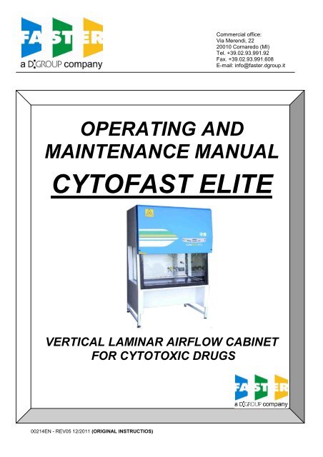
OPERATING AND<br />
<strong>00214EN</strong> - REV05 12/2011 (ORIGINAL INSTRUCTIOS)<br />
Commercial office:<br />
Via Merendi, 22<br />
20010 Cornaredo (MI)<br />
Tel. +39.02.93.991.92<br />
Fax. +39.02.93.991.608<br />
E-mail: info@faster.dgroup.it<br />
MAINTENANCE MANUAL<br />
CYTOFAST ELITE<br />
VERTICAL LAMINAR AIRFLOW CABINET<br />
FOR CYTOTOXIC DRUGS
a D:GROUP company<br />
CONTENTS<br />
1 GENERAL .................................................................................................................................................................. 2<br />
2 INSTALLATION.......................................................................................................................................................... 3<br />
2.A INSTRUCTIONS AND CHECKS ON DELIVERY ............................................................................................... 3<br />
2.B INSTALLATION REQUIREMENTS.................................................................................................................... 3<br />
2.C ELECTRIC/GAS CONNECTIONS AND INSTALLATION OF THE WORK SURFACE ......................................... 5<br />
3 OPERATION PRINCIPLES ........................................................................................................................................ 7<br />
4 OPERATION .............................................................................................................................................................. 8<br />
4.A SCOPE .............................................................................................................................................................. 8<br />
4.B CONTROL AND REGULATION SYSTEMS ....................................................................................................... 8<br />
4.C REMOTE SIGNALS (OPTIONAL) ...................................................................................................................... 9<br />
4.D INFLATABLE GASKET (OPTIONAL)................................................................................................................. 9<br />
4.E SYMBOLS OF THE CONTROL PANEL.............................................................................................................. 10<br />
4.F MANAGEMENT AND PROGRAMMING OF RESIDUAL LIFETIME ................................................................. 14<br />
4.G DISPOSAL OF WASTES AND CONTAMINATED MATERIALS....................................................................... 19<br />
4.H ERGONOMICS................................................................................................................................................ 20<br />
5 LIMITATIONS ........................................................................................................................................................... 21<br />
6 OPERATING PROCEDURES .................................................................................................................................. 22<br />
6.A PRELIMINARY CHECKS................................................................................................................................. 22<br />
6.B SWITCHING ON THE CYTOFAST ELITE CABINET ............................................................................................ 22<br />
6.C SWITCHING OFF THE CYTOFAST ELITE CABINET........................................................................................... 22<br />
7 MAINTENANCE ....................................................................................................................................................... 23<br />
7.A INSTRUCTIONS FOR DAILY CLEANING OF CYTOFAST ELITE (BY USERS) .................................................. 23<br />
7.B CLEANING OF GLASS.................................................................................................................................... 24<br />
7.C INSTRUCTIONS FOR THE FUMIGATION/STERILIZATION OF BIOLOGIC SAFETY CABINETS .................. 24<br />
7.D REPLACEMENT OF HEPA FILTERS (BY TECHNICAL ASSISTANCE PERSONNEL)................................................... 27<br />
7.E REPLACEMENT OF MOTOR-FANS (BY TECHNICAL ASSISTANCE PERSONNEL) .................................................... 32<br />
7.F REPLACEMENT OF FLUORESCENT LAMPS (BY TECHNICAL ASSISTANCE PERSONNEL)..................................... 34<br />
7.G REPLACEMENT OF U.V. GERMICIDE LAMP (BY TECHNICAL ASSISTANCE PERSONNEL)...................................... 34<br />
7.H SPARE PARTS LIST........................................................................................................................................ 35<br />
8 TROUBLESHOOTING - PROBABLE CAUSES OF MALFUNCTIONS .................................................................... 37<br />
9 MONITORING SYSTEM........................................................................................................................................... 39<br />
10 TRANSPORT, PACKING and STORAGE INSTRUCTIONS................................................................................ 40<br />
11 ADDITIONAL INFORMATION.............................................................................................................................. 43<br />
11.A GUARANTEE .................................................................................................................................................. 43<br />
11.B ADDRESS FOR TECHNICAL ASSISTANCE (FOR THE DISTRIBUTOR)................................................................ 43<br />
12 DIAGRAMS.......................................................................................................................................................... 44<br />
12.A DIAGRAM FOR MAINTENANCE OPERATIONS............................................................................................. 45<br />
12.B CYTOFAST ELITE FRONTAL AND SIDE DIAGRAM......................................................................................... 47<br />
13 ASSEMBLY of SUPPORT TABLE ....................................................................................................................... 49<br />
14 ASSEMBY OF THE CABINET ON THE SUPPORTING STAND ......................................................................... 50<br />
15 SAFE WORKING AREA DIAGRAM..................................................................................................................... 51<br />
16 SENSORS LIST................................................................................................................................................... 52<br />
17 WIRING DIAGRAM.............................................................................................................................................. 53<br />
18 DECLARATION OF CONFORMITY..................................................................................................................... 56<br />
REFERENCE STANDARD: this instruction and maintenance manual complies with the European standard en-591 (march<br />
1994) approved by CEN (European Committee for Standardization) relating to the requirements for drawing up users'<br />
instruction manuals for laboratory instruments.<br />
Note: the inobservance of the instructions of this manual can reduce the operator safety<br />
<strong>00214EN</strong> <strong>Rev.05</strong> – 12/2011 1
a D:GROUP company<br />
1 GENERAL<br />
Vertical laminar airflow benches with partial exhaust and protection barrier, the CYTOFAST ELITE cabinets,<br />
are designed to protect both the material to be manipulated from contamination and to protect the operator<br />
and the environment from microbial cytotoxic contamination hazards.<br />
The de-dusted, filtered and sterile air passing through the main HEPA filter ensures optimum airflow<br />
laminarity on the work surface, thanks to its even perforation and the frontal air barrier. The system is<br />
designed to create a protective barrier and prevent exchanges between the internal, potentially biologically<br />
contaminated air, and the outside.<br />
CYTOFAST ELITE cabinets are Class II Biohazard cabinets, according to the definitions now adopted by all<br />
the main international standards, with about 70% laminar flow recirculated air and 30% extracted air with prior<br />
HEPA filtering. Suitable for the treatment of class CDC-1/2/3, DHSS-C/B1/B2 group 1,2,3 microorganisms as<br />
per D.L. 81/08 “Safety in the working environment” and wherever a product-personnel-environment crossprotection<br />
is required.<br />
Especially suitable for applications such as:<br />
- Manipulation of eziologic agents having a known pathogenicity on humans and animals.<br />
- Presence of high concentrations of biologic materials.<br />
- Presence of agents likely to cause genetic alterations or synergetic activities with other materials.<br />
- Oncogenic viruses.<br />
But above all designed for:<br />
- Preparation and handling of cytotoxic drugs<br />
- Preparation and manipulation of antineoplastic chemotherapeutics<br />
Do not manipulate the products on the slotted part at the entry of the chamber, but in the middle of the work<br />
surface.<br />
The performances of the cabinets are detailed in the TESTING CERTIFICATE below, in compliance with the<br />
requirements of:<br />
- ISO 14644-1 Class 5<br />
For the Biohazard/Cytotoxicity:<br />
- DIN 12980: 2005<br />
- EN 12469: 2000<br />
Furthermore <strong>CytoFAST</strong> <strong>Elite</strong> cabinets fulfil the armonized standards EN 61010-1 as well as EN 61326<br />
according to the applicable European directives regarding the CE marking.<br />
<strong>CytoFAST</strong> cabinets comply with the above-mentioned standards ONLY if the instruments connected to the<br />
electrical socket positioned inside the work chamber are "CE" marked or in any case it meets the above<br />
mentioned standards aiming to avoid any electromagnetic interference.<br />
All FASTER's cabinets are provided with high insertion loss filters.<br />
Faster s.r.l. cannot be held responsible for malfunctions, damage to people or property due to noncompliance,<br />
poor or no maintenance, or improper use of the cabinet.<br />
<strong>00214EN</strong> <strong>Rev.05</strong> – 12/2011 2
a D:GROUP company<br />
2 INSTALLATION<br />
2.A INSTRUCTIONS AND CHECKS ON DELIVERY<br />
Considering the critical nature of the use of the CYTOFAST ELITE cabinet and the need to keep it in<br />
optimum condition, installation is very important.<br />
CYTOFAST ELITE Biohazard cabinets are positioned on a pallet, wrapped in an extensible film and<br />
contained in a package of multi-layer strapped cardboard.<br />
After placing the cabinet in its site of use, opened the package and removed the extensible film, check that<br />
the equipment has not suffered any dents or scratches due to transport or improper handling of the package.<br />
In case of any further transport, packing and storage by the user after the initial period of use (e.g.: change<br />
of laboratory or factory), contact the technical assistance service or the distributor for more accurate and<br />
precise instructions or for assistance by specialized technicians.<br />
2.B INSTALLATION REQUIREMENTS<br />
Install the cabinet away from drafts and heat sources (radiators, ventilators/convectors), to ensure proper<br />
functioning. For instance, in a small room (
a D:GROUP company<br />
Thimble method example<br />
LEGENDA:<br />
1. Exhaust air from the cabinet.<br />
2. Air from the environment.<br />
3. Bleed Air (100÷200 m 3 /h more than the exhaust air<br />
flow rate from the cabinet) to a dedicated exhaust<br />
fan (in the electronic board a voltage free contact is<br />
available –see electrical diagram- to check when<br />
ventilation is ON).<br />
For the connection to the gas and/or vacuum networks, read carefully chapter 2C.<br />
The quantity of heat generated by the cabinet, if the air is not extracted ouside the room, is the following for<br />
the eight models respectively:<br />
The quantity of heat generated by the cabinet, if the air is not extracted outside the room, is the following for<br />
the four models respectively:<br />
- CYTOFAST ELITE 209: 410 Kcal/h<br />
- CYTOFAST ELITE 212: 460 Kcal/h<br />
- CYTOFAST ELITE 215: 520 Kcal/h<br />
- CYTOFAST ELITE 218: 540 Kcal/h<br />
Microbiological Safety Cabinet<br />
THIMBLE<br />
The installation must be done by technicians authorized by Faster S.r.l. or by the distributor<br />
<strong>00214EN</strong> <strong>Rev.05</strong> – 12/2011 4<br />
1<br />
3<br />
2
a D:GROUP company<br />
2.C ELECTRIC/GAS CONNECTIONS and INSTALLATION OF THE WORK SURFACE<br />
The electrical connection of the <strong>CytoFAST</strong> Biohazard cabinet is made by connecting the power cable located<br />
on the upper of the right side of the cabinet to a suitable power point (see technical table) . When the cabinet<br />
is connected, the green light on the control panel switches on (see chapter 4E).<br />
If stipulated by local legislation, insert upstream of the power line an automatic protection overload switch<br />
provided with a differential relay, with a rated switching voltage no greater than 30 mA.<br />
The right side of the cabinet is also provided with two gas/vacuum intakes with manual taps one of which is<br />
fitted with an electrovalve.<br />
The connection with the two gas/vacuum intakes is made according to the type of connection: town gas or<br />
industrial gas (air, vacuum, nitrogen, etc.).<br />
The cabinet must be connected by qualified staff to the town gas mains through an approved conduit for<br />
safety reasons.;<br />
For the installation of the work surface, proceed as follows:<br />
- remove the protective paper from the work surface resting against the back of the cabinet, taking care<br />
not to scratch its surface,<br />
- open the safety front window,<br />
- clean the work surface with a damp cloth soaked in alcohol or soapy water or with a commonly available<br />
product designed for stainless steel,<br />
- place the table in the work chamber, allowing the back to slide on the chamber's supporting bases up to<br />
its bottom wall<br />
- close the safety front window<br />
Note: the plug of the supply cable of the cabinet has the function of “main switch”, therefore the<br />
operator has to access easily to it also after the installation of the cabinet.<br />
<strong>00214EN</strong> <strong>Rev.05</strong> – 12/2011 5
a D:GROUP company<br />
Techincal Features Table<br />
Description Unit <strong>CytoFAST</strong> <strong>Elite</strong> 209 <strong>CytoFAST</strong> <strong>Elite</strong> 212 <strong>CytoFAST</strong> <strong>Elite</strong> 215 <strong>CytoFAST</strong> <strong>Elite</strong> 218<br />
Overall Dimensions (L x H x P(*)) mm 1045x2345x860 1350x2345x860 1655x2345x860 1960x2345x860<br />
Usefull dimensions (L x H x P) mm 899x740x580 1194x740x580 1499x740x580 1804x740x580<br />
Maximum front aperture mm 440 440 440 440<br />
Working aperture mm 200 200 200 200<br />
Weight Kg 215 245 285 325<br />
Noise level dB (A) 1000<br />
Nitrogen, CO2, compressed air - maximum pressure bar 4 4 4 4<br />
Fuel gas- maximum pressure mbar 20 20 20 20<br />
Main voltage V 230V AC 2P+T 230V AC 2P+T 230V AC 2P+T 230V AC 2P+T<br />
Frequency Hz 50 50 50 50<br />
Maximum power consumption W 1424 1534 1681 1898<br />
Current A 7.82 8.63 9.18 9.80<br />
Electrical class 1 1 1 1<br />
Protection level IP20 IP20 IP20 IP20<br />
Internal outlet (maximum current for all the sockets: 4A) 2P+T 230V 4A 2P+T 230V 4A 2P+T 230V 4A 2P+T 230V 4A<br />
Fluorescent lamps W 2x30 2x36 2x58 2x58<br />
(*) Overall depth can be reduced to 795 mm removing the back external panel<br />
<strong>00214EN</strong> <strong>Rev.05</strong> – 12/2011 6
a D:GROUP company<br />
3 OPERATION PRINCIPLES<br />
The following are the working principles of the CYTOFAST ELITE-cabinet :<br />
the pressurized air pushed into the plenum of the main motor-fan passes through the absolute filter and then<br />
downwards, in laminar flow, into the working chamber (A). From here, through the slots of the work surface,<br />
having mixed with the external air (B) which enters the cabinet from the front opening, the air passes through<br />
the absolute filter placed under the work surface (C) and is sucked into the intake up channel situated at the<br />
rear of the working area (D). Part of the air (E) is extracted by the second motor-fan through the<br />
corresponding absolute exhaust filter. This extracted air generates the intake of air from the outside (front<br />
barrier) which ensures the protection of the operator/environment from hazardous material manipulated in the<br />
working area.<br />
The extracted air may be filtered again through a second absolute exhaust filter placed on the exhaust duct of<br />
the cabinet (BS 5726), if the air is recycled inside the laboratory where the cabinet is installed.<br />
E<br />
A<br />
C<br />
<strong>00214EN</strong> <strong>Rev.05</strong> – 12/2011 7<br />
D<br />
C<br />
E<br />
A<br />
B
a D:GROUP company<br />
4 OPERATION<br />
4.A SCOPE<br />
The vertical laminar airflow cabinet CYTOFAST ELITE is manufactured in compliance with international<br />
standards for the protection of the material, the operator and the environment against biological (Class II) and<br />
cytotoxic hazards and is suitable for the manipulation of low- and middle-risk pathogenic agents.<br />
4.B CONTROL AND REGULATION SYSTEMS<br />
The CYTOFAST ELITE cabinet is provided with an automatic regulation system to keep the airflow speed<br />
(0.4 m/sec) in the work chamber and the recycling air/extracted air ratio constant. This system counters the<br />
effects of the gradual clogging of the three HEPA filters up to pressures of nearly 35 mm H2O.<br />
The soft-touch control panel is microprocessor-controlled with a display showing all relevant data with regard<br />
to the operating functions, the different alarms and the error messages.<br />
The solid work surface creates optimal airflow laminarity at working level in the preparation of cytotoxic drugs,<br />
while the front longitudinal slots create a protective air-barrier.<br />
The vertically sliding safety glass sash is electrically operated. When the cabinet is running the work opening<br />
must be 200mm; any moving of the glass activates an audible and visual alarm, which cannot be silenced<br />
according to the EN 12469 standard.<br />
When the cabinet is off the glass can be either opened up to the maximum opening or closed completely.<br />
The front sash window can be closed and opened by pressing alternatively one of the two keys “arrow-up and<br />
arrow-down” [8] – and the red safety key on the right (see paragraph 4E)<br />
The further red key [16] is a safety measure for the operator, because the moving of the glass from the work<br />
position is possible only if this key and one of the other two keys (arrow-up and arrow-down) are pressed at<br />
the same time.<br />
When the cabinet is on, any change of the work aperture invalidates the efficiency of the air barrier<br />
protecting the operator, therefore if the operator presses the two keys at the same time he is perfectly<br />
aware of the potential risk he is running<br />
Furthermore a safety device is installed, which stops the motor-fans automatically when the cabinet is on<br />
and the electrically operated sash window is completely closed.<br />
To optimize the visibility inside the work chamber, the cabinet is ergonomically angled sloping-fronted (abt. 7<br />
degrees sloping as to the vertical)<br />
<strong>00214EN</strong> <strong>Rev.05</strong> – 12/2011 8
a D:GROUP company<br />
4.C REMOTE SIGNALS (OPTIONAL)<br />
The electronic control board can be improved adding the following optional features:<br />
Ventilation status (ON/OFF)<br />
It is possible to obtain a 12 Vdc output to connect a led light or alternatively a Normally Open voltage free<br />
contact to be connected to an external circuit.<br />
There are two different working possibilities:<br />
1 the signal starts when ventilation is turned ON and stops when ventilation is OFF.<br />
2 the signal is flashing during the start up phase of the ventilation and is ON when the correct air flow<br />
conditions are reached.<br />
Correct air flow conditions<br />
It is possible to obtain a 12 Vdc output to connect a led light or alternatively a Normally Open voltage free<br />
contact to be connected to an external circuit. That signal is closed when air flow rate is in the correct range<br />
and it is open in case of any flow alarm.<br />
External consent<br />
On request it is possible to allow ventilation to be turned ON by a remote volt free contact. When the<br />
ventilation is turned ON the cabinet stay in stand by (start up) till the remote normally open contact is closed.<br />
If during normal ventilation the remote contact is open the following message will appear “REMOTE<br />
CONTACT OFF” and the operator has to switch OFF ventilation as soon as possible and then check the<br />
reasons of the failure.<br />
4.D INFLATABLE GASKET (OPTIONAL)<br />
The optional inflatable gasket can be used to improve the sealing of the front glass during normal working<br />
phase or during the sterilization of the unit.<br />
The cabinet is supplied with a plastic pipe to be connected to compressed air line (at customer charge) or to<br />
a compressor (available as option on request).<br />
The gasket can be inflated only when the front glass is in working position or in completely closed position.<br />
To inflate and deflate the gasket the “SET” [10] and “GLASS SAFETY” [16] keys have to be pressed at the<br />
same time.<br />
Since the gasket will be pressed against the front glass, in that case it is not allowed to move the glass and<br />
the message “DEFLATE GASKET” will appear.<br />
If the gasket is deflated, after 5 seconds, a pressure sensor will allow the front glass to be moved again.<br />
In case the control panel is opened and the glass is moved, the gasket will deflate immediately if it is inflated<br />
The pneumatic circuit of the gasket is fitted with pressure switch in order to check the correct operation of it.<br />
In case of a pressure loss the alarm message “CHECK THE GASKET” will alert the operator.<br />
<strong>00214EN</strong> <strong>Rev.05</strong> – 12/2011 9
a D:GROUP company<br />
4.E SYMBOLS of the CONTROL PANEL<br />
List and description of all the symbols and controls of the control panel:<br />
12 13 14 2 15 3 4 16<br />
5 6 7 8 9 10 11 1<br />
1 MAIN SWITCH:<br />
Position "0" in the "0" position, the green light of the mains voltage is on (3); the LCD<br />
displays the model name. In this position the operator can activate only the<br />
fluorescent light (7), the U.V. lamp (14) and the power outlet (6) (with plug<br />
installed) and can activate the data stored in the microprocessor by pressing<br />
the “STATUS” key (2).<br />
Position "I" by pressing "I" the password to enter is requested. When the password is<br />
typed in (press arrow-up key (▲) 5 times, arrow-down key (▼) 4 times and<br />
press SET(10)) the green led of the switch lights up and the cabinet starts<br />
operating, LAF and exhaust (if installed) motor-blowers are powered and first<br />
"CHECK PANEL" then "STAND-BY" appears on the display. The LCD shows<br />
the required time (about 40 seconds) for the laminar flow and the exhaust<br />
velocity to reach the pre-set values. In addition, an audible alarm will sound<br />
intermittently during this stand-by period, alerting the operator not to start<br />
working yet. When the audible alarm stops and the message "STAND-BY"<br />
disappears from the display, the cabinet is ready for use.. The LAF and face<br />
barrier air velocities are displayed.<br />
NOTE: In any case, it is advisable to wait 5 minutes before starting work.<br />
2 DISPLAY Rearlight liquid crystal "LCD" display composed of 2 lines of 20 characters<br />
each showing the operating parameters and alarms.<br />
3 LINE The green mains light switches on if the unit is connected to the mains and<br />
the line is live<br />
4 WORKING CONDITION The green LED lights up when the ventilation works correctly.<br />
5 GAS This activates the control for opening/closing the gas electrovalve; when<br />
enabled, the display shows "GAS ON". It operates only when the cabinet is<br />
running to prevent possible over-heating and risks of damaging the HEPA<br />
filter.<br />
6 SOCKET This supplies voltage; when enabled, the display shows "POWER ON".<br />
<strong>00214EN</strong> <strong>Rev.05</strong> – 12/2011 10
a D:GROUP company<br />
7 LIGHT This switches on the fluorescent light; when enabled, the display shows<br />
"Light on". Switching on the fluorescent light automatically the U.V. lamp<br />
switches off.<br />
8 UP/DOWN ARROWS Use the arrow keys to scroll the menu, to program changing parameters and<br />
to put in the password. Three passwords are programmed: 1) to start the<br />
cabinet – 2) to enter the operator menu – 3) to enter the main menu to<br />
change the data input (allowed only to authorized technical staff – service –<br />
because unsuitable interventions can cause troubles and incorrect operation<br />
of the cabinet<br />
9 ESC ESC key deletes the operation of data input and goes back to the starting<br />
condition.<br />
10 SET SET key lets you enter the different functions or confirm the data input going<br />
back to the upper level.<br />
11 STATUS If pressed in sequence, the following data will appear on the display:<br />
External Temperature: Shows the temperature outside of the cabinet; the<br />
LCD will display (for example) "EXT. TEMPERATURE=27°C" This value is<br />
taken by an electron probe installed outside the cabinet.<br />
Internal Temperature: Shows the internal temperature of the cabinet work<br />
area; the LCD will display (for example) "INT. TEMPERATURE =30°C" . This<br />
value is taken by an electron probe located inside the cabinet.<br />
U.V. Lamp Residual Lifetime: Shows the operating time of the U.V.lamp<br />
pre-set by the user with the appropriate keys. The LCD will display (for<br />
example) "U.V. TIME=XXXX h" . When such time is over, the message "U.V.<br />
LIFETIME OVER" will appear on the line below.<br />
1, 2, 3, 4, 5 Residual lifetime of filters : it is the operation time of the filters<br />
installed in the cabinet that can be programmed by the user.<br />
The LCD will display (for example)" RES. TIME FILTER 1=XXXX:XX h:min".<br />
When such time is over, the message "CHECK FILTER (es.) 1". will appear<br />
on the line below.<br />
The filters installed in the cabinet follow the numbering listed below<br />
TYPE of FILTER NUMBER<br />
LAF HEPA FILTER 1<br />
EXH HEPA FILTER 2<br />
HEPA UNDER WORK SURFACE 3<br />
ADDITIONAL HEPA FILTER 4<br />
CHARACOAL FILTER 5<br />
LAF Power: it is shown indirectly by the power supply voltage of the main<br />
motor, expressed as percentage of max. load voltage displayed also in<br />
proportion by a bar.<br />
The display shows the notice(es.): "MOT.LAF = XX % " (max.100%).<br />
Potenza EXH: it is shown indirectly by the power supply voltage of the<br />
exhaust motor, expressed as percentage of max. load voltage displayed<br />
also in proportion by a bar.<br />
The display shows the notice(es.): "MOT.EXH = XX % " (max.100%).<br />
<strong>00214EN</strong> <strong>Rev.05</strong> – 12/2011 11
a D:GROUP company<br />
Operating Time: Shows the operating time of the cabinet from the moment<br />
when the main switch is positioned on "I"<br />
The LCD will display (for example) "WORK TIME=XXXXXh”. This value<br />
cannot be reset.<br />
12 SPEED REDUCTION By pushing the corresponding red key the password (the same of start) is<br />
requested. Once confirmed the password the function is enabled. When it is<br />
enabled, the corresponding red LED lights up and the LAF and exhaust<br />
speed are about 30% lower than their nominal speeds. The light and the gas<br />
electrovalve cannot be switched on. If they are on, they switch off<br />
automatically. The following two messages appear alternatively:<br />
and:<br />
>>>ATTENTION>DO NOT WORK
a D:GROUP company<br />
15 MUTE The red alarm LED lights up when an alarm condition occurs, which is shown<br />
also by the message appearing on the LCD. By pushing "MUTE" the alarm<br />
stops sounding.<br />
16 UP/DOWN ARROWS Red safety button, working only in cabinets fitted with electrically operated,<br />
vertically sliding sash<br />
<strong>00214EN</strong> <strong>Rev.05</strong> – 12/2011 13
a D:GROUP company<br />
4.F MANAGEMENT AND PROGRAMMING OF RESIDUAL LIFETIME<br />
Get access to operator menu when the cabinet is in stand-by pressing “ESC” [9] together with “UP arrow” [8] keys (password).<br />
The following diagram shows the organization of “OPERATOR MENU”<br />
By pressing “SET” [10] you can either go to the highlighted entry or confirm data entry while by pressing “ESC” [9] you go back to the beginning<br />
STAND-BY<br />
PASSWORD<br />
ESC+UP<br />
OPERATOR MENU<br />
TIMER SET UP<br />
OPERATOR MENU<br />
ALARM CLOCK SET UP<br />
OPERATOR MENU<br />
UV PROGRAMMING<br />
OPERATOR MENU<br />
UV RESID. TIME<br />
OPERATOR MENU<br />
FILTERS RESIDUAL TIME<br />
OPERATOR MENU<br />
LANGUAGE<br />
OPERATOR MENU<br />
SET UP THE CLOCK<br />
OPERATOR MENU<br />
CHANGE PASSWORD<br />
OPERATOR MENU<br />
HISTORY VIEW<br />
OPERATOR MENU<br />
REMOTE CONTROL<br />
TIMER SET UP<br />
SET UP hh:mm<br />
ALARM CLOCK SET UP<br />
ENABLE? YES/NO<br />
UV LIGHTING LENGTH<br />
DURATION: hh:mm<br />
UV LAMP<br />
SET ……………….<br />
FILTER 1 LIFETIME<br />
SET UP ……………….<br />
LANGUAGE<br />
ITALIANO<br />
SET UP THE CLOCK<br />
DATE & TIME<br />
CURRENT PASSWORD<br />
……………….<br />
REMOTE CONTROL<br />
REMOTE ENABLE<br />
SET ALARM CLOCK<br />
DATE & TIME<br />
UV PROGRAMMING<br />
DATE & TIME<br />
FILTER 2 LIFETIME<br />
SET UP ……………….<br />
LANGUAGE<br />
ENGLISH<br />
SET UP PASSWORD<br />
……………….<br />
REMOTE ENABLE<br />
ENABLE? YES/NO<br />
FILTER 3 LIFETIME<br />
SET UP ……………….<br />
LANGUAGE<br />
FRANCAIS<br />
VERIFY PASSWORD<br />
……………….<br />
<strong>00214EN</strong> <strong>Rev.05</strong> – 12/2011 14<br />
LANGUAGE<br />
DEUTSCH<br />
LANGUAGE<br />
ESPANOL
a D:GROUP company<br />
TIMER (countdown):<br />
- use "UP/DOWN arrow" keys [8] to scroll the operator menu<br />
- select “TIMER SET UP.” and press "SET" [10] key; the display will show:<br />
TIMER SET UP<br />
SET UP hh:mm<br />
- input the desired time and press SET [10] to confirm<br />
- press ESC to exit the operator menu<br />
- the display will show alternatively the countdown and the standard information<br />
- when the countdown finish an audible signal will advise the operator. It is possible silence the signal<br />
with the ESC key<br />
To disable the countdown:<br />
- select “TIMER SET UP” and press "SET" [10]; the display shows:<br />
- press "SET" [10] to confirm<br />
- press “ESC” [9] to exit the operator menu.<br />
ALARM CLOCK:<br />
TIMER SET UP<br />
RESET? YES<br />
- use "UP/DOWN arrow" keys [8] to scroll the operator menu<br />
- select “ALARM CLOCK SET UP” and press "SET" [10]; the disply shows:<br />
ALARM CLOCK SET UP<br />
ENABLE? YES<br />
- press SET [10] to confirm and the display shows:<br />
. ALARM CLOCK SET UP<br />
DATE & TIME<br />
- set the date and the time with the arrow keys and confirm pressing SET; when the time previously set<br />
is reached and audible signal will advise the operator. Is possible silence the signal with the ESC key.<br />
To disable this function:<br />
- select “ALARM CLOCK SET UP” and press "SET" [10]; the display shows:<br />
ALARM CLOCK SET UP<br />
ENABLE? NO<br />
- disable the alarm clock choosing “NO” and press "SET" [10] to confirm<br />
- press “ESC” [9] to exit the operator menu.<br />
<strong>00214EN</strong> <strong>Rev.05</strong> – 12/2011 15
a D:GROUP company<br />
UV PROGRAMMING:<br />
- use "UP/DOWN arrow" keys [8] to scroll the operator menu<br />
- select “UV PROGRAMMING” press "SET" [10]; and the display shows:<br />
UV LIGHTING LENGTH<br />
SET UP hh:mm<br />
- input the desired time for the UV cycle and press SET [10] to confirm<br />
- the display shows:<br />
.UV PROGRAMMING<br />
DATE & TIME<br />
- set date and time with the arrow keys and confirm pressing SET. when the time previously set is<br />
reached the UV lamp switches ON, if the requirements to switch ON the UV lamp are not satisfied<br />
(e.g.: glass open) an alarm message will be displayed.<br />
- press “ESC” [9] to exit the operator menu.<br />
U.V. LAMP RESIDUAL LIFETIME:<br />
- use "UP/DOWN arrow" keys [8] to scroll the operator menu<br />
- select “U.V. LAMP RESIDUAL LIFETIME.” and press "SET" [10] key; the display will show:<br />
U.V. LAMP RESIDUAL LIFETIME<br />
set XXXX<br />
- where XXXX shows the number of the hours set for lifetime of the U.V. lamp.<br />
- Use the “up and down arrow” keys to adjust the hours parameter<br />
- Then press the "SET" key [10] to confirm the data and/or go back to previous menu<br />
- To conclude programming, press ESC” [9] key.<br />
FILTERS RESIDUAL LIFETIME:<br />
- use "UP/DOWN arrow" keys [8] to scroll the operator menu<br />
- select “FILTERS RESIDUAL LIFETIME.” and press "SET" [10] key; the display will show:<br />
FILTER 1 RESIDUAL LIFETIME<br />
set XXXX<br />
where XXXX shows the number of the hours set for lifetime of the FILTER 1<br />
- Use the “up and down arrow” keys to adjust the hours parameter<br />
- Then press the "SET" key [10] to confirm the data and pass to filter 2 and so on up to filter 5<br />
- To conclude programming, press ESC” [9] key.<br />
<strong>00214EN</strong> <strong>Rev.05</strong> – 12/2011 16
a D:GROUP company<br />
LANGUAGE SELECTION<br />
- use "UP/DOWN arrow" keys [8] to scroll the operator menu<br />
- select “LANGUAGE” and press "SET" [10] key; the display will show:<br />
LANGUAGE<br />
English<br />
- With the “up and down arrow” keys select the desired language (Italian, English, French, German,<br />
Spanish). Press the “SET” key to confirm and exit the “LANGUAGE” menu.<br />
- Press the “SET” key to exit the Operator Menu and return to the standard display.<br />
- press “ESC” [9] key to go out.<br />
SET UP THE CLOCK<br />
- use "UP/DOWN arrow" keys [8] to scroll the operator menu<br />
- select “SET UP THE CLOCK.” and press "SET" [10] key; the display will show:<br />
SET UP THE CLOCK<br />
set XXXX<br />
- Use the “up and down arrow” keys to change the hours, minutes, days, month, year, weekday<br />
- Then press the "SET" key [10] to confirm the data and/or go back to previous menu<br />
- To conclude programming, press ESC” [9] key.<br />
PASSWORD CHANGE<br />
- use "UP/DOWN arrow" keys [8] to scroll the operator menu<br />
- select “CHANGE PASSWORD” and press "SET" [10] key; the display will show:<br />
CURRENT PASSWORD<br />
PSW:<br />
- digit the present Password then press “SET” key<br />
- digit the new Password then press “SET” key<br />
SET UP PASSWORD<br />
PSW:<br />
CHECK PASSWORD<br />
PSW:<br />
- digit the password again and then press “SET” key to confirm the data and/or go back to previous<br />
menu<br />
- To conclude programming, press ESC” [9] key.<br />
<strong>00214EN</strong> <strong>Rev.05</strong> – 12/2011 17
a D:GROUP company<br />
DISPLAY OF HISTORICAL FILES<br />
- use "UP/DOWN arrow" keys [8] to scroll the operator menu<br />
- select “HISTORY VIEW” and press "SET" [10] key; the display will show:<br />
- use "UP/DOWN arrow" keys to scroll through the list of the possible troubles happened . The list is in<br />
chronological order and contains up to 64 voices<br />
- To conclude programming, press ESC” [9] key.<br />
REMOTE CONTROL<br />
- use "UP/DOWN arrow" keys [8] to scroll the operator menu<br />
- select “REMOTE CONTROL” and press "SET" [10] key; the display will show:<br />
REMOTE CONTROL<br />
REMOTE ENABLE<br />
- press again SET and the display shows the following message:<br />
- Choose the desired option and press SET<br />
- press “ESC” [9] to exit the operator menu.<br />
REMOTE ENABLE<br />
ENABLE? YES/NO<br />
<strong>00214EN</strong> <strong>Rev.05</strong> – 12/2011 18
a D:GROUP company<br />
4.G DISPOSAL OF WASTES AND CONTAMINATED MATERIALS<br />
DISPOSAL OF ELECTRIC AND ELECTRONIC DEVICES<br />
INFORMATION FOR EUROPEAN UNION USER<br />
This symbol on the device means that when it needs to be disposed, it<br />
must be handled separately from urban waste.<br />
At the moment of the disposal, contact the dealer, to receive information<br />
about the collect and disposal in accordance with the laws in force in the<br />
country.<br />
Appropriate disposal of this product will help to prevent potential negative effects on health<br />
and environment and to promotes re-use and / or recycling of materials of the equipment.<br />
The improper disposal of the product by holder involves the application of sanctions in<br />
accordance with the regulations in their own country.<br />
INFORMATION FOR USERS OUTSIDE THE EUROPEAN UNION<br />
This symbol is valid only in the European Union If you want to dispose this product, contact<br />
your local authorities or dealer and ask for the correct method of disposal.<br />
ATTENTION: Before disposal, the cabinet where contaminants and pathogens have been<br />
manipulated, must be sterilized<br />
The fluids of pathogenic material removed from the work surface and the liquid collection tank located under<br />
the table as well as from the HEPA absolute filters replaced during maintenance work are biologically toxic<br />
and harmful and must be submitted to special treatment. For more detailed information on such treatment,<br />
see the standards and regulations in force on the treatment and disposal of biologically toxic/harmful wastes.<br />
All other materials, which the cabinet is made, are recyclable but cannot be disposed as local waste<br />
materials.<br />
<strong>00214EN</strong> <strong>Rev.05</strong> – 12/2011 19
a D:GROUP company<br />
MATERIALS, WHICH THE CABINET IS MADE OF<br />
PARTS OF THE CABINET MATERIALS<br />
External structure Epoxy powder coated steel<br />
Inside work chamber AISI 304 stainless steel<br />
Work surface AISI 316L stainless steel<br />
Motor-fans Galvanized steel<br />
Filters Frame: in aluminium alloy<br />
Filtration bed: glass fibre<br />
Protection: Fe net/epoxy powder painted<br />
Gasket: polyurethane<br />
Keyboard PE, graphite, circuits in materials compatible with<br />
Rohs regulations<br />
Front and side glasses Stratified soda-calcic silicate sheet<br />
Gaskets EPDM<br />
Wirings Wires according to Rohs regulations, flame-proof<br />
cases in PVC<br />
Gland Body/nut in polyamide, inside part in EPDM<br />
4.H ERGONOMICS<br />
This Microbiological safety cabinet has been designed and manufactured according to the general directions<br />
on the ergonomics provided for by the EN ISO 14738 standard.<br />
Furthermore all maintenance operations can be carried out in safety by merely following the instructions<br />
given in this manual at chapter 7.<br />
<strong>00214EN</strong> <strong>Rev.05</strong> – 12/2011 20
a D:GROUP company<br />
5 LIMITATIONS<br />
PRECAUTIONS for the correct use of the cabinet<br />
Listed below are the most important guidelines to be followed and the main substances to be avoided to<br />
ensure the correct use of the CYTOFAST ELITE cabinet:<br />
- NEVER USE chlorine-based substances (e.g. sodium hypochlorite) as they are corrosive for the metal<br />
structure of the cabinet, and in particular for stainless steel parts.<br />
- When the nature of the work carried out under the cabinet changes completely or following an accidental<br />
spilling of dangerous material, STOP working and start again only after having cleaned the cabinet,<br />
- DO NOT use ethanol as a sterilizing substance if a heat source is used under the cabinet,<br />
- DO NOT eat, drink or smoke in the work zone,<br />
- AVOID substances that release explosive vapors.<br />
In addition, when working with the cabinet, AVOID:<br />
- the introduction of extraneous material<br />
- the introduction of paper or cloth that might clog the slots of the work surface<br />
- working in the part of the work surface near the front opening of the cabinet (longitudinally slotted zone)<br />
- upstream contamination of the material, putting the hands or any object between the absolute filter and<br />
the sterile material<br />
- don’t working under the cabinet if the airflow has not yet been activated, i.e. until "STAND-BY" disappears,<br />
and the green led “WORKING CONDITION” lights on. After the cabinet is switched on, and if the work<br />
requires special sterile conditions, chemical sterilization of the work chamber must be carried out using a<br />
cloth soaked in bactericide. Then wait for 20-30 minutes for the bactericide to take effect.<br />
- using in the work zone large-size bunsen burners, as the flame might damage the absolute filter located in<br />
the upper part of the working area<br />
- manipulating pathogenic material not included in the categories indicated for Biohazard cabinets Class II<br />
according to EN-12469<br />
IMPORTANT: The UV radiations emitted by the germicidal UV lamp can cause erythemas and<br />
conjunctivitis.<br />
AVOID EXPOSURE OF SKIN AND EYES TO DIRECT RADIATION<br />
<strong>00214EN</strong> <strong>Rev.05</strong> – 12/2011 21
a D:GROUP company<br />
6 OPERATING PROCEDURES<br />
6.A PRELIMINARY CHECKS<br />
Before carrying out any type of work, the following conditions should be verified:<br />
- that the cabinet power cable is connected to a power point at a suitable voltage and frequency as per<br />
instructions shown on the label stuck near the electric cable<br />
- that all alarm lights are off<br />
- that the work area inside the cabinet is free from materials used during the previous session.<br />
- that the cabinet has been sterilized in case of change in the nature of work to be carried out<br />
6.B SWITCHING ON the CYTOFAST ELITE cabinet<br />
To start the cabinet, proceed as indicated below (read chapter 4C):<br />
1. turn on the light by pushing the blue button [7] (If the UV lamp [14] is on, it switches off)<br />
2. be sure that the sash window is in the work standard position (see para. 4B.)<br />
3. press the main switch I/0 (1) and enter the password to switch on the cabinet (5 times arrow up, 4 times<br />
arrow down; “SET”). At first the display shows “CHECK PANEL” and the corresponding control leds of<br />
the keyboard light up. Then the message "STAND-BY" is displayed for about 40 seconds and the hourcounter<br />
starts operating<br />
4. after 40 seconds of stand-by, the cabinet is ready for work. "STAND-BY" disappears from the screen<br />
and the LAF and protection barrier velocities are displayed<br />
5. wait for 5 minutes before starting work [see chapter 5]<br />
6. during this period of time, introduce into the internal work area of the cabinet only the materials which<br />
are indispensable for the job at hand.<br />
All movements made under the laminar air-flow cabinet should be parallel to the work surface, taking care to<br />
work in the middle of the table to avoid upstream contamination (for instance, when taking a sample from a<br />
bottle, hold the bottle gently but firmly with one hand, keeping it slightly inclined, and work with the other hand,<br />
so that the air that comes into contact with the hand does not directly contact the inside, but rather the outside<br />
of the bottle).<br />
6.C SWITCHING OFF the CYTOFAST ELITE cabinet<br />
At the end of the work session, proceed as follows:<br />
1. remove the material from the internal work chamber *<br />
2. clean the work surface and the inside walls of the chamber, as indicated in the "Cleaning Instructions"<br />
section (chapter 7A)<br />
3. allow the laminar air-flow cabinet to run for 20-30 minutes after the work is over<br />
4. turn off the light by pushing the blue key (7)<br />
5. press “I/0”(1) key switch and enter the password for switching off the cabinet. (5 times arrow up (▲),<br />
four times arrow down (▼) and then press “SET”<br />
6. slide the sash window completely down<br />
7. In alternative to above point 6, if necessary, apply UV lamp (optional) on the back wall of the work<br />
chamber, plug it into the internal socket installed on the right-hand side of the work chamber, slide the<br />
sash window completely down and switch on the germicide lamp by pushing the "U.V." yellow key [14].<br />
ATTENTION: To prevent accidents the operator must check that there are not other operators<br />
working with the cabinet before moving the sash window.<br />
<strong>00214EN</strong> <strong>Rev.05</strong> – 12/2011 22
a D:GROUP company<br />
ATTENTION: We remind you that the materials in the work area may be contaminated with<br />
pathogenic agents. Behave accordingly.<br />
7 MAINTENANCE<br />
7.A INSTRUCTIONS FOR DAILY CLEANING OF CYTOFAST ELITE (by users)<br />
Clean the outside of the CYTOFAST ELITE cabinet, made of varnished iron-carbon sheet steel, using a<br />
damp cloth soaked in soapy water or some other commonly available products for varnished metal surfaces.<br />
The recommended procedure to follow is:<br />
1. NEVER USE CHLORINE-BASED SUBSTANCES<br />
2. Switch off the cabinet and disconnect it from the mains;<br />
3. Clean carefully all the painted surfaces using a damp and squeezed cloth with soapy water or equivalent<br />
product.<br />
4. Wipe all the surfaces using a soft cloth absolutely not abrasive.<br />
If the cabinet is used for pathogenic agents is necessary Clean/sterilize the internal work chamber with a<br />
bactericidal agent (e.g. phenolic compositions, aldehydes, quaternary ammonium salts, etc.).<br />
The recommended procedure to follow is:<br />
1. Switch off the cabinet and disconnect it from the mains;<br />
2. Protect your hands wearing gloves if required by the bactericidal agent you are using<br />
3. Spray the bactericidal agent on the side and the back walls and on the work surface in a such uniform<br />
way to avoid leaving not sprinkled zones.<br />
4. Do not spray the filtering upper zone to avoid damaging this part<br />
5. Wipe carefully all the sprinkled zones using clean blotting paper. Be sure to remove any residual of the<br />
bactericidal agent.<br />
If pathogenic material has been spilled during the work session, sterilize the work surface, then remove it<br />
using the small handles mounted on the sides. Sterilize the spilled materials contained in the collection basin<br />
located under the surface and remove all spilled material by means of blotting paper.<br />
For thorough cleaning we suggest the use of solution.<br />
NOTE: Never use solutions containing free chlorine (for instance, sodium hypochlorite),<br />
which cause corrosion to steel and stainless steel, resulting in irreparable damage to<br />
the cabinet structure. For the procedure of DECONTAMINATION of the work surface,<br />
pls refer to the instructions given by the manufacturer of the cytotoxic drug to be<br />
manipulated<br />
<strong>00214EN</strong> <strong>Rev.05</strong> – 12/2011 23
a D:GROUP company<br />
7.B CLEANING OF GLASS<br />
for the internal cleaning of the glass proceed as follows (see also para 14A) :<br />
switch the cabinet off as per paragraph 6C.<br />
move the glass up in the position of maximum opening by pushing the proper button<br />
to have complete access to the back of the sash window open the control board [1] turning the locks [2] with<br />
the proper key ( – see fig. 5))<br />
clean the back of the sash window with suitable detergents<br />
close the control board panel [1] and move completely down the sash window.<br />
to have complete access to the front of the sash window open the control board panel [1]<br />
clean the front of the sash window with suitable detergents<br />
close the control board panel [1] locking the relevant locks [2].<br />
7.C INSTRUCTIONS FOR THE FUMIGATION/STERILIZATION OF BIOLOGIC SAFETY<br />
CABINETS<br />
Procedure:<br />
For gas disinfection, formaldehyde is evaporated in the tightly sealed sample chamber. The quantity of the<br />
formaldehyde used depends on the sample chamber volume of the cabinet version to be disinfected (see<br />
Technical Data).<br />
Per cubic meter of sample chamber volume, at least 5 g formaldehyde must be evaporated with 20 ml water<br />
(corresponds with 25 ml of a 20 % formaldehyde solution). The formaldehyde evaporates immediately when<br />
its boiling point is reached. The required reaction time is at least 6 hours.<br />
After the required reaction time, the formaldehyde should be neutralized by evaporating a 25 % ammonium<br />
solution (10 ml per cubic meter of sample chamber volume).<br />
Ambient conditions and accessories:<br />
The temperature at the cabinet location should be approx 21° C, the relative<br />
humidity should be between 60 and 85 %. To evaporate the solution, a heating<br />
device with a container is required.<br />
NOTE – Disinfection procedure!<br />
A disinfection with formaldehyde must be performed in accordance with the specifications<br />
of NSF 49/1992, Annex G. As this procedure has considerable risks, it must only be performed by<br />
specially trained and authorized service personnel!<br />
<strong>00214EN</strong> <strong>Rev.05</strong> – 12/2011 24
a D:GROUP company<br />
If you use a FASTER formalin vaporizer follow this propcedure:<br />
1. after filling the two containers of the vaporizer according to the above-said instructions, the vaporizer can<br />
be connected to the power point inside the cabinet.<br />
2. set the timer at 6 hours.<br />
3. cover the cabinet completely with a polyethylene sheet which is to be carefully sealed at the bottom with<br />
adhesive tape (see enclosed picture 1); also the feeding cable of the cabinet must be sealed as shown in<br />
the enclosed picture 2.<br />
4. start the sterilization cycle by pressing SET and STATUS key together, digit the password (3 times arrow<br />
up + ENTER). All the functions of the cabinet are deactivated except the power point. Now the fans start<br />
working for 30 secs. at intervals of 15 min. for totally 8 hours.<br />
CYCLE: abt. 1 hour of formaldehyde evaporation, 6 hours (time set with the timer) of fumigation process,<br />
1 hour of reagent evaporation. Total time : 8 hours.<br />
5. when the sterilization cycle is over, the message “END STERILIZATION” is displayed<br />
6. to go out of the programme press SET and STATUS key together, digit the password (3 times arrow up +<br />
ENTER)<br />
7. At this point, after wearing protective gloves, protective musk and clothing the polyethylene sheet can be<br />
removed and must be submitted to special waste disposal according to possible local regulations.<br />
8. Aerate profusely the room in order to evacuate completely the residual gas and smell.<br />
This fumigation operation is to be considered as a suggestion.<br />
<strong>00214EN</strong> <strong>Rev.05</strong> – 12/2011 25
a D:GROUP company<br />
Picture 1<br />
Picture 2.<br />
<strong>00214EN</strong> <strong>Rev.05</strong> – 12/2011 26
a D:GROUP company<br />
Post-fumigation cleaning<br />
Having performed fumigation, the manipulation of the filters is safe: however, this manipulation should be<br />
carried out by technicians wearing protective gloves and clothing.<br />
Before using the cabinet again any possible remains of the foregoing procedure of vaporization and relevant<br />
neutralization (which can show, for example, as white dust) must be removed from the work chamber.<br />
ATTENTION: for cabinets that are not connected to the outside, but recycling the air in the<br />
environment, make sure that ambient concentration does not exceed 2.5mg/m 3 , as<br />
higher concentrations are harmful.<br />
Faster S.r.l. refuses all responsibility for the performance of such sterilization procedures or of any<br />
possible consequences deriving from it, reminding that the full responsibility for the operation lies<br />
only and exclusively with the properly trained operator-user.<br />
7.D REPLACEMENT OF HEPA FILTERS (by technical assistance personnel)<br />
Important: before replacing HEPA filters, it is absolutely necessary that:<br />
- if pathogens have been manipulated, the cabinet must be decontaminated and the user must<br />
issue a sterilization certificate to the personnel before the start of the operation.<br />
- for the safety of the personnel and the environment, the use of PVC gloves is recommended as<br />
well as the collection of the replaced HEPA filters in polyethylene bags.<br />
Replacement of MAIN/EXHAUST HEPA filter (see diagram for maintenance operations)<br />
<strong>00214EN</strong> <strong>Rev.05</strong> – 12/2011 27
a D:GROUP company<br />
LAF Filter<br />
1. Open the front sash window completely by pressing the “arrow-up” button<br />
2. Switch off the cabinet and disconnect it from the mains<br />
3. Open the control board [1] turning the locks [2] with the proper key.<br />
1<br />
4. Remove the internal panel [3] unscrewing the relevant fastening screws.<br />
<strong>00214EN</strong> <strong>Rev.05</strong> – 12/2011 28<br />
3<br />
2
a D:GROUP company<br />
5. Rotate the threaded bars [4] to release the HEPA filter [6].<br />
6<br />
(rear view)<br />
6. Remove the HEPA filter wearing PPD and put it in a hermetically sealed polythene bag.<br />
7. Place the additional gasket (if it is not already present) on the filter shoulder frame opposite the<br />
shoulder gasket of filter (already present).<br />
8. Install the new HEPA filter.<br />
9. Lock the HEPA filter [6] by means of the threaded locking bars [4]<br />
4<br />
<strong>00214EN</strong> <strong>Rev.05</strong> – 12/2011 29
a D:GROUP company<br />
Exhaust Filter<br />
10. Rotate the fastening threaded bars [7] to lift down the plenum group [8] and to release the HEPA filter.<br />
11. Proceed as indicated in above 6, 7 and 8 points.<br />
(rear view)<br />
12. Lock the HEPA filter by rotating the fastening threaded bars [7].<br />
13. Re-close the internal panel [3] with the special fastening screws.<br />
14. Re-close the control board [1] with care and lock it with the closures [2].<br />
15. Proceed with the necessary control-calibration procedures of the laminar air-flow cabinet.<br />
Main HEPA filter under the work surface (F3)<br />
1. Decontaminate the working chamber.<br />
2. Remove the work surface [18] to access the HEPA filter [27]<br />
3. Tape the top of the HEPA filter [27] to trap the contamination.<br />
4. Unscrew the bolts [28], extract the filters [27]<br />
5. Remove the frames [29] unscrewing the four fasten screws [30]<br />
6. Place the filter in two safety bags.<br />
7. Install the frames [29] on the new filters<br />
8. Use silicon to fill the joining points between frame and filter [31].<br />
9. Place the gasket [32] on the frame<br />
10. Place the new filters, and fasten them with the bolts [28]<br />
11. Reposition the work surface<br />
8<br />
7<br />
<strong>00214EN</strong> <strong>Rev.05</strong> – 12/2011 30
a D:GROUP company<br />
27<br />
29<br />
28<br />
27<br />
ATTENTION: Gaskets should be of the closed-cell type and have no interstices in the joining points.<br />
Gaskets of EPDM, neoprene, hypalon, etc. may be replaced by CAF-type non-adhesive<br />
silicone.<br />
ATTENTION: the two main/exhaust HEPA filters should be replaced at the same time. Having<br />
replaced the filters, proceed with the calibration of the motor-fan speed. Carry out a<br />
check with a particle counter and possibly a D.O.P. test. For these operations, contact<br />
your local distributor.<br />
<strong>00214EN</strong> <strong>Rev.05</strong> – 12/2011 31<br />
31<br />
lj<br />
32<br />
29<br />
30<br />
27
a D:GROUP company<br />
7.E REPLACEMENT OF MOTOR-FANS (by technical assistance personnel)<br />
ATTENTION: before replacing the motor-fans, the cabinet must be decontaminated and a<br />
sterilization certificate must be issued to the technicians before starting the<br />
operation (see par. 7D). For the safety of the personnel and the environment, the use<br />
of PVC gloves is recommended as well as the collection of the replaced materials in<br />
polyethylene bags.<br />
Replacement of main motor-fan.<br />
1. Proceed as indicated in sub-section "Replacement of HEPA filters", from 1 to 3 points.<br />
2. Remove the frame [19] in front of the fan and release the textile plenum<br />
19<br />
11<br />
3. Disconnect electrical connectors from terminal board in the plastic box.<br />
4. Unscrew fastening screws [10] of the main motor-fan [11] and the flow sensor group [15] unscrewing<br />
the relevant stirrup from the motor-fan<br />
<strong>00214EN</strong> <strong>Rev.05</strong> – 12/2011 32<br />
10<br />
15
a D:GROUP company<br />
5. Remove the main motor-fan [11] including the side stirrup [12].<br />
12<br />
6. Position the new motor-fan after having mounted again the flow sensor group [15] and the relevant<br />
stirrup.<br />
7. Fasten the motor-fan with the relevant screws and reconnect electrical connectors.<br />
8. Proceed as indicated in the sub section "Replacement of HEPA filters", from 13 to 15 points.<br />
Replacement of exhaust motor-fan (only for <strong>CytoFAST</strong> <strong>Elite</strong>).<br />
1. Proceed as indicated in sub-section "Replacement of HEPA filters", from 1 to 4 points and remove the<br />
exhaust HEPA filter.<br />
2. Remove the textile plenum<br />
3. Remove the anemoetric fan [14]<br />
<strong>00214EN</strong> <strong>Rev.05</strong> – 12/2011 33<br />
11
a D:GROUP company<br />
4. Remove the screws [20] of the exhaust fan [13] and the electrical connection. Place the new exhaust<br />
fan and set the wiring.<br />
5. Re-place the textile plenum<br />
7.F REPLACEMENT OF FLUORESCENT LAMPS (by technical assistance personnel)<br />
Lift down completely the front sash window<br />
Disconnect the mains power.<br />
Open the front control panel [1] unscrewing the fastening locks [2],<br />
Replace the lamps [16]<br />
Close the front control panel [1] with the fastening locks [2].<br />
7.G REPLACEMENT OF U.V. GERMICIDE LAMP (by technical assistance personnel)<br />
Disconnect the electrical connections o f the lamps from the outlet.<br />
Remove the protection grid of the lamp<br />
Replace the germicide bulb.<br />
Fasten the protection grid and connect the electric connections again.<br />
IMPORTANT: during the installation of the new U.V. lamp, pay attention not to leave fingerprints on<br />
the lamp which will block the UV effect.<br />
<strong>00214EN</strong> <strong>Rev.05</strong> – 12/2011 34<br />
13<br />
20
a D:GROUP company<br />
7.H SPARE PARTS LIST<br />
CODE DESCRIPTION <strong>CytoFAST</strong> <strong>Elite</strong><br />
209 212 215 218<br />
V20000003990 24V gas electro-valve 1 1 1 1<br />
V20000004010 Electro-valve connector 1 1 1 1<br />
V20000004510 Box IP-44 1 1 1 1<br />
V20000004325 UNEL socket 1 1 1 1<br />
V20000006030 30 W/84 fluorescent lamp 2 - - -<br />
V20000006040 36 W/84 fluorescent lamp - 2 - -<br />
V20000006050 58 W/84 fluorescent lamp - - 2 2<br />
V20000006350 2x30W lampholder 1 - - -<br />
V20000006360 2x36W lampholder - 1 - -<br />
V20000006370 2x58W lampholder - - 1 1<br />
V20000006900 Line Filter 1 1 1 1<br />
V30000000010 Shielded Proximity Namur AEG 8/2 2 2 2 2<br />
V30000000090 Proximity Namur AEG 8/2 2 2 2 2<br />
V30000005000 <strong>CytoFAST</strong> <strong>Elite</strong> keyboard 1 1 1 1<br />
V30000007000 MicroP “BHCPU_P” card 1 1 1 1<br />
V30000007100 "BIOHP_A" power card 1 1 1 1<br />
V30000007200 NBHG Glass motor control board 1 1 1 1<br />
V40000004150 350N 234mm course gas spring 2 - - -<br />
V40000004160 400N 234mm course gas spring - 2 - -<br />
V40000004180 500N 234mm course gas spring - - 2 -<br />
V40000004540 550N 234mm course gas spring - - .- 2<br />
V40000004190 P100 support for gas springs 4 4 4 4<br />
V40000007000 Window motor 1 1 1 1<br />
V50000000170 DDM 10/8, 600W C/F main motor-fan 1 1 1 1<br />
V50000000070 61022Z DDM 133-190 exh. Motor fan 1 1 - -<br />
V50000000080 6102AZ DDM 146-190 exh. Motor fan - - 1 1<br />
V50000000900 Exh. sensor fan diam. 154 1 1 1 1<br />
V50000000910 LAF sensor fan diam. 200 1 1 1 1<br />
V50000100220 exhaust HEPA filter 457 x 457 x 69mm 1 - - -<br />
V50000100230 exhaust HEPA filter, 457 x 610 x 69mm - 1 - -<br />
V50000100240 Exhaust HEPA filter, 457 x 762 x 69mm - - 1 -<br />
V50000100250 exhaust HEPA filter, 457 x 915 x 69mm - - - 1<br />
V50000102350 LAF HEPA filter, 915 x 610 x 115mm (laminator sheet) 1 - - -<br />
V50000102360 LAF HEPA filter, 1220 x 610 x 115mm (laminator sheet) - 1 -<br />
V50000102370 LAF HEPA filter, 1525 x 610 x 115mm (laminator sheet) - - 1 -<br />
V50000102380 LAF HEPA filter, 1830 x 610 x 115mm (laminator sheet) - - - 1<br />
<strong>00214EN</strong> <strong>Rev.05</strong> – 12/2011 35
a D:GROUP company<br />
Main HEPA filter 730x287x400 (under the work<br />
V50000100950<br />
surface)<br />
1 1 2<br />
Main HEPA filter 530x287x400 (under the work<br />
V50000100940<br />
surface)<br />
2 1<br />
K60021230800 Left-hand side glass 1 1 1 1<br />
K60021231400 Right-hand side glass 1 1 1 1<br />
K60020930900 Frontal glass <strong>CytoFAST</strong> <strong>Elite</strong> 209 1 - - -<br />
K60021230900 Frontal glass <strong>CytoFAST</strong> <strong>Elite</strong> 212 - 1 - -<br />
K60021530900 Frontal glass <strong>CytoFAST</strong> <strong>Elite</strong> 215 - - 1 -<br />
K60021830900 Frontal glass <strong>CytoFAST</strong> <strong>Elite</strong> 218 - - - 1<br />
V20000006070 U.V. lamp 15W 1 1 - -<br />
V20000006080 U.V. lamp 30W - - 1 1<br />
<strong>00214EN</strong> <strong>Rev.05</strong> – 12/2011 36
a D:GROUP company<br />
8 TROUBLESHOOTING - PROBABLE CAUSES OF MALFUNCTIONS<br />
PROBLEM CAUSE REMEDY<br />
Cabinet does not work - Power outage upstream from the<br />
cabinet<br />
- Electronic board out of order<br />
- Blown fuse(s)<br />
Alarm: “front window open” The front window is not properly<br />
closed<br />
- Check the voltage input to the<br />
cabinet<br />
- Replace PCB<br />
- Replace fuses<br />
Close the front window<br />
Alarm: “HEPA filter clogged” Main HEPA filter clogged Replace HEPA filter<br />
Alarm:<br />
velocity”<br />
“No laminar air-flow Defective LAF flow sensor Replace sensor<br />
Alarm: “low barrier velocity” The exhaust fan is out of order - If laminar airflow is present,<br />
check if exhaust duct is clear<br />
- Check the exhaust motor-fan<br />
fuse (3A)<br />
- If the problem persists, check<br />
the motor relay in the<br />
electronic card located under<br />
the control panel.<br />
- Check the exhaust motor-fan<br />
- HEPA filters are clogged - Replace HEPA filters<br />
- Insufficient voltage due to<br />
current rushes in the mains<br />
- Control power voltage and if<br />
the problem persists, use a<br />
voltage stabilizer<br />
Alarm: “No barrier velocity” Exhaust flow sensor out of order Replace the sensor<br />
After a period of user-absence an<br />
alarm sounds but the cabinet<br />
works normally<br />
During work, an alarm sounds,<br />
laminar airflow stops and the<br />
speed of the protective barrier<br />
increases (also the noise level<br />
increases due to the higher speed<br />
of the exhaust fan). Alarm “LAF<br />
velocity” starts.<br />
Possible blackout for a period of<br />
about 5 seconds to 2 hours.<br />
Switch off the cabinet and then<br />
switch it on again. If the alarm<br />
stops, the blackout is confirmed.<br />
In this case the user knows that<br />
there can be exhausted<br />
airborne particle contamination<br />
from the cabinet into the<br />
environment.<br />
If the alarm persists after restarting<br />
the cabinet, proceed as<br />
for the previous problem.<br />
The main fan is out of order IMPORTANT: if this problem<br />
occurs, the work area is<br />
contaminated by the laboratory<br />
air, but the environment is fully<br />
protected from any contaminants<br />
present in the work area.<br />
<strong>00214EN</strong> <strong>Rev.05</strong> – 12/2011 37
a D:GROUP company<br />
PROBLEM CAUSE REMEDY<br />
During work, an alarm sounds, the<br />
laminar airflow works regularly,<br />
and the velocity of the protective<br />
barrier is reduced by about 30%.<br />
Alarm: “barrier and exhaust fan"<br />
During work, the laminar airflow<br />
seems to work regularly, but the<br />
alarm “Barrier velocity” starts<br />
sounding.<br />
The exhaust fan is out of order See the above-mentioned<br />
problem “Alarms: low barrier<br />
velocity”.<br />
Exhaust and main filters are<br />
clogged<br />
IMPORTANT: if this problem<br />
occurs, the material present in<br />
the work area is not damaged,<br />
the laboratory is sufficiently<br />
protected by the protection<br />
barrier assured by the main fan<br />
and by the design characteristics<br />
of these cabinets.<br />
If necessary, you can continue<br />
working under protection, but<br />
avoid quick movements and<br />
large flames and do not place<br />
large objects under the airflow.<br />
Replace HEPA filters<br />
<strong>00214EN</strong> <strong>Rev.05</strong> – 12/2011 38
a D:GROUP company<br />
9 MONITORING SYSTEM<br />
ALARM OR ERROR MESSAGE DESCRIPTION<br />
Min. LAF Alarm Airflow speed in the work chamber under minimum threshold value<br />
Min. BARRIER Alarm Insufficient air suction from the front aperture, thus air speed in the<br />
exhaust channel under minimum threshold value<br />
LAF Triac Failure Too fast and uncontrollable main motor-fan (LAF)<br />
No encoder input LAF No input from the fan anemometer installed on the LAF main motor-fan<br />
No encoder input EXH No input from the fan anemometer installed in the exhaust duct<br />
Max LAF Alarm Airflow speed in the work chamber over maximum threshold value<br />
Position the window The front window is not closed correctlly<br />
UV Lifetime over Residual lifetime of the UV lamp expired<br />
Sensors failures Failure to one of the sensors. Press “MUTE” key and the<br />
correspondent sensor is displayed<br />
BLACK-OUT Warning of black-out when the cabinet is working<br />
Press “MUTE” to stop the alarm<br />
HEPA Filters Check Possible clogging of absolute (HEPA) filters<br />
Exhaust Duct Check Possible clogging of the exhaust duct<br />
Position the window The sash window is not in the correct position<br />
F1 (2, 3, 4, 5) lifetime over Filter 1 (2, 3, 4, 5) residual lifetime is over<br />
ATTENTION DANGER<br />
Reduced airflow. DO NOT<br />
WORK<br />
Warning to pay attention when the speed reduction is activated (only<br />
for keyboards with “SPEED REDUCTION” key)<br />
<strong>00214EN</strong> <strong>Rev.05</strong> – 12/2011 39
a D:GROUP company<br />
10 TRANSPORT, PACKING and STORAGE INSTRUCTIONS<br />
IMPORTANT: Disconnect the power and sterilize the unit before performing any of the following<br />
operations<br />
The following instructions are essential if the end user needs to transport, pack or store a cabinet after a<br />
period of routine use (e.g. laboratory/plant relocation):<br />
Disconnect tubes for gas/vacuum (if present)<br />
If the cabinet exhausts to the outside of the building or is connected to the intake channel of the air treatment<br />
system, remove the connection tube from the cabinet to the outside or cabinet to the air treatment system. Be<br />
careful not to damage or cover with dust (or any other material) the exhaust duct of the cabinet<br />
Remove the work surface and cover it with a protective film<br />
Close the cabinet front opening using the closing/sterilizing panel and open the two latches of the front safety<br />
glass<br />
If the cabinet is to be moved from one laboratory to another within the same building:<br />
- on a table with wheels: it is sufficient to put the cabinet on the table; do not place it on one side or on the<br />
back panel.<br />
- by a forklift: put the cabinet on a pallet to ensure good stability and to protect the basin under the cabinet<br />
and the front window against damage in transit<br />
Take care not to damage protruding parts (e.g.: key switch, gas/vacuum taps, exhaust duct) when passing<br />
through doors/windows<br />
If the cabinet is be kept temporarily unused at final destination ,cover the cabinet itself with a protective film<br />
(pluriball or expansible film) taking care to protect also the exhaust duct, especially from dust<br />
We recommend extreme caution in long-distance moving carried out by forwarding agents (e.g. change of<br />
address): we suggest that you use the original packaging supplied by the manufacturer with the cabinet.<br />
Packaging characteristics:<br />
Wooden pallets of the following dimensions:<br />
CYTOFAST ELITE 209: 113 x 90 x 12 cm<br />
CYTOFAST ELITE 212: 145 x 90 x 12 cm<br />
CYTOFAST ELITE 215: 175 x 90 x 12 cm<br />
CYTOFAST ELITE 218: 205 x 90 x 12 cm<br />
- Cardboard base to be laid on the pallet of the following dimensions:<br />
CYTOFAST ELITE 209: 110 x 87 x 1 cm<br />
CYTOFAST ELITE 212: 142 x 87 x 1 cm<br />
CYTOFAST ELITE 215: 172 x 87 x 1 cm<br />
CYTOFAST ELITE 218: 202 x 87 x 1 cm<br />
- Pluriball to wrap and protect the cabinet from dust<br />
<strong>00214EN</strong> <strong>Rev.05</strong> – 12/2011 40
a D:GROUP company<br />
Cardboard outer package of the following dimension:<br />
Steel straps and clips<br />
Cabinet model A B C D<br />
<strong>CytoFAST</strong> <strong>Elite</strong> 209 1130 900 2250 120<br />
<strong>CytoFAST</strong> <strong>Elite</strong> 212 1450 900 2250 120<br />
<strong>CytoFAST</strong> <strong>Elite</strong> 215 1750 900 2250 120<br />
<strong>CytoFAST</strong> <strong>Elite</strong> 218 2050 900 2250 120<br />
<strong>00214EN</strong> <strong>Rev.05</strong> – 12/2011 41
a D:GROUP company<br />
During transport take care to maintain the package in a vertical position (i.e. the pallet at the bottom).<br />
The cabinet (with or without the package) must be kept in a place with the following environmental conditions:<br />
o Min. temperature 0 °C<br />
o Max. temperature: 70 °C<br />
o Max. humidity: 90%<br />
<strong>00214EN</strong> <strong>Rev.05</strong> – 12/2011 42
a D:GROUP company<br />
11 ADDITIONAL INFORMATION<br />
11.A GUARANTEE<br />
The guarantee for vertical laminar air-flow cabinets is 24 months from date of invoice.<br />
In addition to those cases specifically indicated in Chapter 5 relating to improper use of the cabinet, the<br />
guarantee offered by Faster S.r.l., also excludes certain improper uses described in the instruction manual, of<br />
which the most important are listed again below :<br />
installation in a place which does not conform to the manufacturer’s recommendations<br />
wrong power voltage<br />
poor earthing<br />
use of chlorine or its derivatives, incompatible with stainless steel, for cleaning the cabinet,<br />
tampering or changes made by the client<br />
tampering with the cabinet using any type of tool<br />
improper connection between the electrical outlet and the power cable, wrong connection between the gas<br />
cock or electro-valve and gas mains<br />
11.B ADDRESS FOR TECHNICAL ASSISTANCE (for the distributor)<br />
<strong>00214EN</strong> <strong>Rev.05</strong> – 12/2011 43
a D:GROUP company<br />
12 DIAGRAMS<br />
LEGENDA<br />
Ref. DESCIPTION<br />
1 Control board panel<br />
2 Control panel locks<br />
3 Internal panel<br />
4 LAF plenum tie-rod<br />
5 LAF plenum<br />
6 Main HEPA filter<br />
7 Screws fixing exhaust motor-fan<br />
8 EXHAUST plenum<br />
9 EXHAUST HEPA filter<br />
10 Screws fixing Main motor-fan<br />
11 Main motor-fan<br />
12 Stirrup main motor fan<br />
13 EXHAUST motor-fan<br />
14 Exhaust flow sensor<br />
15 Main flow sensor<br />
16 Lamps<br />
17 Work chamber<br />
18 Work surface<br />
19 Frame<br />
20 Threaded bars<br />
21 UV lamp socket<br />
22 Socket<br />
23 Taps<br />
24 UV lamp carter<br />
25 UV lamp<br />
26 UV lamp holder<br />
27 HEPA filter under the work surface<br />
28 Fasten bolt for the filter under the work surface<br />
<strong>00214EN</strong> <strong>Rev.05</strong> – 12/2011 44
a D:GROUP company<br />
12.A DIAGRAM FOR MAINTENANCE OPERATIONS<br />
<strong>00214EN</strong> <strong>Rev.05</strong> – 12/2011 45
a D:GROUP company<br />
Side view<br />
<strong>00214EN</strong> <strong>Rev.05</strong> – 12/2011 46
a D:GROUP company<br />
12.B CYTOFAST ELITE FRONTAL and SIDE DIAGRAM<br />
<strong>CytoFAST</strong> <strong>Elite</strong> A B<br />
209 1045 899<br />
212 1350 1194<br />
215 1655 1499<br />
218 1960 1804<br />
<strong>00214EN</strong> <strong>Rev.05</strong> – 12/2011 47
a D:GROUP company<br />
<strong>00214EN</strong> <strong>Rev.05</strong> – 12/2011 48
a D:GROUP company<br />
13 ASSEMBLY of SUPPORT TABLE<br />
<strong>00214EN</strong> <strong>Rev.05</strong> – 12/2011 49
a D:GROUP company<br />
14 ASSEMBY OF THE CABINET ON THE SUPPORTING STAND<br />
When the stand has been assembled the cabinet can be installed following this procedure:<br />
- Check the correct levelling of the stand and in case adjust the height of the feet [3]<br />
- Check the tightening of all the screws and the firmness of the stand<br />
- Lift the cabinet with suitable equipment (for example a forklift) complying with the safety rules (the weight<br />
of the cabinet is shown in the “table of technical features” Para. 9) and put it on the stand. The cabinet<br />
can be lifted using the two eyebolts on the top of the unit.<br />
- Put the cabinet on the stand, taking good care to fit together the jutting feet of the cabinet and the<br />
cavities of the stand<br />
<strong>00214EN</strong> <strong>Rev.05</strong> – 12/2011 50
a D:GROUP company<br />
15 SAFE WORKING AREA DIAGRAM<br />
SAFE WORKING AREA<br />
SAFE WORKING AREA<br />
SAFE WORKING AREA<br />
SAFE WORKING AREA<br />
<strong>00214EN</strong> <strong>Rev.05</strong> – 12/2011 51
a D:GROUP company<br />
16 SENSORS LIST<br />
PCB PLUG<br />
SOFTWARE NAME<br />
OF THE SENSOR DESCRIPTION<br />
J9 S0 LAF<br />
J10 S1 EXH<br />
J11 S2 not used<br />
J12 S3 not used<br />
J13 S4 Window in working position<br />
J14 S5 not used<br />
J15 S6 not used<br />
J16 S7 Window closed<br />
J17 S8 Card NBHG<br />
J18 S9 Card NBHG<br />
<strong>00214EN</strong> <strong>Rev.05</strong> – 12/2011 52
a D:GROUP company<br />
17 WIRING DIAGRAM<br />
J2<br />
J1<br />
J3<br />
J4<br />
J5<br />
<strong>00214EN</strong> <strong>Rev.05</strong> – 12/2011 53<br />
<strong>CytoFAST</strong> <strong>Elite</strong><br />
K600214900<br />
Dis. N.<br />
AUTOCAD LT<br />
02<br />
06/04/2011<br />
CAD<br />
SCHEMA_ELETTRICO WIRING_DIAGRAM<br />
Rev.<br />
Data
a D:GROUP company<br />
J21<br />
J1<br />
J2<br />
J20<br />
J25<br />
J19<br />
J22<br />
<strong>00214EN</strong> <strong>Rev.05</strong> – 12/2011 54<br />
J27<br />
J3 J4 J5 J6 J7 J8 J9 J10 J11 J12 J13 J14 J15 J16 J17 J18<br />
<strong>CytoFAST</strong> <strong>Elite</strong><br />
Dis. N.<br />
CAD<br />
SCHEMA_ELETTRICO WIRING_DIAGRAM<br />
K600214900<br />
AUTOCAD LT<br />
02<br />
06/04/2011<br />
Rev.<br />
Data
a D:GROUP company<br />
NOTE<br />
<strong>CytoFAST</strong><strong>Elite</strong> 212 S/D <strong>CytoFAST</strong> <strong>Elite</strong> 215 S/D <strong>CytoFAST</strong> <strong>Elite</strong> 218 S/D<br />
INITIALS DESCRIPTION QUANTITY <strong>CytoFAST</strong> <strong>Elite</strong> 209 S/D<br />
<strong>00214EN</strong> <strong>Rev.05</strong> – 12/2011 55<br />
<strong>CytoFAST</strong> <strong>Elite</strong><br />
Dis. N.<br />
CAD<br />
COMPONENT_LIST<br />
LISTA_COMPONENTI<br />
K600214900<br />
AUTOCAD LT<br />
02<br />
06/04/2011<br />
Rev.<br />
Data
a D:GROUP company<br />
18 DECLARATION OF CONFORMITY<br />
The undersigned legal representative of the company Faster S.r.l. hereby declares that the follow products:<br />
are in compliance with the following directives:<br />
<strong>CytoFAST</strong> <strong>Elite</strong><br />
2006/42/EC Directive of the European Parliament and of the Council on machinery<br />
2004/108/EC Directive of the European Parliament and of the Council on the approximation of the<br />
laws of the Member States relating to electromagnetic compatibility<br />
2006/95/EC Directive of the European Parliament and of the Council on the harmonisation of the<br />
laws of Member States relating to electrical equipment designed for use within certain<br />
voltage limits<br />
and with the following standards:<br />
EN 12469 Biotechnology: performance criteria for microbiological safety cabinets<br />
DIN 12980 Cabinets for handling cytotoxic drugs – Requirements, testing<br />
EN 61010-1 Safety requirements for electrical equipment for measurement, control and laboratory<br />
use Part 1: general requirements<br />
EN 61326-1 Electrical equipment for measurement, control and laboratory use EMC requirements<br />
and, according to the above-mentioned directives, the CE IIA mark has been applied.<br />
The undersigned also declares that the person who is authorised to compile the relevant technical<br />
documentation is Mr.:<br />
Ing. Pietro Bascapè<br />
Faster S.r.l.<br />
Maria Giulia Turzi<br />
Chairman of the board<br />
<strong>00214EN</strong> <strong>Rev.05</strong> – 12/2011 56