BioMAT® 2 Safety Cabinet - Wolf Laboratories
BioMAT® 2 Safety Cabinet - Wolf Laboratories
BioMAT® 2 Safety Cabinet - Wolf Laboratories

Create successful ePaper yourself
Turn your PDF publications into a flip-book with our unique Google optimized e-Paper software.
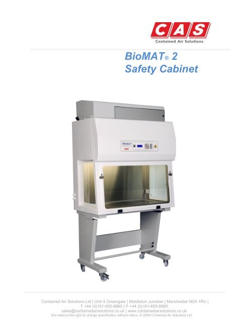
<strong>BioMAT®</strong> 2<br />
<strong>Safety</strong> <strong>Cabinet</strong><br />
Contained Air Solutions Ltd | Unit 4 Greengate | Middleton Junction | Manchester M24 1RU |<br />
T +44 (0)161-655-8860 | F +44 (0)161-655-8865<br />
sales@containedairsolutions.co.uk | www.containedairsolutions.co.uk<br />
We reserve the right to change specification without notice. © 2009 Contained Air Solutions Ltd
Contents<br />
Section Description<br />
Section 1<br />
Your Manual<br />
Section 2<br />
Using your <strong>Cabinet</strong><br />
Section 3<br />
<strong>Cabinet</strong> Control Panel<br />
Section 4<br />
Filter Replacement<br />
Section 5<br />
Service & Spares<br />
1.1<br />
1.2<br />
1.3<br />
1.4<br />
1.5<br />
1.6<br />
1.7<br />
2.1<br />
2.2<br />
2.3<br />
2.4<br />
2.5<br />
2.6<br />
2.7<br />
2.8<br />
3.1<br />
3.2<br />
3.3<br />
3.4<br />
3.5<br />
4.1<br />
4.2<br />
4.3<br />
4.4<br />
5.1<br />
5.2<br />
5.3<br />
5.4<br />
General Description<br />
Quality Assurance/CE compatibility<br />
<strong>Cabinet</strong> Siting<br />
Installation<br />
Avoiding Disturbances<br />
Technical Data<br />
Your Manual<br />
Switches & Indicators<br />
Start Up Procedure<br />
Shut Down Procedure<br />
Cleaning Procedure<br />
Fumigation & Formalin Quantities<br />
Fumigation Procedure<br />
Airflow Measurements<br />
Ultraviolet Radiation<br />
Display<br />
Alarm Circuits<br />
Electrical Protection<br />
Fan Speed Control<br />
Engineers Menu<br />
Downflow HEPA Filter<br />
Re-circ HEPA Filter<br />
Exhaust HEPA Filter<br />
General Notes<br />
Service Schedule<br />
Spares List<br />
Drawings (attached)<br />
Wiring Diagrams (attached)
General Description – 1.1<br />
Your BioMAT 2 Microbiological <strong>Safety</strong> <strong>Cabinet</strong> has been designed to provide optimum<br />
performance for both operator and product protection. Using the latest in microprocessor and<br />
fan technology, it is designed to exceed the performance requirements of the European<br />
Microbiological <strong>Safety</strong> <strong>Cabinet</strong> Standard EN12469:2000. The safety cabinet carcass and all<br />
seals are maintained under negative pressure ensuring air cannot leak out during normal<br />
operation.<br />
Class 2 <strong>Safety</strong> <strong>Cabinet</strong>s offer both operator and product protection; they ensure any aerosols<br />
generated within the cabinet are filtered via high efficiency filtration (HEPA) prior to being<br />
dispersed back into the laboratory or to atmosphere. Operator protection is provided by an air<br />
curtain across the working aperture of the front screen. Protection of the products from<br />
external contamination is provided by a unidirectional downflow of sterile air into the working<br />
area.<br />
The Class 2 Microbiological <strong>Safety</strong> <strong>Cabinet</strong> can be supplied as standard in either of the<br />
following two modes:<br />
Re-circulating Type – Exhaust air from the safety cabinet is passed through two<br />
high efficiency filters (HEPA) before being released back into the laboratory. The<br />
exhaust air is made up of approximately 40% of the total air volume handled by<br />
the safety cabinet. Approximately 60% of the air is re-circulated within the safety<br />
cabinet and passes through a high efficiency (HEPA) filter to ensure sterility<br />
within the work area.<br />
Exhaust Type – Exhaust air from the safety cabinet is passed through a high<br />
efficiency filter (HEPA) before being extracted to atmosphere through a fan<br />
assisted extract system. The exhaust air is made up of approximately 40% of the<br />
total air volume handled by the safety cabinet. Approximately 60% of the air is<br />
re-circulated within the safety cabinet and passes through a high efficiency<br />
(HEPA) filter to ensure sterility within the work area.
Quality Assurance – 1.2<br />
Although fully tested before leaving our factory as part of the ISO 9001:2008 Quality Assurance<br />
Programme, the specified performance will only be maintained if your cabinet is sited correctly<br />
and regularly serviced. CAS can only accept responsibility for correct functioning of your<br />
cabinet if: -<br />
<strong>Safety</strong> <strong>Cabinet</strong> is correctly sited in the laboratory to avoid any adverse<br />
conditions within the room that may affect the level of operator protection.<br />
It has been installed and commissioned by CAS trained personnel or approved CAS<br />
agents.<br />
Extension, modification, relocation, repairs or other maintenance is carried out by<br />
CAS personnel or persons authorised by CAS or, in the case of electrical work, by<br />
qualified electricians.<br />
In the case of repair or maintenance, replacement parts supplied by CAS must be<br />
used.<br />
The electrical installation surrounding the unit and to which it is connected<br />
comply with the latest IEC regulations.<br />
The unit is used and maintained in compliance with the instructions contained in<br />
this manual.<br />
CE Declaration of Conformity<br />
CAS declares that the equipment supplied conforms to the following CE directives—<br />
Machinery 2006/42/EC<br />
Electro Magnetic Compatibility 2004/108/EC<br />
Low Voltage 2006/95/EC
<strong>Cabinet</strong> Siting – 1.3<br />
The siting of your <strong>Safety</strong> <strong>Cabinet</strong> is extremely important. Air currents and the movement of<br />
people in the laboratory can adversely affect the performance.<br />
<strong>Safety</strong> <strong>Cabinet</strong>s should be sited away from;<br />
Doors and windows which open<br />
Draughts caused by ventilation and air conditioning units<br />
Pedestrian traffic routes<br />
Other safety cabinets or fume cupboards<br />
Adjacent fridge & Incubator doors<br />
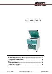
These points are of particular relevance to class 2 safety cabinets. The diagram shown below<br />
indicates some suggested locations for the correct siting of safety cabinets and highlights some<br />
situations which should be avoided.<br />
3 4<br />
2<br />
SUPPLY GRILLE<br />
HORIZONTAL<br />
LAMINAR FLOW<br />
Position 1 - An acceptable site not affected by disruptive air currents<br />
Position 2 - Well sited<br />
Position 3 -Poorly sited if windows open – If not it should be a safe distance<br />
from the cabinet opposite.<br />
Position 4 -Poorly sited – can be affected by air currents from the opening door,<br />
through traffic and the horizontal laminar flow workstation<br />
sited directly opposite.<br />
1
Installation – 1.4<br />
<strong>Safety</strong> <strong>Cabinet</strong>s are sophisticated items of equipment containing delicate filters which require<br />
expertise in their safe handling and installation into laboratories.<br />
For exhaust type safety cabinets the exhaust ductwork route should ideally be surveyed and<br />
ductwork installation be carried out by qualified engineers as it forms an integral part of the<br />
system relating to the overall performance of the cabinet and is required to conform to various<br />
safety standards.<br />
A poorly installed cabinet may compromise the protection provided by the cabinet to both<br />
personnel and work being handled and may present a hazard to other occupants of the<br />
building and the public.<br />
• Make-up Air<br />
It is important that any make-up air compensating for the air exhausted from the safety<br />
cabinet does not cause draughts to the discomfort of the laboratory staff or detriment of the<br />
cabinet performance.<br />
Air supply diffusers should be positioned more than 1500mm away from the front of the safety<br />
cabinet and have a maximum velocity of no more than 0.30m/sec.<br />
• Commissioning<br />
When any safety cabinet is installed, it is necessary to carry out a number of commissioning<br />
checks in order to ensure it is fully operational and that the performance on site satisfies the<br />
current standard BS EN 12469:2000. This includes measuring the airflows, testing the HEPA<br />
filters with a suitable challenge aerosol and a KI Discus Test (operator protection test) to assess<br />
the containment of the cabinet.<br />
CAS employs a team of fully trained installation and commission engineers to carry out all work<br />
necessary. This ensures that all new safety cabinets operate to the desired performance.<br />
• Site Surveys<br />
If you have any queries regarding the siting of your safety cabinets we will be only too pleased<br />
to arrange a site survey by one of our regionally based technical support staff.<br />
• Periodic Maintenance & Servicing<br />
To maintain safety cabinets at their optimum level of performance and to ensure lifetime<br />
operation, regular servicing is necessary. CAS provides a full servicing and maintenance scheme<br />
tailored to suit your individual needs. For more information on this please contact our service<br />
department on 0161-655-8860.
Avoiding Disturbances – 1.5<br />
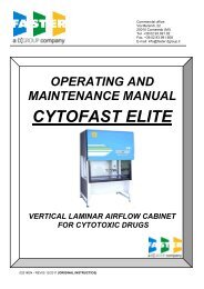
The sketches below show recommendations for avoiding disturbances for both cabinet<br />
operator and safety cabinet performance.<br />
1000<br />
Keep pedestrians away from the front<br />
of your safety cabinet<br />
1500<br />
Bench<br />
300<br />
Keep clear of adjacent wall<br />
C<br />
1500<br />
Position well away from the door openings<br />
Position clear of bench opposite Keep clear of structural columns Keep well away from opposite wall<br />
300<br />
2000
Technical Data – 1.6<br />
<strong>Cabinet</strong> Size 900mm 1200mm 1500mm 1800mm<br />
Dimensions<br />
External Dimensions (w/d/h) 900/640/1400 1200/640/1400 1500/640/1520 1800/640/1520<br />
Internal Dimensions (w/d/h) 760/550/700 1060/550/700 1360/550/700 1660/550/700<br />
Work Tray (w/d) 720/400 1020/400 1320/400 1620/400<br />
Opening to Work Area (w/h) 710/200 1010/200 1310/200 1610/200<br />
Weight Typical Kg 180 230 280 330<br />
Loading Capacity<br />
Work Surface Kg 50 50 50 50<br />
Air Volumes Typical<br />
Exhaust Air Volume m³/sec 0.09 0.130 0.160 0.190<br />
Re-circ Air Volume m³/sec 0.130 0.190 0.240 0.290<br />
Pressure Drop Typical<br />
Exhaust Clean Filters Pa 400 400 400 400<br />
Exhaust Dirty Filters Pa 550 550 550 550<br />
HEPA Filter Data<br />
HEPA Type H14 (EN1822) H14 (EN1822) H14 (EN1822) H14 (EN1822)<br />
Efficiency @ 0.3µ 99.999% 99.999% 99.999% 99.999%<br />
Heat Gains Typical<br />
Exhaust Watts 190 190 270 350<br />
Re-circ Watts 100 100 135 175<br />
Noise Typical<br />
Noise Level dB (A)
Your Manual – 1.7<br />
This user manual has been prepared to provide a basic operating and maintenance instruction.<br />
It is intended to supplement existing in-house procedures and codes of practice, and not to<br />
replace them. If further advice is required on the use or maintenance of this equipment, the<br />
staff of Contained Air Solutions Ltd. will be pleased to assist wherever possible.
Switches & Indicators – 2.1<br />
The diagram below shows a typical control panel membrane layout for the BioMAT 2<br />
safety cabinet.<br />
BioMAT 2 BioMAT<br />
CLASS 2 MICROBIOLOGICAL SAFETY CABINET<br />
COMPLIES WITH BS EN 12469:2000<br />
0<br />
1<br />
AIRFLOW SAFE<br />
2<br />
DESCRIPTION LEGEND COLOUR FUNCTION<br />
A – <strong>Cabinet</strong> Operation Green<br />
Starts / Stops power supply to<br />
fans and control circuits.<br />
B – Lights Yellow Controlling power to lights.<br />
C – Gas Valve (Optional) Black<br />
D – Alarm Mute<br />
Red<br />
E – Fumigate Orange<br />
F – UV Lights (Optional)<br />
G – Key Switch<br />
0<br />
Blue<br />
1 Grey Border<br />
To activate solenoid Gas Valve.<br />
Will only function when cabinet is<br />
in safe working condition.<br />
To mute audible alarm. Fault<br />
indication on display will remain<br />
until fault is rectified.<br />
To activate fumigation cycle. Will<br />
only operate when cabinet is<br />
switched OFF.<br />
To activate power to UV Lights.<br />
Will only operate when cabinet<br />
and lights are switched OFF.<br />
Key switch for supervisor control,<br />
used to prevent cabinet operation<br />
during fumigation.
Start Up Procedure – 2.2<br />
The following notes are for guidance where local laboratory instructions do not exist or are<br />
inappropriate. They should complement, not replace, existing codes of practice issued by your<br />
Laboratory <strong>Safety</strong> Officers.<br />
Ensure power supply to the cabinet is switched on, as evidenced by the main display<br />
being illuminated. The key switch on the front of the cabinet must be turned to position ‘ 1’ =<br />
(ON).<br />
Press the green switch ‘ A’ on the control panel – this will energise the exhaust fan<br />
followed by the downflow fans. The main display will show `AIRFLOW STABILISING` for 60<br />
seconds, once airflows are settled the display will show `AIRFLOW SAFE`. On start up the<br />
audible alarm will sound until airflows are safe; this may be muted using the Alarm Mute<br />
switch `D’ .<br />
NOTE: Should the airflows change significantly and fall out of the specifications laid<br />
down in EN12469:2000 cabinet alarms will be automatically activated.<br />
Switch on the interior lighting using switch ‘ B’ . Lighting can be activated when the<br />
cabinet is OFF; this can be used if loading or un-loading the cabinet with equipment prior to<br />
use.
Shut Down Procedure – 2.3<br />
The work area should be cleared of any apparatus / equipment and cleaned in<br />
accordance with laboratory codes of practice. The cabinet should be left running for a few<br />
minutes to clear any residual aerosols.<br />
Switch off the interior light using switch `B`<br />
Switch off the cabinet using switch `A`.<br />
Place the closure panel / Night door over the working aperture once complete.
Cleaning Procedure – 2.4<br />
Regular cleaning is very important to prevent the build-up of dirt and hence potentially<br />
infectious material. Routine swabbing of work surfaces with 70% v/v IMS (ethanol) or IPA<br />
(Isopropyl Alcohol) is recommended.<br />
For cleaning the work surfaces, swabbing with a mild detergent in warm water is very<br />
effective. Phenolic or Cresolic disinfectants should be avoided as they may stain the white<br />
surfaces with a brownish colour. If they are used, any spillage should be quickly rinsed with<br />
clean water and mopped up with an absorbent tissue. Most of the quaternary ammonium<br />
compounds and the Glutaraldehyde based surface disinfectants are suitable.<br />
To facilitate cleaning of the work zone and the interior, the whole front screen / visor may be<br />
opened and lowered from the top, supported by the hinges at the lower edge. It is good<br />
practice to clean the inside of the viewing screen to ensure adequate visibility of the working<br />
zone. Always consult the Laboratory <strong>Safety</strong> Officer before carrying out this procedure.<br />
Warning<br />
If Hypochlorites are used to clean the stainless<br />
steel interior of the safety cabinet they will<br />
initially cause rust spots and over time may lead<br />
to further damage.
Fumigation & Formalin Quantities – 2.5<br />
When handling hazardous materials the air space inside the cabinet should be decontaminated<br />
regularly and always before servicing and following any spillages. Fumigation by formaldehyde<br />
gas is the recommended decontamination procedure for biological hazards although there are<br />
alternative methods available including VHP decontamination and Ozone decontamination.<br />
To facilitate the fumigation a sequence has been incorporated in the cabinet controls, this is<br />
detailed under fumigation procedure.<br />
A convenient way of generating sufficient formaldehyde is to boil off Formalin (40%<br />
formaldehyde BP or equivalent) in a suitable vessel such as a formalin vaporiser. These are<br />
available from CAS.<br />
Formalin Quantities<br />
Always consult your Laboratory <strong>Safety</strong> Officer<br />
prior to fumigation of a safety cabinet.<br />
** If in doubt ask **<br />
The recommended quantity stated in BS EN12469:2000 on Page 40 Annex J, Part 2 is 60ml<br />
formaldehyde solution mixed with 60ml distilled water per cubic meter of cabinet volume.<br />
However this quantity is now considered in excess of that required to achieve a satisfactory kill.<br />
We have therefore produced the following table based on quantities employed by users of<br />
large numbers of <strong>Safety</strong> <strong>Cabinet</strong>s.<br />
If you still consider that the quantities recommended in the British Standard are to be used,<br />
you may find on completion of the sterilisation cycle that high quantities of fluids containing<br />
formaldehyde are present in the cabinet.<br />
<strong>Cabinet</strong> Size 900mm 1200mm 1500mm 1800mm<br />
Formalin 15ml @40% 20ml @ 40% 25ml @ 40% 30ml @ 40%<br />
Distilled Water 15ml 20ml 25ml 25ml
Fumigation Procedure – 2.6<br />
Switch off the cabinet fans by pressing the green button ‘ A’ on the control panel.<br />
For re-circulating type safety cabinets the fumigation extract kit (optional) should be<br />
fitted to the cabinet discharge and ensure that the manual damper is fully closed. For cabinets<br />
connected to a duct system proceed as follows:<br />
Fill the formalin vaporiser with the correct amount of Formalin (see section 2.5 for<br />
quantities) and screw on the aluminium cap – finger tight, having checked the gasket in the cap<br />
is undamaged. If the vaporiser is free standing, place on the cabinet work tray, plug into<br />
cabinet internal socket and switch on. Now fit the closure panel / night door, if using a<br />
lightweight closure panel additional sealing tape will be required around the outside face to<br />
ensure no leakage during fumigation. It is advisable to use a non permeable type tape that will<br />
not leave a residue once removed.<br />
Now press the fumigation button `E’ and the display will show `FUMIGATION IN<br />
PROGRESS’ . A countdown timer will be shown directly below in minutes e.g. `285 MINS`.<br />
During the first hour of the fumigation cycle the internal fans (downflow fans) will cycle for 5<br />
seconds at 20 minute intervals, this ensures formaldehyde is well dispersed within the cabinet.<br />
Warning<br />
Ensure all laboratory personnel are aware that<br />
the fumigation is taking place; appropriate<br />
warning notices should be put on all doors<br />
entering the laboratory and on the cabinet being<br />
fumigated.<br />
The cabinet should be left for a minimum of 6 hours, preferably overnight.<br />
Note: Once the ‘ fumigate’ button has been activated DO NOT SWITCH CABINET ON<br />
until the cycle has been completed.<br />
On completion the cabinet will display `FUMIGATION COMPLETE` and `READY TO<br />
VENT`. When ready, press the fumigation button to exit the cycle and then press the<br />
green button `A` to purge the cabinet of formaldehyde gas.
For re-circulating type safety cabinets press the ‘ fumigate’ button to complete cycle and<br />
open the manual shut-off damper on the fumigation adaptor kit (Optional) having first<br />
fitted the extract tubing and placed the discharge point in a location approved by the<br />
Laboratory <strong>Safety</strong> Officer.<br />
** When fumigating a re-circulating type safety cabinet where venting is unobtainable,<br />
a mobile carbon filter unit may be required. **<br />
Switch on the cabinet and then remove the sealing tape. To avoid formaldehyde being<br />
drawn out of the cabinet remove the rubber bung when using a 100% sealing closure<br />
panel.<br />
Within the first few minutes of purging, the majority of the formaldehyde gas within<br />
the safety cabinet will be removed. However due to the fact that formaldehyde<br />
adheres to the surfaces of the cabinet and within the media of HEPA filters, we<br />
recommend that the cabinet be run continuously for at least 6 hours before the<br />
cabinet is serviced or work re-commences.<br />
Remove the (optional) fumigation kit from the cabinet discharge before<br />
commencing to use the cabinet.<br />
** Any poly-formaldehyde residue in the vaporiser may be removed by heating with water<br />
containing a little mild detergent at neutral pH.<br />
General Note<br />
Other methods of generating formaldehyde and other methods of cabinet decontamination<br />
can be employed; prior to using alternative methods your Laboratory <strong>Safety</strong> Officer should be<br />
consulted. Contained Air Solutions will be pleased to advise if they are able, but a detailed<br />
knowledge of every technique cannot be guaranteed.<br />
If your cabinet is fitted with ports to allow fumigation using Vaporised Hydrogen<br />
Peroxide (VHP) please refer to the VHP equipment manufacturer’ s manual for the<br />
correct application of this technique.
Airflow Measurements – 2.7<br />
It is recommended that the downward airflow be checked regularly, i.e. weekly or monthly<br />
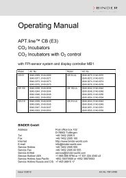
according to cabinet usage. A rotating vane type anemometer with a head diameter of about<br />
100mm is considered satisfactory. On 1200mm wide cabinets, take 8 readings, namely four<br />
along a line one quarter of the depth of the working space forward of the rear wall, and four<br />
along a line the same distance behind the front window on a horizontal plane 100mm above<br />
the top edge of the working aperture. Anemometer positions for the 1200mm & 1800mm<br />
sizes of cabinet are illustrated below. The results should be recorded to monitor cabinet<br />
performance over time.<br />
1/4<br />
1/2<br />
1/4<br />
1/12<br />
1/4<br />
1/2<br />
1/4<br />
1/8 1/4 1/4 1/4 1/8<br />
1/6<br />
1200mm wide<br />
1/6<br />
1/6<br />
1800mm wide<br />
1/6 1/6<br />
1/12
Unidirectional Downflow Air<br />
NOTE: - The unidirectional downflow air within the cabinet is set up during<br />
commissioning to give an average velocity of 0.3 to 0.35m/sec measured at<br />
a horizontal plane 100mm above the top edge of the working aperture. The<br />
limitations laid down in the standard are minimum 0.25m/sec - maximum<br />
0.50m/sec with no one reading being greater than +/- 20% of the mean<br />
velocity.<br />
This preset velocity can only vary if (a) the soiling of the downflow filter occurred, or (b) should<br />
there be a fan failure.<br />
NOTE: - We recommend that the downflow velocity be checked on a regular basis and the<br />
results recorded to monitor cabinet performance over time.
Ultraviolet Radiation (Optional) – 2.8<br />
Ultraviolet Radiation (UV) lamps may be fitted as an optional extra; these can be fitted as new in<br />
our factory or retrofitted at a later date on site. If installed the cabinet will have 2 short wavelength<br />
Ultraviolet (UV) tubes emitting 254 nano metres fitted to the inside work area of the safety cabinet.<br />
As a safety feature the UV tubes are interlinked with the cabinet lights to prevent them being used<br />
when the cabinet is in use.<br />
Over time, the effective life of UV tubes is known to reduce; therefore we would recommend UV<br />
tubes are replaced on an annual basis to ensure maximum efficiency.<br />
Applications<br />
Many bacteria are quite resistant to UV Radiation, and may require prolonged exposure for<br />
sterilisation. Dry and/or protein covered organisms may be protected against UV and may be only<br />
slightly affected if at all. However, moist, vegetative cells without too much protein covering are<br />
killed with reasonable effectiveness after 3-4 hours exposure.<br />
Warning<br />
Extreme care must be exercised when using UV<br />
radiation. Consult your Laboratory <strong>Safety</strong> Officer<br />
prior to use.<br />
UV Radiation can cause burns to unprotected skin<br />
and it is very important not to look directly at the<br />
illuminated tubes with the naked eye.
Display - 3.1<br />
The cabinet display is located in the centre of the control membrane; it incorporates<br />
backlighting to ensure all signs can be clearly seen from the operating position.<br />
Typical display during normal operation shown below:<br />
AIRFLOW SAFE<br />
BioMAT 2<br />
In the event of an alarm condition the display will clearly indicate the fault; this will remain<br />
displayed until the fault is rectified.<br />
Typical display during alarm condition shown below:<br />
DOWNFLOW FAIL<br />
Should the cabinet produce an alarm condition it may be necessary to arrange for a Service<br />
Engineer to attend site, in such cases please contact our Service Department on 0161-655-<br />
6183.
Alarm Circuits – 3.2<br />
There are three standard alarm circuits on the BioMAT 2 Re-circulating and Exhaust type <strong>Safety</strong><br />
<strong>Cabinet</strong>s.<br />
1. INFLOW<br />
Sensed by an accurate pressure sensor mounted on the main printed circuit board and<br />
connected via tubing to the sensing points within the cabinet body, this will sense low airflow<br />
caused by fan failure or filter soiling, and transmit the signal to the display meter on the front<br />
panel and alarm circuit. In the event the alarm is triggered the display will show `LOW<br />
AIRFLOW`, and the audible alarm will sound, this can be muted using the alarm mute button.<br />
1. DOWNFLOW<br />
Sensed by an accurate pressure sensor mounted on the main printed circuit board and<br />
connected via tubing to the sensing points within the cabinet body, this will sense low airflow<br />
caused by fan failure or filter soiling, and transmit the signal to the display meter on the<br />
front panel and alarm circuit. In the event the alarm is triggered the display will show<br />
`DOWNFLOW FAIL` and the audible alarm will sound, this can be muted using the alarm mute<br />
button.<br />
2. FRONT SCREEN<br />
Front screen position is monitored by a micro-switch fitted to the front screen<br />
assembly. When opened the display will show `VISOR OPEN’ and an audible alarm will sound.<br />
This can be muted using the alarm mute button.<br />
** The alarm circuit is activated each time the cabinet is switched on.<br />
It is important to ensure that the pressure tubing is not damaged or split where it is connected<br />
to the pressure sensor. The pressure sensor, in the event of inadequate airflow in either part<br />
of the system, will cause the alarm circuit to be activated with a flashing red indicator on the<br />
alarm mute button, an intermittent audible alarm tone, and the alarm system will clearly show<br />
on the display. The audible alarm tone can be silenced by depressing the ‘ alarm mute’ button<br />
on the control panel after which the red light will remain continuously lit until the correct<br />
airflow is reinstated or the cabinet is switched off.
Electrical Protection – 3.3<br />
Warning<br />
Fuses<br />
Ensure the <strong>Safety</strong> <strong>Cabinet</strong> is isolated from the<br />
mains supply prior to opening access panels.<br />
There are 11 fuses mounted on the printed circuit board to protect the electrical circuits of the<br />
cabinet. The cabinet controls are housed behind the front control panel which is secured with<br />
two screws located across the bottom edge. Once removed the control panel will hinge<br />
upwards to facilitate access to the main printed circuit board.<br />
For full details on fuse ratings and the circuits they protect please see the wiring diagram<br />
attached to this manual.
Fan Speed Control – 3.4<br />
Both the inflow and downflow fans can be adjusted via the engineer’ s menu please see section<br />
3.5 for more information.<br />
To maintain optimum performance during routine planned maintenance it may be necessary<br />
to increase cabinet fan speeds to overcome filter soiling. This can be adjusted via the front<br />
control panel membrane using the Engineer’ s Menu.<br />
Warning<br />
It is important any changes to fan speeds must be<br />
made by a CAS service engineer or alternative<br />
competent service provider, failure to do this may<br />
result in the warranty being invalid.
Engineer’ s Menu – 3.5<br />
Warning<br />
The buttons located on the front control membrane have a second function once access to the<br />
Engineer’ s Menu has been gained.<br />
** In order to gain access to the Engineer’ s Menu the cabinet must be switched OFF **<br />
STANDARD SWITCH PANEL ARRANGEMENT<br />
It is important any changes within the Engineer’ s<br />
Menu be conducted by a CAS service engineer or<br />
alternative competent service provider; failure to<br />
do so may result in the warranty being invalid.<br />
SOFT BUTTON ARRANGEMENT<br />
TO ENTER `ENGINEERS MENU` BUTTON 1 SHOULD HELD DOWN FOR >5 SECONDS<br />
TO EXIT `ENGINEERS MENU` BUTTON 1 SHOULD HELD DOWN FOR >5 SECONDS<br />
USE BUTTON 2 TO START / STOP THE FANS
Engineer’ s Menu Sequence<br />
L OW A LARM<br />
40 Pa<br />
HIGH ALARM<br />
80 Pa<br />
DOWNFLOW ALARM<br />
120 P a<br />
INFL OW F AN<br />
65 %<br />
DOW NFLO W FAN<br />
40 %<br />
U.V. LIG HTING<br />
060 MINUTE S<br />
TIME ADJUS T<br />
14:54<br />
E XHAUST SENSOR<br />
20 Pa<br />
S ERV ICE TIMER<br />
RE S ET<br />
INITIALISE VALUE<br />
INITIALIS E ( 0)<br />
N O<br />
N O<br />
N O<br />
N O<br />
N O<br />
N O<br />
N O<br />
N O<br />
N O<br />
YES<br />
YES<br />
YES<br />
YES<br />
YES<br />
YES<br />
YES<br />
YES<br />
YES<br />
YES
Downflow HEPA Filter – 4.1<br />
The downflow filter is a single HEPA filter mounted immediately above the working area.<br />
Access is gained by opening the control panel door.<br />
Warning<br />
IMPORTANT<br />
<strong>Cabinet</strong> must be decontaminated prior to changing any HEPA filters, see section 2.6<br />
Only replace or examine filters if authorised to do so by the <strong>Safety</strong> Officer or the person in<br />
charge of the laboratory. To remove any filters wear disposable gloves, an apron, overalls<br />
and appropriate face covering, especially eye protection.<br />
Ensure the <strong>Safety</strong> <strong>Cabinet</strong> is isolated from the<br />
mains supply prior to opening access panels.<br />
The front control panel is hinged at the top and retained by fixing screws in the lower edge,<br />
when opened it can be supported by two stays. Behind the front control panel is the main<br />
access panel held in place by several screws. Care should be taken to ensure the panel is<br />
supported prior to releasing the last screw.<br />
Behind the access panel is the downflow fan module and the downflow HEPA filter. Turning<br />
the jacking screw clockwise at each side a little at a time until free from the filter will raise the<br />
fan module. The downflow filter may then be drawn forward and out of the cabinet body, this<br />
can then be disposed of as recommended by site regulations.<br />
To replace, first ensure that all surfaces have been cleaned and are free from matter.<br />
Carefully remove the new filter from its protective packing.<br />
Inspect both exposed surfaces for signs of damage. Any damage should be reported to the<br />
supplier immediately.<br />
The filter should be slid carefully into the cabinet taking care not to damage the gaskets, if<br />
necessary by supporting the filter from within the work area. The fan module is then carefully<br />
lowered by turning the jacking screws anti-clockwise a little at a time so as to compress the<br />
filter gasket to approximately half its original thickness. The panels may then be replaced, and<br />
the filter and its gasket tested for leaks by challenging with DOP or equivalent aerosol and<br />
scanning the surface with the probe of a forward light scattering photometer.
Re-circ HEPA Filter – 4.2<br />
The double HEPA filter is located on the top of the main body of the cabinet held in place by<br />
two compression fasteners.<br />
Warning<br />
To remove filter, release fasteners, lift module until filter can be removed. Slide filter forward<br />
and out and dispose of as recommended by site regulations<br />
To replace, first ensure that all surfaces have been cleaned and are free from matter.<br />
Remove new filter from its protective packing.<br />
IMPORTANT<br />
<strong>Cabinet</strong> must be decontaminated prior to changing any HEPA filters, see section 2.6<br />
Only replace or examine filters if authorised to do so by the <strong>Safety</strong> Officer or the person in<br />
charge of the laboratory. To remove any filters wear disposable gloves, an apron, overalls<br />
and appropriate face covering, especially eye protection.<br />
Ensure the <strong>Safety</strong> <strong>Cabinet</strong> is isolated from the<br />
mains supply prior to opening access panels.<br />
Inspect both exposed surfaces for signs of damage. Any damage should be reported to the<br />
supplier immediately.<br />
Slide filter carefully into position. Lock fasteners, ensuring filter is correctly positioned and<br />
gaskets are compressed to about half their original thickness.<br />
The filter and its gaskets should be tested for leaks by challenging with DOP or equivalent<br />
aerosol and scanning the surface with the probe of a forward light scattering photometer.
Exhaust HEPA Filter – 4.3<br />
The single HEPA filter is located on the top of the main body of the cabinet held in place by<br />
either two compression fasteners or jacking screws.<br />
Warning<br />
To remove filter, release fasteners or jacking screws, lift module until filter can be removed.<br />
Slide filter forward and out and dispose of as recommended by site regulations<br />
To replace, first ensure that all surfaces have been cleaned and are free from matter.<br />
Remove new filter from its protective packing.<br />
IMPORTANT<br />
<strong>Cabinet</strong> must be decontaminated prior to changing any HEPA filters, see section 2.6<br />
Only replace or examine filters if authorised to do so by the <strong>Safety</strong> Officer or the person in<br />
charge of the laboratory. To remove any filters wear disposable gloves, an apron, overalls<br />
and appropriate face covering, especially eye protection.<br />
Ensure the <strong>Safety</strong> <strong>Cabinet</strong> is isolated from the<br />
mains supply prior to opening access panels.<br />
Inspect both exposed surfaces for signs of damage. Any damage should be reported to the<br />
supplier immediately.<br />
Slide filter carefully into position. Lock fasteners or jacking screws, ensuring filter is correctly<br />
positioned and gaskets are compressed to about half their original thickness.<br />
The filter and its gaskets should be tested for leaks by challenging with DOP or equivalent<br />
aerosol and scanning the surface with the probe of a forward light scattering photometer.
General Notes – 4.4<br />
Do not store equipment inside the Microbiological <strong>Safety</strong> <strong>Cabinet</strong>. The amount of<br />
equipment should be kept to a minimum to reduce the disruption to the airflow patterns<br />
within the cabinet.<br />
A Bunsen burner should not be used inside the cabinet.<br />
Great care should be taken to prevent litter such as disposable gloves or tissues from<br />
being sucked through the airways at the rear of the work area. These can lodge and reduce<br />
the airflow through the cabinet. It is good practice to clean underneath the work tray<br />
regularly. Always consult the Laboratory <strong>Safety</strong> Officer before carrying out this procedure.<br />
The failsafe solenoid operated gas valve (If fitted) will only allow gas to flow when the<br />
cabinet is switched on and there is a satisfactory airflow. Any interruption in the power supply<br />
or failure of air supply necessitates manual resetting of the valve by depressing the switch on<br />
the control panel marked ‘ gas valve’ .<br />
As a safety feature the UV (If fitted) tubes are interlinked with the cabinet lights to<br />
prevent them being used when the cabinet is in use.<br />
We recommend cabinet users to consult their own laboratory safety information. Other<br />
publications available include:<br />
Science Reviews Ltd, Occupational Hygiene Monograph No.9<br />
British Standard BS EN 12469:2000 & 5726-2000 Part 5<br />
Australian Standard AS2567<br />
American National Sanitation Foundation Standard No. 49<br />
We would also recommend the latest guidelines issued by the UK Advisory Committee on<br />
Dangerous Pathogens (ACDP). These documents contain much useful information on the<br />
performance, installation, testing, use and limitations of Microbiological <strong>Safety</strong> <strong>Cabinet</strong>s.
Service Schedule 5.1<br />
SERVICE SCHEDULE 5.1<br />
Class II Microbiological <strong>Safety</strong> <strong>Cabinet</strong>s<br />
Schedule of work included in service agreement<br />
1 Filter Integrity Test (D.O.P) on all main filter(s) and seals<br />
2 Airflow Profiling ensuring compliance to latest British & European Standards<br />
3 Operator Protection Testing (K.I. Discus) 1 x Per Annum<br />
4 Check and adjust alarm parameters & control functions as required<br />
5 Check and adjust electrical and electronic controls as related to the airflow system<br />
6 Check and adjust operation of exhaust system as required<br />
7 Mechanically inspect cabinet components and duct connections (if fitted)<br />
8 Change main filters as necessary (Supply and fitting subject to additional charge)<br />
9 Prepare computer generated Service Report<br />
Above work to be carried out twice each service year<br />
(Operator Protection Test (K.I. Discus) carried out once per year unless instructed otherwise<br />
Service schedules can be tailored to suit individual needs<br />
For a competitive Quotation please contact our service<br />
Department on<br />
0161-655-8860
Spares List 5.2<br />
Shown below are ordering codes for the most common parts used on the BioMAT 2 <strong>Safety</strong><br />
<strong>Cabinet</strong>s. In addition to these items we stock a vast range of Spares, consumables and optional<br />
extras. If you cannot see what you require please give us a call on the telephone number<br />
shown below.<br />
** Please note cabinet serial number must be quoted when ordering **<br />
UK: Overseas:<br />
Tel: 0161-655-8860 Tel: +44-161-655-8860<br />
Fax: 0161-655-8865 Fax: +44-161-655-8865<br />
Item<br />
ORDERING CODES<br />
BioMAT 2<br />
1200mm<br />
BioMAT 2<br />
1500mm<br />
BioMAT 2<br />
1800mm<br />
Downflow HEPA Filter FIL 001 FIL 025 FIL 005<br />
Exhaust HEPA Filter FIL 002 FIL 167 FIL 048<br />
Recirc HEPA Filter FIL 003 FIL 117 FIL 007<br />
Downflow Fan FAN 050 FAN 050 FAN 050<br />
Exhaust Fan FAN 050 FAN 057 FAN 057<br />
Main PCB ELC 325 ELC 325 ELC 325<br />
Control Membrane LAB 114 LAB 114 LAB 114<br />
Light Tube ELC 077 ELC 097 ELC 049<br />
UV Light Tube ELC 061 ELC 061 ELC 061<br />
Key Switch ELC 326 ELC326 ELC 326<br />
Standard Closure Panel CCM 725 CCM 800 CCM 772<br />
100% Sealing Closure Panel CCM 726 CCM 801 CCM 773<br />
Formalin Vaporiser CCP 083 CCP 083 CCP 083<br />
Fumigation Adaptor Box (Recirc) CCM 111 CCM 802 CCM 112