00112EN Rev.04 - FlowFAST V P - Wolf Laboratories
00112EN Rev.04 - FlowFAST V P - Wolf Laboratories
00112EN Rev.04 - FlowFAST V P - Wolf Laboratories

Create successful ePaper yourself
Turn your PDF publications into a flip-book with our unique Google optimized e-Paper software.
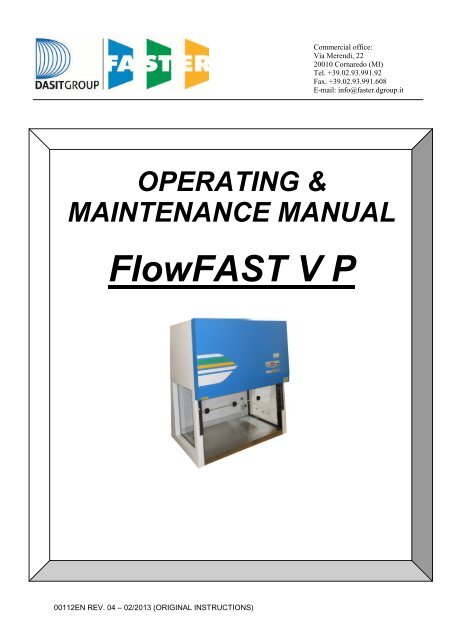
<strong>00112EN</strong> REV. 04 – 02/2013 (ORIGINAL INSTRUCTIONS)<br />
Commercial office:<br />
Via Merendi, 22<br />
20010 Cornaredo (MI)<br />
Tel. +39.02.93.991.92<br />
Fax. +39.02.93.991.608<br />
E-mail: info@faster.dgroup.it<br />
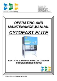
OPERATING &<br />
MAINTENANCE MANUAL<br />
<strong>FlowFAST</strong> V P
CONTENTS<br />
1. GENERAL .......................................................................................................................... 2<br />
2. INSTALLATION .................................................................................................................. 3<br />
2A. INSTRUCTIONS AND CHECKS ON DELIVERY ............................................................................. 3<br />
2B. INSTALLATION REQUIREMENTS ................................................................................................... 3<br />
2C. ELECTRIC/GAS CONNECTIONS and INSTALLATION OF THE WORK SURFACE...................... 4<br />
3. OPERATION PRINCIPLES ................................................................................................ 6<br />
4. OPERATION ...................................................................................................................... 7<br />
4A. SCOPE .............................................................................................................................................. 7<br />
4B. CONTROLS OF SYSTEM AND PERFORMANCES ........................................................................ 7<br />
4C. REMOTE SIGNALS (Optional for automatic regulation) ................................................................... 7<br />
4D. SYMBOLS of CONTROL BOARD .................................................................................................... 8<br />
4E. OPERATOR MENU......................................................................................................................... 12<br />
5. HOUR COUNTER / UV TIMER (Optional) ........................................................................ 17<br />
5A. Hours counter .................................................................................................................................. 17<br />
5B. UV Timer ......................................................................................................................................... 17<br />
5C. Energy save..................................................................................................................................... 18<br />
6. DISPOSAL OF WASTES ................................................................................................. 19<br />
7. LIMITATIONS ................................................................................................................... 20<br />
8. OPERATING PROCEDURES .......................................................................................... 21<br />
8A. PRELIMINARY CHECKS ................................................................................................................ 21<br />
8B. SWITCHING ON the FLOWFAST V CABINET .............................................................................. 21<br />
8C. SWITCHING OFF FLOWFAST V CABINET .................................................................................. 21<br />
8D. U.V. LAMP POSITION .................................................................................................................... 22<br />
9. MAINTENANCE ............................................................................................................... 23<br />
9A. INSTRUCTION FOR DAILY CLEANING OF VERTICAL LAMINAR FLOW CABINETS (by<br />
users) 23<br />
9B. REPLACEMENT OF HEPA FILTER (by technical assistance personnel) ...................................... 24<br />
9C. REPLACEMENT OF MOTOR-FAN (by technical assistance personnel) ....................................... 25<br />
9D. REPLACEMENT OF FLUORESCENT LAMPS (by user) ............................................................... 26<br />
9E. LIST OF SPARE PARTS................................................................................................................. 27<br />
10. TROUBLESHOOTING – Probable causes of malfunctions .......................................... 28<br />
11. TRANSPORT, PACKING an STORAGE INSTRUCTIONS ........................................... 29<br />
12. ADDITIONAL INFORMATION ...................................................................................... 31<br />
12A. GUARANTEE .................................................................................................................................. 31<br />
12B. ADDRESS OF TECHNICAL ASSISTANCE (for the distributor) ..................................................... 31<br />
13. DIAGRAM FOR MAINTENANCE OPERATIONS .......................................................... 32<br />
13A. LEGENDA ....................................................................................................................................... 32<br />
13B. <strong>FlowFAST</strong> V P ................................................................................................................................. 33<br />
14. FRONTAL DIAGRAM ................................................................................................... 34<br />
14A. <strong>FlowFAST</strong> V P ................................................................................................................................. 34<br />
15. SIDE DIAGRAM ............................................................................................................ 35<br />
15A. <strong>FlowFAST</strong> V P ................................................................................................................................. 35<br />
16. SENSOR LIST .............................................................................................................. 36<br />
17. WIRING DIAGRAM ...................................................................................................... 37<br />
18. DECLARATION OF CONFORMITY ............................................................................. 41<br />
<strong>00112EN</strong> REV. 04 – 03/2013 1
1. GENERAL<br />
<strong>FlowFAST</strong> V P VERTICAL LAMINAR AIRFLOW CABINETS provide high protection of material to be<br />
manipulated against contamination by protecting the working area from micro-organisms and airborne<br />
contaminants.<br />
These cabinets have been specifically designed to meet the demands of modern industrial laboratories<br />
where the protection of the product is required.<br />
Especially suitable for applications such as:<br />
• Manipulation of material in a sterile area<br />
• Cell culture<br />
• Microbiology<br />
• Molecular biology - PCR<br />
The performances of the cabinets are detailed in the TESTING CERTIFICATE herewith, in compliance<br />
with the requirements of:<br />
• ISO 14644-1 Cleanrooms and associated controller environments – Part 1: classification of air<br />
cleanliness<br />
on electric safety:<br />
• EN 61010-1 Safety requirements for eletrical equipment for measurement, control and laboratory<br />
use Part 1: general requirements.<br />
All Faster’s cabinets are provided with high insertion loss filters.<br />
<strong>FlowFAST</strong> V P vertical laminar airflow cabinets are marked "CE" (see label stuck on the right-hand side of<br />
the cabinet near the feeding cable) and meet the European Directive:<br />
2006/42/EC Directive of the European Parliament and of the Council on machinery<br />
2004/108/EC Directive of the European Parliament and of the Council on the approximation of the<br />
laws of the Member States relating to electromagnetic compatibility<br />
2006/95/EC Directive of the European Parliament and of the Council on the harmonisation of the<br />
laws of Member States relating to electrical equipment designed for use within certain<br />
voltage limits<br />
The <strong>FlowFAST</strong> cabinets comply with the above-mentioned Directives ONLY if the instrumentation that is<br />
connected to the electric socket (optional) positioned inside the work chamber are marked "CE", or in any<br />
case meet the standards mentioned above aiming to avoid any electromagnetic interference.<br />
Faster s.r.l. cannot be held responsible for malfunctions, damage to people or property due to<br />
non-compliance, poor or no maintenance, or improper use of the cabinet.<br />
N.B. : FLOWFAST V P cabinets MUST ABSOLUTELY NOT BE USED for handling pathogenic<br />
materials<br />
<strong>00112EN</strong> REV. 04 – 03/2013 2
2. INSTALLATION<br />
2A. INSTRUCTIONS AND CHECKS ON DELIVERY<br />
Considering the importance of the use of the laminar airflow <strong>FlowFAST</strong> V P cabinets and the need to<br />
keep them in optimum conditions, installation plays a major role to reach this aim.<br />
<strong>FlowFAST</strong> V P cabinets are positioned on a bench, wrapped in an extensible film and contained in a<br />
package of multi-layer strapped cardboard.<br />
For a general check of the instrument, having placed it in its utilization site, opened the package and<br />
removed the extensible film, control that the instrument has not suffered bucklings or scratches due to<br />
transport or wrong handling of the package.<br />
In case of a possible further transport, packing and storage by user after a first utilization period (e.g.:<br />
change of laboratory or factory), get in touch with the technical assistance service or the distributor for<br />
more accurate and precise indications or for a possible intervention by specialized technicians.<br />
The <strong>FlowFAST</strong> V cabinets, with or without package, shall be always sheltered from rain.<br />
2B. INSTALLATION REQUIREMENTS<br />
Install the cabinet sheltered from draughts and heat sources (radiators, ventil-convectors), to ensure a<br />
good working.<br />
• Install the instrument in a room with a low degree of dust and well aerated.<br />
• Place the instrument far from doors and windows, which may cause malfunctions.<br />
• Place the instrument in places where there is no people movement.<br />
• The door of the room should be in such a position relatively to the cabinet as to prevent draught<br />
effects.<br />
• A distance of 10 cm at least between the room ceiling and the outlet of exhausted air is of the<br />
essential.<br />
• The temperature shall never fall under 0°C, to prevent the humidity present in the filtering screen<br />
from freezing, which might damage filters’ meshes:<br />
o max. temperature: 40°C<br />
o max. humidity: 80% at 31°C, linear drop in relative humidity down to 50% relative humidity<br />
at 40°C.<br />
Before connecting the cabinet to the mains, control the voltage and power necessary on the plate near the<br />
feed cable. The room shall be compulsory provided with earthing connection to gas and/or vacuum<br />
networks, if so required by the cabinet.<br />
As to the connection with gas and/or vacuum networks, read carefully chapter 2C.<br />
The quantity of heat generated by the cabinet is the following for the three models respectively:<br />
<strong>FlowFAST</strong> V 12 450 kcal/h<br />
<strong>FlowFAST</strong> V 15 500 kcal/h<br />
<strong>FlowFAST</strong> V 18 520 kcal/h<br />
To this heat, the heat due to possible bunsen burners or other instruments utilized by the client in the<br />
working area under laminar airflow should be added.<br />
The installation is made by technicians authorized by Faster s.r.l.<br />
<strong>00112EN</strong> REV. 04 – 03/2013 3
2C. ELECTRIC/GAS CONNECTIONS and INSTALLATION OF THE WORK SURFACE<br />
The electric connection of the cabinet model <strong>FlowFAST</strong> is made by connecting the power cable located on<br />
the upper part of the right side of the cabinet to a suitable power point (see technical table). When the<br />
cabinet is connected, the green light on the control panel switches on.<br />
If so provided for by the laws in force, insert upstream on the feed line an automatic protection overload<br />
switch provided with a differential relay, whose rated switching voltage should not exceed 30 mA.<br />
The right side of the hood is also provided with one gas/vacuum intake with manual tap.<br />
The connection with the gas/vacuum intake is made according to the type of connection: town gas or<br />
industrial gas (air, vacuum, nitrogen, etc.).<br />
The cabinet must be connected with the town gas mains through an approved pipe, for safety reasons.<br />
For the installation of the work surface, proceed as follows:<br />
• remove the protective paper from the work surface resting against the back of the cabinet, taking care<br />
not to scratch its surface,<br />
• open the safety front window,<br />
• clean the work surface with a damp cloth soaked in alcohol or soapy water or with a commonly<br />
available product designed for stainless steel,<br />
• place the work surface in the work chamber, allowing the back to slide on the supporting basis of<br />
chamber up to its bottom wall<br />
• close the shatterproof front window<br />
<strong>00112EN</strong> REV. 04 – 03/2013 4
Techincal Features Table<br />
Description Unit <strong>FlowFAST</strong> V 12 <strong>FlowFAST</strong> V 15 <strong>FlowFAST</strong> V 18<br />
Overall Dimensions (W x D x H) mm 1350 x760x1545 1655 x760x1545 1960 x760x1545<br />
Usefull dimensions (W x D x H) mm 1198x609x755 1503x609x755 1808x609x755<br />
Maximum front aperture mm 480 480 480<br />
Working aperture mm 250 250 250<br />
Weigh Kg 197 237 267<br />
Noise level dB (A) 750<br />
Nitrogen, CO2, compressed air - maximum pressure bar 4 4 4<br />
Fuel gas- maximum pressure mbar 20 20 20<br />
Main voltage V 230V AC 2P+T 230V AC 2P+T 230V AC 2P+T<br />
Frequency Hz 50 50 50<br />
Maximum power consumption W 1220 1350 1455<br />
Current A 6,1 7,4 8,1<br />
Electrical class 1 1 1<br />
Protection level IP20 IP20 IP20<br />
Internal outlet (maximum current for all the sockets: 4A) 2P+T 230V 4A 2P+T 230V 4A 2P+T 230V 4A<br />
Fluorescent lamps W 1x36 1x58 1x58<br />
<strong>00112EN</strong> REV. 04 – 03/2013 5
3. OPERATION PRINCIPLES<br />
The following are the working principles of the vertical laminar airflow cabinet model <strong>FlowFAST</strong> V P:<br />
• The air is sucked from a prefilter placed on the top of the cabinet<br />
• the pressurized air pushed into the plenum of the motor-fan goes through the absolute filter and<br />
then downwards, in laminar flow, into the working chamber. Most of the air from here is exhausted<br />
trough the frontal opening.<br />
• A little part of the air is sucked trough the slot in the rear part of the work chamber and<br />
recirculated<br />
<strong>00112EN</strong> REV. 04 – 03/2013 6
4. OPERATION<br />
4A. SCOPE<br />
The <strong>FlowFAST</strong> V P vertical laminar airflow cabinet class ISO 5 is manufactured according to the<br />
requirements of the international standards for the protection of the material manipulated in the working<br />
chamber.<br />
Our <strong>FlowFAST</strong> V P cabinets fully meet the requirements of Class ISO 5 according to ISO EN 14644-1<br />
4B. CONTROLS OF SYSTEM AND PERFORMANCES<br />
<strong>FlowFAST</strong> V P cabinet is provided with a manual electronic regulation system, or, if installed, with<br />
automatic regulation system, to keep the airflow speed constant in the work chamber even by a<br />
progressive clogging of the HEPA filter up highest pressures.<br />
The front panel of hardened glass is hinged to facilitate the introduction of bulky objects and is provided<br />
with gas-springs for opening/closing and holding the open position.<br />
4C. REMOTE SIGNALS (Optional for automatic regulation)<br />
The electronic control board can be improved with an output signal: it is possible to obtain a 12 Vdc output<br />
to connect a led light or alternatively a Normally Open voltage free contact to be connected to an external<br />
circuit. This signal can be set in three different modes:<br />
Motor ON:<br />
The signal starts when ventilation is turned ON and stops when ventilation is OFF.<br />
Alarm:<br />
That signal is ON in case of any flow alarm and it is OFF when air flow rate is in the correct range.<br />
LAF OK:<br />
That signal is ON when air flow rate is in the correct range and it is OFF in case of any flow alarm.<br />
<strong>00112EN</strong> REV. 04 – 03/2013 7
4D. SYMBOLS of CONTROL BOARD<br />
List and description of all the symbols and controls of the control panel:<br />
12 13 14<br />
0 1 2 3 4 10 11 5 6 7 8 9<br />
0 MAIN SWITCH:<br />
Position "0" in the "0" position, the green light of the mains voltage is on [12]; the LCD<br />
displays the model name.In this position the operator can activate only the<br />
fluorescent light [7], the U.V. lamp [2] and the power outlet [8] (with plug<br />
installed) and can activate the data stored in the microprocessor by<br />
pressing the “Right Arrows” key [6].<br />
Position "I" Press key "I" [0], insert the password using the small numbers in the right<br />
lower corner of the keys and press SET. Default password is 5 – 4.<br />
When the password is typed in the green led of the switch lights up and<br />
the cabinet starts operating, the motor-blower is powered and first<br />
"CHECK PANEL" then "STAND-BY" appears on the display till the air flow<br />
reaches the pre-set value. In addition, an audible alarm will sound<br />
intermittently during this stand-by period, alerting the operator not to start<br />
working yet. When the audible alarm stops and the message "STAND-<br />
BY" disappears from the display, the cabinet is ready for use. The air<br />
velocity is displayed.<br />
NOTE: In any case, it is advisable to wait 5 minutes before starting work.<br />
<strong>00112EN</strong> REV. 04 – 03/2013 8
1 STAND BY (speed reduction) By pushing the corresponding red key the password (the same to<br />
start the ventilation) is requested. Once confirmed the password the<br />
function is enabled. When it is enabled, the corresponding red LED lights<br />
up and, for single fan cabinets, the air speed is about 30% lower than<br />
their nominal speeds. The light and the gas electrovalve cannot be<br />
switched on. If they are on, they switch off automatically. If the PCB for<br />
the automatic regulation is installed following two messages appear<br />
alternatively:<br />
and:<br />
>>>ATTENTION>DO NOT WORK
5-6 LEFT/RIGHT ARROWS Use the arrow keys to scroll the menu: if pressed the following data will<br />
appear on the display:<br />
U.V. Lamp Residual Lifetime: Shows the operating time of the U.V.lamp<br />
pre-set by the user with the appropriate keys. The LCD will display (for<br />
example) "U.V. TIME=XXXX h" . When such time is over, the message<br />
"U.V. LIFETIME OVER" will appear on the line below.<br />
1, 2, 3 Residual lifetime of filters : it is the operation time of the filters<br />
installed in the cabinet that can be programmed by the user.<br />
The LCD will display (for example)" RES. TIME FILTER 1=XXXX:XX<br />
h:min". When such time is over, the message "CHECK FILTER (i.e.) 1".<br />
will appear on the line below.<br />
The filters installed in the cabinet follow the numbering listed below<br />
TYPE of FILTER NUMBER<br />
MAIN HEPA 1<br />
EXHAUST HEPA 2<br />
ACTIVE CARBON 3<br />
LAF Power: it is shown indirectly by the power supply voltage of the<br />
motor, expressed as percentage of max. load voltage displayed also in<br />
proportion by a bar.<br />
The display shows the notice(es.): "MOT.LAF = XX % " (max.100%).<br />
Operating Time: Shows the operating time of the cabinet from the<br />
moment when the main switch is positioned on "I"<br />
The LCD will display (for example) "WORK TIME=XXXXXh”. This value<br />
cannot be reset.<br />
7 LIGHT This switches on the fluorescent light; when enabled, the display shows<br />
"Light on". Switching on the fluorescent light automatically the U.V. lamp<br />
switches off.<br />
8 SOCKET This supplies voltage; when enabled, if the PCB for the automatic<br />
regulation is installed the display shows "POWER ON". The global current<br />
for all the sockets installed on the cabinet is 4 Amps.<br />
9 GAS (optional) This activates the control for opening/closing the gas electrovalve; when<br />
enabled, if the PCB for the automatic regulation is installed the display<br />
shows "GAS ON". It operates only when the ventilation is running to<br />
prevent possible over-heating and risks of damaging the HEPA filter.<br />
10 ESC ESC key deletes the operation of data input and goes back to the starting<br />
condition.<br />
When an alarm condition occurs, which is shown also by the message<br />
appearing on the LCD. By pushing "ESC" (if enabled) the alarm stops<br />
sounding. If the cause of the alarm is not resolved after 2 minutes the<br />
buzzer starts to sound again.<br />
<strong>00112EN</strong> REV. 04 – 03/2013 10
11 SET SET key lets you enter the different functions or confirm the data input<br />
going back to the upper level.<br />
12 LINE The green mains light switches on if the unit is connected to the mains<br />
and the line is live<br />
13 DISPLAY Rearlight liquid crystal "LCD" display composed of 2 lines of 20 characters<br />
each showing the operating parameters and alarms.<br />
14 ALARM When an alarm occurs the red LED lights up.<br />
<strong>00112EN</strong> REV. 04 – 03/2013 11
4E. OPERATOR MENU<br />
It’s possible enter the operator menu, with the cabinet in stand-by mode and when the cabinet is switched on, by pressing at the same time the keys “ESC” (7) and “ARROW UP” (6).<br />
If enter the operator menu while the cabinet is running, it’s possible to set only the “ALARM CLOCK” and the “TIMER”.<br />
STAND-BY MODE<br />
PASSWORD<br />
ESC + UP arrow<br />
OPERATOR MENU<br />
Timer set up<br />
OPERATOR MENU<br />
Alarm clock set up<br />
OPERATOR MENU<br />
UV program<br />
OPERATOR MENU<br />
UV residual time<br />
OPERATOR MENU<br />
Filter residual time<br />
OPERATOR MENU<br />
Language<br />
OPERATOR MENU<br />
Set up the clock<br />
OPERATOR MENU<br />
Change Password<br />
OPERATOR MENU<br />
Alarms display<br />
TIMER SET UP<br />
hh:mm<br />
ALARM CLOCK SET UP<br />
Enable YES/NO<br />
UV PROGRAM<br />
Duration: hh:mm<br />
UV LAMP<br />
SET UP XXXX<br />
SET FILTER 1<br />
Set XXXX<br />
LANGUAGE<br />
Italiano<br />
SET UP THE CLOCK<br />
Date and hour<br />
CURRENT PASSWORD:<br />
Psw:<br />
ALARM CLOCK SET UP<br />
Date and hour<br />
UV PROGRAM<br />
ON: Date and hour<br />
SET FILTER 2<br />
Set XXXX<br />
LANGUAGE<br />
English<br />
SET UP PASSWORD:<br />
Psw:<br />
SET FILTER 3<br />
Set XXXX<br />
LANGUAGE<br />
Francais<br />
VERIFIY PASSWORD:<br />
Psw:<br />
<strong>00112EN</strong> REV. 04 – 03/2013 12<br />
LANGUAGE<br />
Deutsch<br />
LANGUAGE<br />
Espanol
U.V. LAMP RESIDUAL LIFETIME:<br />
• use "UP/DOWN arrow" keys [5/6] to choice the desired menu<br />
• select “U.V. LAMP RESIDUAL LIFETIME.” and press "SET" [10] key; the display will show:<br />
U.V. LAMP RESIDUAL LIFETIME<br />
set XXXX<br />
• where XXXX shows the number of the hours set for lifetime of the U.V. lamp.<br />
• Use the “up and down arrow” keys to adjust the hours parameter<br />
• Then press the "SET" key [8] to confirm the data and/or go back to previous menu<br />
• To conclude programming, press ESC” [7] key.<br />
FILTERS RESIDUAL LIFETIME:<br />
• use "UP/DOWN arrow" keys [5/6] to choice the desired menu<br />
• select “FILTERS RESIDUAL LIFETIME.” and press "SET" [8] key; the display will show:<br />
FILTER 1 RESIDUAL LIFETIME<br />
set XXXX<br />
where XXXX shows the number of the hours set for lifetime of the FILTER 1<br />
• Use the “up and down arrow” keys to adjust the hours parameter<br />
• Then press the "SET" key [8] to confirm the data and pass to filter 2 and so on up to filter 5 (as for<br />
relation between number and type of filter see table par. 4C)<br />
• To conclude programming, press ESC” [7] key.<br />
LANGUAGE SELECTION<br />
• use "UP/DOWN arrow" keys [5/6] to choice the desired menu<br />
• select “LANGUAGE” and press the “SET” key and the following message will be shown on the<br />
display:<br />
LANGUAGE<br />
English<br />
• With the “up and down arrow” keys select the desired language (Italian, English, French, German,<br />
Spanish).<br />
• Press the “SET” key to confirm and exit the “LANGUAGE” menu.<br />
• press “ESC” [7] key to go out.<br />
<strong>00112EN</strong> REV. 04 – 03/2013 13
SET UP THE CLOCK<br />
• use "UP/DOWN arrow" keys [5/6] to choice the desired menu<br />
• select “SET UP THE CLOCK.” and press "SET" [8] key; the display will show:<br />
SET UP THE CLOCK<br />
set XXXX<br />
• Use the “left and right arrow” keys to select the desired parameter and set it using the “up and down<br />
arrow” keys<br />
• Then press the "SET" key to confirm the data and/or go back to previous menu<br />
• To conclude programming, press ESC” [7] key.<br />
PASSWORD CHANGE<br />
• use "UP/DOWN arrow" keys [5/6] to choice the desired menu<br />
• select “PASSWORD CHANGE” and press "SET" [8] key; the display will show:<br />
CURRENT<br />
PSW:<br />
• digit the present Password then press “SET” key<br />
• digit the new Password then press “SET” key<br />
SET UP PASSWORD<br />
PSW:<br />
VERIFY PASSWORD<br />
PSW:<br />
• digit the password again and then press “SET” key to confirm the data and/or go back to previous<br />
menu<br />
• To conclude programming, press ESC” [7] key.<br />
DISPLAY OF HISTORICAL FILES<br />
• use "UP/DOWN arrow" keys [5/6] to choice the desired menu<br />
• select “ALARMS” and press "SET" [8] key;<br />
• use "UP/DOWN arrow" keys to scroll through the list of the possible troubles happened . The list is in<br />
chronological order and contains up to 64 voices<br />
• To conclude programming, press ESC” [7] key.<br />
<strong>00112EN</strong> REV. 04 – 03/2013 14
ALARM CLOCK<br />
• use "UP/DOWN arrow" keys [5/6] to choice the desired menu<br />
• select “ALARM CLOCK” and press "SET" [8] key; the display will show:<br />
Alarm clock set up<br />
Set up XXXX<br />
• Use the “left and right arrow” keys to select the desired parameter and set it using the “up and down<br />
arrow” keys<br />
• Then press the "SET" key to confirm the data and/or go back to previous menu<br />
• Press “ESC” to abort the procedure<br />
• When the set time is reached the buzzer start to ring and the display show this message<br />
ALARM CLOCK<br />
ALARM<br />
• Press the “ESC” key to silence the acoustic signal<br />
IMPOSTAZIONE TIMER<br />
• use "UP/DOWN arrow" keys [5/6] to choice the desired menu<br />
• select “PASSWORD CHANGE” and press "SET" [8] key; the display will show:<br />
Timer set up<br />
Set up XXXX<br />
• Use the “left and right arrow” keys to select the desired parameter and set it using the “up and down<br />
arrow” keys<br />
• Then press the "SET" key to confirm the data and/or go back to previous menu<br />
• Press “ESC” to abort the procedure<br />
• At the end of the countdown the buzzer start to ring and the display will show this message:<br />
TIMER<br />
ALARM<br />
• Press the “ESC” key to silence the acoustic signal<br />
<strong>00112EN</strong> REV. 04 – 03/2013 15
UV TIMER<br />
• use "UP/DOWN arrow" keys [5/6] to choice the desired menu<br />
• select “PASSWORD CHANGE” and press "SET" [8] key; the display will show:<br />
UV TIMER<br />
Duration XXXX<br />
• Use the “left and right arrow” keys to select the desired parameter and set it using the “up and down<br />
arrow” keys<br />
• Then press the "SET" key to confirm the data<br />
• The display shows:<br />
UV TIMER<br />
DATE XXXX<br />
• Use the “left and right arrow” keys to select the desired parameter and set it using the “up and down<br />
arrow” keys<br />
• Then press the "SET" key to confirm the data and/or go back to previous menu<br />
<strong>00112EN</strong> REV. 04 – 03/2013 16
5. HOUR COUNTER / UV TIMER (Optional)<br />
Available only in English language.<br />
5A. Hours counter<br />
During the standard operating of the cabinet the display shows:<br />
The hour counter starts when the ventilation is switched ON and stop when the ventilation is turned OFF<br />
It is possible RESET the hour counter pressing in sequence the following keys:<br />
ESC – Arrow down – Arrow up – SET<br />
After this the display will show this message:<br />
WORKTIME RESET<br />
Confirm? No<br />
Change the answer with the arrow keys and press SET<br />
5B. UV Timer<br />
When the UV key is pressed on the display the following message will appear.<br />
Now with the arrow keys, it is possible set the time for the UV lamp; when SET is pressed the countdown<br />
starts and when it reaches “0:00” the UV lamp switches off (if the operator sets the time “0:00” the UV lamp<br />
still turned ON until the UV key is pressed again).<br />
If necessary press the UV key to switch off the UV lamp before the countdown reaches “0:00”<br />
<strong>00112EN</strong> REV. 04 – 03/2013 17
5C. Energy save<br />
The hours counter/UV timer PCB has the function: Energy save:<br />
When the cabinet is in Stand by mode, after few minutes the display switch OFF (only the green led still<br />
remain lighted).<br />
To switch on the display it is necessary press any key<br />
The functions of this PCB are available only in English language.<br />
<strong>00112EN</strong> REV. 04 – 03/2013 18
6. DISPOSAL OF WASTES<br />
DISPOSAL OF ELECTRIC AND ELETTRONIC DEVICES (AEE)<br />
INFORMATION FOR EUROPEAN UNION USER<br />
This symbol on the device means that when it needs to be disposed, it must be<br />
handled separately from urban waste.<br />
At the moment of the disposal, contact the dealer, to receive information about the<br />
collect and disposal in accordance with the laws in force in the country.<br />
Appropriate disposal of this product will help to prevent potential negative effects on health and environment<br />
and to promotes re-use and / or recycling of materials of the equipment.<br />
The improper disposal of the product by holder involves the application of sanctions in accordance with the<br />
regulations in their own country.<br />
INFORMATION FOR USERS OUTSIDE THE EUROPEAN UNION<br />
This symbol is valid only in the European Union If you want to dispose this product, contact your local<br />
authorities or dealer and ask for the correct method of disposal.<br />
<strong>00112EN</strong> REV. 04 – 03/2013 19
7. LIMITATIONS<br />
PRECAUTIONS for the correct use of the cabinet<br />
Listed below are the most important guidelines to be followed and the main substances to be avoided to<br />
ensure the correct use of the <strong>FlowFAST</strong> V cabinet:<br />
• NEVER USE chlorine-based substances (e.g. sodium hypochlorite) as they are corrosive for the metal<br />
structure of the cabinet and in particular for stainless steel parts.<br />
• NEVER MANIPULATE pathogens of any group or biosafety level.<br />
• DO NOT use ethyl alcohol as a sterilizing substance if a heat source is used under the cabinet,<br />
• DO NOT use cosmetic powders, nail-polish, hair-spray and cosmetics in general during work,<br />
• DO NOT eat, drink or smoke in the working zone,<br />
• AVOID substances that release explosive vapours.<br />
In addition, when working under the cabinet, AVOID:<br />
• the introduction of extraneous material<br />
• the introduction of paper/clothes that might clog the holes of the work surface<br />
• working in the part of the work surface near the front opening of the cabinet (longitudinally slotted zone)<br />
• upstream contamination of the material, putting the hands or an object between the absolute filter and<br />
the sterile material<br />
• working under the cabinet if the airflow has not yet been activated, and a suitable work condition has<br />
been achieved. After the cabinet switching on and if the work requires sterile conditions, chemical<br />
sterilization of the work chamber must be carried out using a cloth soaked in bactericide. Then wait for<br />
20÷30 minutes for the bactericide to take effect.<br />
• using in the work zone large size bunsen burners, as the flame might damage the absolute filter located<br />
in the upper part of the working area<br />
ATTENTION: The U.V. radiations emitted by the germicidal U.V. lamp can cause erythemas<br />
and conjunctivitis.<br />
AVOID EXPOSURE OF SKIN AND EYES TO DIRECT RADIATION<br />
<strong>00112EN</strong> REV. 04 – 03/2013 20
8. OPERATING PROCEDURES<br />
8A. PRELIMINARY CHECKS<br />
Before carrying out any type of work, the following conditions should be verified:<br />
- that the cabinet power cable is connected to a 230V-50Hz outlet (if not distinct voltages/frequencies are<br />
shown on the label stuck near the power cable)<br />
- that the work area inside the cabinet is free from materials used during the previous session<br />
- that the work chamber has been cleaned/sterilized.<br />
8B. SWITCHING ON the FLOWFAST V CABINET<br />
To switch on the cabinet, proceed as indicated below:<br />
- Switch on the cabinet by pressing the key ON/OFF (if the PCB for the automatic regulation is<br />
installed insert the password: press the button 5 , button 4 and then the button SET )<br />
- Switch on the lighting, by pushing the key<br />
The cabinet is ready to work. Wait 5 minutes before starting any operation (see chapter 5).<br />
During this period of time, introduce ALL and ONLY the material indispensable for working in the<br />
internal working zone of the cabinet.<br />
8C. SWITCHING OFF FLOWFAST V CABINET<br />
At the end of the work session, proceed as follows:<br />
- Remove the material from the internal work chamber<br />
- Clean the work surface and the inside walls of the chamber, as indicated in the “Cleaning instructions”<br />
(chapter 7A)<br />
- Turn off the light by pushing the key<br />
- Turn off the cabinet by pressing the "ON/OFF” key (if the PCB for the automatic regulation is<br />
installed insert the password: press the button 5 , button 4 and then the button SET )) or<br />
press the "SPEED REDUCTION" key<br />
In case UV lamp is installed in the cabinet, switch on the germicidal lamp by pushing the “U.V.” yellow button<br />
.<br />
The U.V. lamp will switch on only if the front aperture is closed with the relevant panel.<br />
<strong>00112EN</strong> REV. 04 – 03/2013 21
8D. U.V. LAMP POSITION<br />
U.V. rays could damage the HEPA filter, when using the U.V. lamp be careful to don’t place it too close to the main<br />
HEPA filter. In the picture is shown the correct position for the U.V: lamp.<br />
<strong>00112EN</strong> REV. 04 – 03/2013 22
9. MAINTENANCE<br />
9A. INSTRUCTION FOR DAILY CLEANING OF VERTICAL LAMINAR FLOW CABINETS (by<br />
users)<br />
or:<br />
• Clean the outside of the <strong>FlowFAST</strong> V cabinet, made of stainless steel AISI 304, using a damp cloth<br />
soaked in alcohol or soapy water or some other commonly available products for stainless steel.<br />
• Clean the outside of the <strong>FlowFAST</strong> V cabinet, made of varnished iron-carbon sheet steel, using a<br />
damp cloth soaked in soapy water or some other commonly available products for varnished metal<br />
surfaces.<br />
• Clean-sterilize the internal work chamber with a bactericidal agent chosen according to the type of<br />
micro-organism manipulated (e.g., ethanol, phenolic compositions, aldehydes, quaternary<br />
ammonium salts, etc.).<br />
For efficient cleaning, spray the bactericidal agent on the side walls, the back wall and the perforated work<br />
surface.<br />
If material has been spilled during the work session, clean the work surface, then remove it using the small<br />
grips fixed on same, clean the spilled materials contained in the collection tank located under the table and<br />
remove all spilled material by means of absorbent paper.<br />
For thorough cleaning we suggest the use of a 70% ethanol solution or a solution of other bacteriostatic<br />
agents.<br />
N.B.: Never use solutions containing free chlorine (for instance, sodium hypochlorite), which cause<br />
corrosion to steel and stainless steel, resulting in irreparable damage to the cabinet structure.<br />
IMPORTANT: before carrying out the following operations of replacement, disconnect the<br />
cabinet<br />
<strong>00112EN</strong> REV. 04 – 03/2013 23
9B. REPLACEMENT OF HEPA FILTER (by technical assistance personnel)<br />
For the safety of the personnel and the environment, the use of PVC gloves is recommended as well<br />
as the collection of the replaced HEPA filters in polyethylene bags.<br />
Replacement of main/exhaust HEPA filter (see guide-drawing for maintenance operations)<br />
1. Switch off the cabinet and disconnect it from the mains<br />
2. Open the control panel [1] unscrewing the bolts [2] with the proper key and lock it with the relevant stirrups.<br />
1<br />
2<br />
3. Remove the internal panel [3] unscrewing the relevant fastening screws.<br />
4. Rotate the threaded bars [4]and remove the central frame to release the HEPA filter [6].<br />
Central frame<br />
4<br />
Stirrup<br />
5. Remove the HEPA filter wearing PPD and put it in a hermetically sealed polythene bag.<br />
6. Place the additional gasket (if it is not already present) on the filter shoulder frame opposite the shoulder gasket<br />
of filter (already present).<br />
7. Install the new HEPA filter.<br />
8. Lock the HEPA filter [6] by means of the threaded locking bars [4]<br />
Important: Having replaced the filters, proceed with the calibration of motor-fan speed, and perform<br />
also a control with a "light scattering" meter.<br />
<strong>00112EN</strong> REV. 04 – 03/2013 24
Replacement of prefilter<br />
1. Switch off the cabinet and disconnect it from the mains<br />
2. Unscrew the screw of the frame to unlock the prefilter<br />
3. Replace the prefilter<br />
4. Fasten the frame with the screw<br />
9C. REPLACEMENT OF MOTOR-FAN (by technical assistance personnel)<br />
1. Proceed as indicated in sub-section "Replacement of HEPA filters", from 1 to 3 points.<br />
2. Remove the frame [19] in front of the fan and release the textile plenum<br />
15<br />
11<br />
3. Disconnect electrical connectors from terminal board in the plastic box.<br />
4. Unscrew fastening screws [10] of the main motor-fan [11] and the flow sensor group [17] (optional)<br />
unscrewing the relevant stirrup from the motor-fan<br />
<strong>00112EN</strong> REV. 04 – 03/2013 25<br />
10<br />
17
5. Remove the main motor-fan [11] including the side stirrup [12].<br />
12<br />
6. Position the new motor-fan after having mounted again the flow sensor group (Optional) [15] and the<br />
relevant stirrup.<br />
7. Fasten the motor-fan with the relevant screws and reconnect electrical connectors.<br />
8. Proceed as indicated in the sub section "Replacement of HEPA filters", from 13 to 15 points.<br />
9D. REPLACEMENT OF FLUORESCENT LAMPS (by user)<br />
1. Open the front control panel [1] unscrewing the fastening locks [2],<br />
2. Replace the lamps [16]<br />
3. Close the front control panel [1] with the fastening locks [2].<br />
<strong>00112EN</strong> REV. 04 – 03/2013 26<br />
11
9E. LIST OF SPARE PARTS<br />
CODE DESCRIPTION 12 15 18<br />
V50 000000200 DDM 9/9 300W 1<br />
V50 000000420 DDM 10/10 550W 1 1<br />
V50 000100360 HEPA absolute filter, 610x1220x69 with laminator sheet 1<br />
V50 000100370 HEPA absolute filter, 610x1525x69 with laminator sheet 1<br />
V50 000100380 HEPA absolute filter, 610x1830x69 with laminator sheet 1<br />
V50 000202010 Prefilter, 457x610x12 1<br />
V50 000202020 Prefilter, 457x762x12 1<br />
V50 000202030 Prefilter, 457x915x12 1<br />
K60 011230900 Front upper glass 1<br />
K60 011530900 Front upper glass 1<br />
K60 011830900 Front upper glass 1<br />
K60 011231000 Front lower glass 1<br />
K60 011531000 Front lower glass 1<br />
K60 011831000 Front lower glass 1<br />
K60 011430800 Left side safety glass 1 1 1<br />
K60 011431400 Right side safety glass 1 1 1<br />
V30 000008000 Power card PWLAF 1 1 1<br />
V30 000008100 CPU card CPULAF (optional) 1 1 1<br />
V30 000005200 Keyboard 1 1 1<br />
V20 000006900 Line filter FN2070A-10-06 1 1 1<br />
V20 000006040 36W Fluorescent lamp 1<br />
V20 000006050 58W Fluorescent lamp 1 1<br />
<strong>00112EN</strong> REV. 04 – 03/2013 27
10. TROUBLESHOOTING – Probable causes of malfunctions<br />
PROBLEM CAUSE REMEDY<br />
Cabinet does not work – the electricity supply has been<br />
cut off at the mains<br />
– Electronic board out of order<br />
– Blown fuse(s)<br />
– check the voltage input to the<br />
cabinet<br />
– Replace PCB<br />
– Replace fuses<br />
Alarm: “HEPA filters check” Main HEPA filter clogged Replace HEPA filter<br />
“minimum LAF alarm”.<br />
[Possible contamination of the<br />
product but protection of the<br />
environment]<br />
“Black-out ” Alarm<br />
(probable exchange of air<br />
between the work chamber and<br />
the outside and possible<br />
contamination of the<br />
environment)<br />
HEPA filters clogged . Replace HEPA filters.<br />
The main motor-fan does not work<br />
Blackout<br />
Check the terminal voltage of the<br />
power card of the main motor-fan<br />
Check F7 fuse on the power card<br />
Replace the power card<br />
Replace the microprocessor card<br />
Check the feeding cable, the<br />
connection plug/socket, the power<br />
supply line<br />
Press “ESC” [7] key to silence the<br />
alarm<br />
Alarm “Sensors failure” Failure of sensor XX Replace XX sensor.<br />
Alarm: “No encoder input LAF” No signal from LAF flow sensor Replace the LAF sensor<br />
<strong>00112EN</strong> REV. 04 – 03/2013 28
11. TRANSPORT, PACKING an STORAGE INSTRUCTIONS<br />
IMPORTANT: Disconnect power and sterilize the unit before performing any of the following<br />
operations<br />
The following instructions are essential if the end user needs to transport, pack and store a cabinet after a<br />
period of routine use (e.g. laboratory/plant moving):<br />
• Disconnect tubes for gas/vacuum<br />
• Remove the work surface and and cover it with a protective film.<br />
• Open the two lock handles of the front safety glass<br />
• If the cabinet is to be moved from a laboratory to another in the same building:<br />
- on a table with wheels: it is sufficient to put the cabinet on the table; do not place it on one side on<br />
the back panel.<br />
- by a forklift : put the cabinet on a pallet to ensure good stability and to protect the basin under the<br />
cabinet against damage in transport.<br />
• Take care not to damage protruding parts (e.g.: gas/vacuum taps, exhaust duct) when passing through<br />
doors/windows<br />
• If the cabinet must be kept temporarily unused at the final destination, cover the cabinet itself with a<br />
protective film (pluriball or expansible films) taking care to protect also the exhaust duct, especially from<br />
dusty<br />
• We recommend extreme caution in long-distance moving carried out by forwarding agents (e.g. change<br />
of address): we suggest that you use the original packaging supplied by the manufacturer with the<br />
cabinet.<br />
<strong>00112EN</strong> REV. 04 – 03/2013 29
Packaging characteristics:<br />
- Wooden pallets of the following dimensions:<br />
<strong>FlowFAST</strong> V12 142,5 x 87,5 x 12 cm<br />
<strong>FlowFAST</strong> V15 204 x 87.5 x 12 cm<br />
<strong>FlowFAST</strong> V18 204 x 87.5 x 12 cm<br />
- Cardboard base to be laid on the pallet of the following dimensions:<br />
<strong>FlowFAST</strong> V12 86 x 141.5 x 1 cm(thick)<br />
<strong>FlowFAST</strong> V15 86 x 202 x 1 cm(thick)<br />
<strong>FlowFAST</strong> V18 86 x 202 x 1 cm(thick)<br />
- Pluriball to wrap and protect the cabinet from dust<br />
- Cardboard outer package of the following dimension:<br />
<strong>FlowFAST</strong> V12 142 x 87 x 162 cm (1 cm. thick)<br />
<strong>FlowFAST</strong> V15 202,5 x 87 x 162 cm(1 cm. thick)<br />
<strong>FlowFAST</strong> V18 202,5 x 87 x 162 cm(1 cm. thick)<br />
- Steel strap and clips<br />
During transport take care to maintain the package in vertical position (i.e. the pallet at the bottom)<br />
• The cabinet (with or without the package) must be kept in a place with the following environmental<br />
conditions :<br />
- Min. temperature: 0°C<br />
- Max. temperature: 70°C<br />
- Max. humidity: 90%<br />
<strong>00112EN</strong> REV. 04 – 03/2013 30
12. ADDITIONAL INFORMATION<br />
12A. GUARANTEE<br />
The guarantee for <strong>FlowFAST</strong> V P vertical laminar air-flow cabinets is 24 months from date of invoice.<br />
In addition to those cases specifically indicated in Chapter 5 relating to improper use of the cabinet, the<br />
guarantee offered by FASTER s.r.l. also excludes certain improper uses described in the instruction<br />
manual, of which the most important are listed again below:<br />
• installation in a place which does not conform to the manufacturer’s recommendations<br />
• wrong power voltage<br />
• bad earth connection<br />
• use of chlorine or its derivatives, incompatible with stainless steels and/or varnished steel, for<br />
cleaning the cabinet,<br />
• tampering or changes made by the client<br />
• tampering with the cabinet using any type of tool<br />
• improper connection between electrical outlet and the power cable, wrong connection between gas<br />
cock or electro-valve and gas mains<br />
12B. ADDRESS OF TECHNICAL ASSISTANCE (for the distributor)<br />
<strong>00112EN</strong> REV. 04 – 03/2013 31
13. DIAGRAM FOR MAINTENANCE OPERATIONS<br />
13A. LEGENDA<br />
Ref. DESCIPTION<br />
1 Control board panel<br />
2 Control panel locks<br />
3 Internal panel<br />
4 LAF plenum tie-rod<br />
5 LAF plenum<br />
6 Main HEPA filter<br />
7 Lamps<br />
8 Work chamber<br />
9 Work surface<br />
10 Screws fixing Main motor-fan<br />
11 Main motor-fan<br />
12 Stirrup main motor fan<br />
13 UV lamp socket<br />
14 Socket<br />
15 Frame<br />
16 Prefilter<br />
<strong>00112EN</strong> REV. 04 – 03/2013 32
13B. <strong>FlowFAST</strong> V P<br />
<strong>00112EN</strong> REV. 04 – 03/2013 33
14. FRONTAL DIAGRAM<br />
14A. <strong>FlowFAST</strong> V P<br />
<strong>FlowFAST</strong> V 12 <strong>FlowFAST</strong> V 15 <strong>FlowFAST</strong> V 18<br />
A 1198 1503 1808<br />
B 1350 1655 1960<br />
<strong>00112EN</strong> REV. 04 – 03/2013 34
15. SIDE DIAGRAM<br />
15A. <strong>FlowFAST</strong> V P<br />
<strong>00112EN</strong> REV. 04 – 03/2013 35
16. SENSOR LIST<br />
PLUG Software name Description<br />
J4-CPULAF S0 Air flow sensor<br />
J3- CPULAF S1 Frontal glass<br />
J2- CPULAF S2<br />
J3-PWLAF S3 Magnetic sensor for U.V.<br />
J2- PWLAF S4 Proximity switch for U.V.<br />
<strong>00112EN</strong> REV. 04 – 03/2013 36
17. WIRING DIAGRAM<br />
<strong>00112EN</strong> REV. 04 – 03/2013 37
<strong>00112EN</strong> REV. 04 – 03/2013 38
<strong>00112EN</strong> REV. 04 – 03/2013 39
<strong>00112EN</strong> REV. 04 – 03/2013 40
18. DECLARATION OF CONFORMITY<br />
The undersigned legal representative of the company Faster S.r.l. hereby declares that the follow products:<br />
are in compliance with the following directives:<br />
<strong>FlowFAST</strong> V<br />
2006/42/EC Directive of the European Parliament and of the Council on machinery<br />
2004/108/EC Directive of the European Parliament and of the Council on the approximation of the<br />
laws of the Member States relating to electromagnetic compatibility<br />
2006/95/EC Directive of the European Parliament and of the Council on the harmonisation of the<br />
laws of Member States relating to electrical equipment designed for use within certain<br />
voltage limits<br />
and with the following standards:<br />
ISO 14644-1 Cleanrooms and associated controlled environments: Part 1: Classification of air<br />
cleanliness.<br />
EN 61010-1 Safety requirements for electrical equipment for measurement, control and laboratory<br />
use Part 1: general requirements<br />
EN 61326-1 Electrical equipment for measurement, control and laboratory use EMC requirements<br />
and, according to the above-mentioned directives, the CE IIA mark has been applied.<br />
The undersigned also declares that the person who is authorised to compile the relevant technical<br />
documentation is Mr.:<br />
Ing. Pietro Bascapè<br />
Faster S.r.l.<br />
Maria Giulia Turzi<br />
Chairman of the board<br />
<strong>00112EN</strong> REV. 04 – 03/2013 41