User's Manual “CryoStyle 40” Cryoscope - Wolf Laboratories
User's Manual “CryoStyle 40” Cryoscope - Wolf Laboratories
User's Manual “CryoStyle 40” Cryoscope - Wolf Laboratories

You also want an ePaper? Increase the reach of your titles
YUMPU automatically turns print PDFs into web optimized ePapers that Google loves.
……………………………………………………………………………………………………...<br />
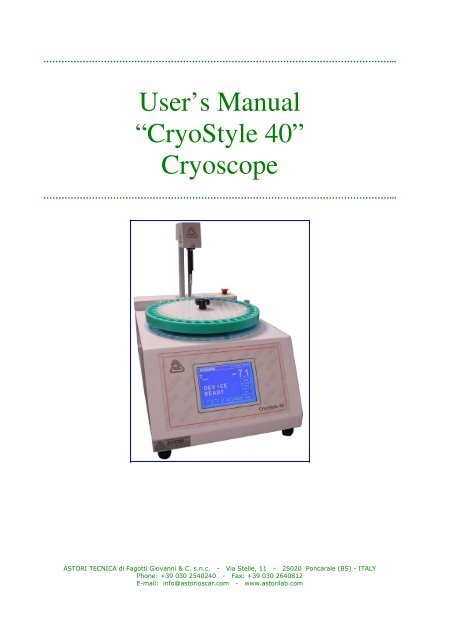
User’s <strong>Manual</strong><br />
<strong>“CryoStyle</strong> <strong>40”</strong><br />
<strong>Cryoscope</strong><br />
……………………………………………………………………………………………………...<br />
ASTORI TECNICA di Fagotti Giovanni & C. s.n.c. - Via Stelle, 11 - 25020 Poncarale (BS) - ITALY<br />
Phone: +39 030 2540240 - Fax: +39 030 2640812<br />
E-mail: info@astorioscar.com - www.astorilab.com
……………………………………………………………………………………………………...<br />
User’s <strong>Manual</strong><br />
<strong>“CryoStyle</strong> <strong>40”</strong><br />
<strong>Cryoscope</strong><br />
……………………………………………………………………………………………………...<br />
WARNINGS ………………………………………………………………………………….....………. 5<br />
FEATURES ………………..............…………………………………………………………………... 5<br />
MECHANICAL FEATURES ………………...............……………………………………….. 5<br />
ELECTRICAL FEATURES …………………………...............……………………………… 5<br />
CLIMATIC FEATURES, STORAGE, PACKAGING AND USE …………….............……. 5<br />
SAFETY DEVICES ………………………….…………………………………………………………. 6<br />
EMERGENCY PUSHBUTTON ……………………………….....……..……………………. 6<br />
INSTALLATION ………………………..………………………………………………………………. 6<br />
SET UP ………………………........................……………………………………………….. 6<br />
FUNCTIONING …………...................………………........................................……….....………. 7<br />
TOUCH SCREEN ……………………………………………………………………………... 7<br />
“DEVICE READY MASK” …………………………………………………………………….. 8<br />
PASSWORD …………………………………………………………………………………… 8<br />
CALIBRATION AND ANALYSIS ………………………………………….………………………….. 9<br />
PREPARATION OF SAMPLES ……………....……………………………………………... 9<br />
ANALYSIS …...……………………………………………………………………………….. 9<br />
CALIBRATION TECHNIQUE …………………………………………………………..…… 11<br />
CALIBRATION ..……………………………………………………………………………… 11<br />
REFERENCE FOR ADDED WATER CALCULATION …………………..............……………… 12<br />
REFERENCE SELECTION ……………..........……………………………………………. 12<br />
MODIFYING THE REFERENCE …………………………………………………………… 13<br />
ALARMS ………………………………………………………………………………………………. 13<br />
2
ALARMS CANCELLATION ...........…………………………………………………………. 13<br />
HOW TO CANCEL THE “SUBST. COOLING LIQUID” ALARM ................................... 14<br />
ADJUSTMENTS ………………………………….....……….……………………………………….. 15<br />
MENU .......................... ……………………………………………………………………………… 15<br />
MAIN MENU ……………….............………………………………………………………… 15<br />
PARAMETERS MENU ………………………………………………………………………. 16<br />
CONFIRMATION MENU ………….....……………………………………………………… 17<br />
MEASUREMENTS MENU ……………………………………………….…………………. 17<br />
BATH MENU ………………………...……………………………………………………….. 18<br />
MOTORS MENU ……..……………………………………………………………………… 18<br />
MANUFACTURER MENU ………………………………………………………………….. 19<br />
MEASUREMENTS MEMORY ………………………………………...……………………. 20<br />
ALARMS MENU ……………………………………………………………………………... 21<br />
STIRRER TEST MENU ……………..........………………………………………………... 22<br />
DISPLAY MENU …………….............………………………………………………………. 23<br />
LANGUAGE MENU …………….....………………………………………………………… 23<br />
Pt100 MENU ................................................................................................................. 24<br />
ANALYSIS MENU ......................................................................................................... 24<br />
SENSORS TABLE ........................................................................................................ 25<br />
PID MENU ..................................................................................................................... 26<br />
TEMP MENU ................................................................................................................. 27<br />
DEBUG ......................................................................................................................... 27<br />
PID TUNING MENU ...................................................................................................... 28<br />
DOWNLOAD MENU ..................................................................................................... 28<br />
KEYBOARD .................................................................................................................. 29<br />
DOWNLOAD MEASUREMENTS …………………..………………………………………………. 30<br />
HOW TO ESTABLISH A CONNECTION ………………………………………..………… 30<br />
TRANSFER MEASUREMENTS ……......………………………………………………….. 34<br />
SAVE MEASUREMENTS …………………………………..…… ………………………… 35<br />
ORDINARY MAINTENANCE ……………….……………………………………………………… 35<br />
CASE CLEANING ………….........………………………………………………………….. 35<br />
FILTER CLEANING ……………...………………………………………………………….. 35<br />
3
DAILY MAINTENANCE ………………………......................................…………………. 35<br />
EXTRAORDINARY MAINTENANCE …………….………………………………………... 35<br />
CHECK AND SUBSTITUTION OF THE COOLING LIQUID ………………….....……… 36<br />
CHECK AND SUBSTITUTION OF THE FILTER ………………...………………………. 36<br />
HOW TO MOVE AND SHIP THE CRYOSCOPE ……...............………………………………… 36<br />
MOVING THE CRYOSCOPE …………….................…………………………………….. 36<br />
SHIPPING THE CRYOSCOPE ……………….........……………………………………… 36<br />
PRINCIPAL COMPONENTS ………...……………………………………………………………… 37<br />
COOLING BATH ………………………………...........................…………………………. 37<br />
HEAD ….....…………………………………………………………………………………… 37<br />
MEASUREMENT THERMISTOR …………………………...……………………………... 38<br />
STIRRER ……………………………………………………………………………………… 38<br />
SPRING …………………………………………………………..............................……… 38<br />
REAR PANEL ……………………………….........................................................……… 39<br />
PRINTER ……………………......……………………………………………………………. 39<br />
PRODUCTS SUPPLIED WITH THE CRYOSCOPE………………………………………………. 40<br />
ACCESSORIES AND CONSUMABLES ...........…………………………………………………... 40<br />
DOCUMENT VALIDITY ……...........………………………………………………………………... 40<br />
WARRANTY ………………….………………………………………………………………………. 40<br />
DISPOSAL …………………………………………………………………………........……………. 41<br />
MENU TABLE ……………………………………………………………………………………....… 42<br />
FUNCTION TABLE ………………………………………………………………………………...… 43<br />
COOLING BATH FORM …………………………………….......................................…………... 45<br />
DECLARATION OF CE CONFORMITY ................................................................................... 46<br />
4
WARNINGS<br />
Before using the equipment read this user guide<br />
This manual is an integral part of the product and must be conserved for future<br />
consultation.<br />
In it you can find important information regarding safety of use and maintenance.<br />
Read carefully the instructions contained in this manual.<br />
This equipment has been realized for the analysis of milk samples or derivatives, for<br />
calibration standard solutions and check solutions for cryoscopy.<br />
Even if this device is provided with protections, the use of the equipment without<br />
following the described procedures could produce a wrong working and damages on the<br />
equipment.<br />
The manufacturer is not liable for damages to people or things caused by improper use<br />
of the equipment and/or not respect of the laws, regulations and instructions described<br />
below.<br />
FEATURES<br />
MECHANICAL FEATURES<br />
- Dimensions: 330 x 375 x 527 mm<br />
- Weight: 26,8 Kg<br />
ELECTRICAL FEATURES<br />
- Electrical supply: 115 V ~ 60 Hz<br />
230 V ~ 50 Hz<br />
- Max. variation of the tension: ±10% of the nominal tension<br />
- Transitory overload: II<br />
- Absorption: 250 W<br />
- Safety fuses: 2 x 2 A, 250 V<br />
CLIMATIC FEATURES, STORAGE, PACKAGING AND USE<br />
- Maximum working temperatures: from 5° to 36°C<br />
- Relative humidity: max. 80% for temperatures up to 31°C, with a linear decrease up to 50% at<br />
a temperature of 36°C.<br />
- Pollution degree: 2<br />
- IP protection grade: 20<br />
5
SAFETY DEVICES<br />
EMERGENCY PUSHBUTTON<br />
The equipment is provided with an emergency pushbutton which interrupts the electrical supply<br />
when a dangerous situation is occurring.<br />
In order to deactivate the safety device turn the pushbutton in the direction of the arrows as<br />
showed in the picture.<br />
INSTALLATION<br />
Avoid placing the equipment near heating sources or windows hit by sunlight.<br />
Place the equipment far from the wall: in this way it would be easier to operate both on the<br />
main switch and on the socket.<br />
The equipment works with 230 V ~ ±10% and a frequency of 50Hz or with 115 V ~ ±10% and a<br />
frequency of 60 Hz.<br />
The electrical socket must supply 3 Ampère continuously.<br />
Check the tension selector located under the equipment: it must be positioned on the<br />
value of the available tension.<br />
According to the electrical safety regulations, check that a good earth connection is<br />
provided. The manufacturer is not liable in case of damage due to a lack of compliance<br />
of this normative.<br />
SET UP<br />
1. Remove the cryoscope from its package: in order to perform this operation correctly, always<br />
hold the equipment by its sides and its lower part with the help of another person.<br />
2. Place it on a perfectly horizontal bench in order to avoid vibrations or movements.<br />
3. Check the tension selector located at the bottom: it must be in the correct position.<br />
The arrow positioned on the selector has to indicate the local tension available. Whether the<br />
position is wrong, rotate the selector by means of a proper screwdriver.<br />
4. Connect the cable to the main socket positioned on the rear of the equipment.<br />
5. Insert the plug in the electrical socket.<br />
6
6. Turn the cryoscope on by pressing the main switch positioned on the back.<br />
7. If the equipment does not turn on, verify that the emergency pushbutton is not pressed. In<br />
this case deactivate it by turning in the direction indicated on the head.<br />
8. Turn the equipment on again.<br />
9. If the equipment does not turn on, check the integrity of the fuses and replace them if<br />
necessary.<br />
10. Turn the equipment on.<br />
11. Wait until the head has completely lifted up and draw the tube.<br />
Pay attention not to hit the reading thermistor.<br />
12. Turn the equipment off.<br />
13. Fill the vessel positioned on the back of the equipment with cooling liquid until the maximum<br />
level indicated. Check that the little pipe collects from the very bottom of the vessel.<br />
14. Turn the equipment on again: the cooling bath will be filled automatically.<br />
15. Wait until the bath reaches the correct working temperature (the display will show the<br />
message EQUIPMENT READY). We suggest to wait at least 10 minutes before proceeding<br />
with the analysis: in this way the equipment could stabilize.<br />
16. Verify that the cryoscope is correctly calibrated by performing 3 analyses of 3 replicates of<br />
standard 0,512°C. In order to perform this operation correctly, fill the tubes with the 0,512°C<br />
check standard until the level of 2,5 ml.<br />
Position the tube inside the duct, then press . Repeat this operation for each sample.<br />
If the result differs for more than ± 0.002°C in relation to the nominal value of the standard,<br />
proceed with the calibration according to the instructions below.<br />
FUNCTIONING<br />
TOUCH SCREEN<br />
The equipment includes the “Touch Screen” system.<br />
Press the buttons that appear on the display to enter the functions and menus.<br />
7
“DEVICE READY” MASK<br />
When “DEVICE READY” appears on the display the measurements or the calibration can start.<br />
The display will show:<br />
11<br />
10<br />
9<br />
1. Date: date, format DD/MM/YY;<br />
2. Time: time, format HH:MM;<br />
3. Bath Temp: temperature of the cooling bath;<br />
4. PSW: it enters the password menu;<br />
5. Type: it enters the milk reference value;<br />
6. Cal.: it enters the calibration menu;<br />
7. Menu: it returns to the main menu;<br />
8. Start: it starts the analysis;<br />
9. : it rotates the carousel;<br />
10. ↑: it lifts the head;<br />
11. ↓: it lowers the head.<br />
PASSWORD<br />
The equipment includes a password to block the setting functions to unauthorized operators.<br />
Without password, only a few functions are accessible.<br />
The password default value is ; at the moment of installation all the functions are accessible<br />
without password.<br />
The password value can be changed anytime by the person in charge in the laboratory by<br />
pressing “Password” and inserting the current value; then enter the function “New Password”<br />
and digit the new value.<br />
The calibration procedure is not covered by any identification code (password).<br />
1<br />
2<br />
3<br />
4<br />
5<br />
6<br />
7<br />
8<br />
8
1. Password: it enters the current password value.<br />
2. New Password: it enters the new password value.<br />
3. Esc: it returns to the “Device Ready” mask.<br />
CALIBRATION AND ANALYSIS<br />
PREPARATION OF SAMPLES<br />
Milk:<br />
1. Analyze only fresh milk samples without preservatives.<br />
2. The samples temperature must be between 15°C and 30°C.<br />
3. Do not analyze cool milk samples.<br />
4. Turn the vessel upside down several times avoiding the formation of bubbles.<br />
Creams:<br />
1<br />
2<br />
3<br />
1. Analyze only fresh cream samples.<br />
2. Before proceeding the analysis, heat the cream sample up to 30°C, let it cool down until it<br />
reaches the room temperature and mix it constantly.<br />
ANALYSIS<br />
1. Before performing the analysis, clean the stirrer and the thermistor by using a soft piece of<br />
paper.<br />
2. Be sure that the tubes are completely dry and clean. Do not use tubes not recommended by<br />
the manufacturer.<br />
3. Be sure that the display indicates the message: “EQUIPMENT READY”.<br />
4. Fill the tubes with 2,5 ml of samples.<br />
5. Place the tubes in the holes of the carousel and press .<br />
9
Then the display will show the following curve:<br />
1. Sample number;<br />
2. Analysis curve;<br />
3. STOP: it interrupts the analysis;<br />
4. Kind of milk;<br />
5. Rif.: water reference value;<br />
6. Menu: it returns to the main menu.<br />
When a sample analysis finishes, the display will show:<br />
4<br />
1<br />
2<br />
3<br />
1<br />
2<br />
3 6<br />
4<br />
5<br />
5<br />
6<br />
7<br />
8<br />
10
1. Ref.: water reference value;<br />
2. Analysis result (in mC or mH);<br />
3. STOP: it stops the analysis;<br />
4. Reset: it cancels the alarm (if an alarm is on);<br />
5. Date: date;<br />
6. Time: time;<br />
7. Percentage of added water;<br />
8. Menu: it enters the main menu.<br />
CALIBRATION TECHNIQUE<br />
1. Before using a standard solution, gently turn its bottle upside down and rotate it several<br />
times to mix its content thoroughly. Pay attention not to shake it and avoid the formation of<br />
bubbles. The standard solutions should not be used from bottles that are less than one quarter<br />
full. Gently wipe the thermistor and the stirrer downwards only by using a soft piece of paper.<br />
2 Calibration procedure: it is warmly suggested to average the readings of 3 replicates of each<br />
standard. The accuracy should be better than ± 0.002°C. Any first reading may be incorrect, for<br />
this reason do not consider the first value.<br />
3. A re-calibration should be carried out in the following cases: when there is a high variability<br />
among the samples analyzed; anytime the thermistor is replaced or if any mistake could be<br />
occurred during the calibration procedure.<br />
4. When the calibration procedure has been correctly achieved, it is possible to check the<br />
accuracy of the curve by measuring the control solution (-0,512°C ± 0,002°C) or both the<br />
calibration standard solutions.<br />
CALIBRATION<br />
Analyze at least 3 replicates of the -0,408°C standard. Check the repeatability (± 0,002°C) of<br />
the results as they are displayed. If the repeatability looks correct, press in order to<br />
calibrate these measured values.<br />
The display will show:<br />
1<br />
2<br />
3 5<br />
4<br />
11
1. Cal. A –0.408: it confirms the calibration (–0.408°C);<br />
2. Cal. A –0.600: it confirms the calibration (–0.600°C);<br />
3. Reset A: it resets the calibration;<br />
4. Actual digital values;<br />
5. Esc: it returns to the “Device Ready” mask.<br />
Confirm the calibration by pressing the key associated to the reference value.<br />
The equipment memorizes the last read value.<br />
Proceed with the same operation with the standard -0.600°C.<br />
REFERENCE FOR ADDED WATER CALCULATION<br />
REFERENCE SELECTION<br />
Before processing the measurement it is possible to select the kind of milk. In this way the<br />
added water reference value will be modified according to the milk you need to analyze.<br />
In order to select the milk, press the button.<br />
1<br />
2<br />
3<br />
4<br />
5<br />
6 7<br />
1. Cow: cow milk;<br />
2. Sheep: sheep milk;<br />
3. Goat: goat milk;<br />
4. Buffalo: buffalo milk;<br />
5. Other: other kind of milk;<br />
6. Esc: it returns to the “Device Ready” mask;<br />
7. Modify: it modifies the water reference value.<br />
Note that the selected type of milk is marked in bold.<br />
12
MODIFYING THE REFERENCE<br />
1<br />
2<br />
1. Types of milk;<br />
2. Esc: it returns to the previous menu;<br />
3. Current values.<br />
ALARMS<br />
In case an alarm situation occurs, the message “ALARM” appears on the top of the display<br />
along with a message indicating the operation necessary to cancel this message. The word KO<br />
will appear in bold in correspondence to the active alarm.<br />
The alarms are always accompanied also by an acoustic signal.<br />
ALARMS CANCELLATION<br />
The alarm signals can be erased by pressing the reset button located in the panel showing the<br />
analysis results or inside the alarm menu.<br />
1<br />
2<br />
3<br />
3<br />
13
1. Alarm condition;<br />
2. Alarm message (in negative);<br />
3. Reset: It allows to cancel alarm.<br />
HOW TO CANCEL THE “SUBST. COOLING LIQUID” ALARM<br />
It is quite different to cancel the “Subst. Cooling Liquid” alarm: in fact it is necessary to set it<br />
again. Please proceed as described in the following paragraph.<br />
Replace the cooling liquid contained in the plastic bottle located behind the equipment.<br />
Follow the path displayed on the screen: menu bath press the “cooling liquid” button<br />
which will turn negative.<br />
Turn the cryoscope off and on again.<br />
During the substitution of the cooling liquid clean the filter, or replace it if necessary.<br />
14
ADJUSTMENTS<br />
It is possible to make an amplitude regulation of the stirrer (freezing stroke) by turning the<br />
trimmer behind the equipment.<br />
To unlock the trimmer, please rotate the locking system anticlockwise.<br />
Increase or decrease the stirrer strength by rotating in a clockwise or anticlockwise direction.<br />
When the stirring power is properly adjusted, lock the trimmer again.<br />
2<br />
1. Locking system<br />
2. Trimmer<br />
MENU<br />
MAIN MENU<br />
1<br />
2<br />
3<br />
4<br />
1<br />
1. Parameter: it enters the parameter menu;<br />
2. Bath: it shows the cooling bath menu;<br />
3. Manufact.: menu reserved to the Service Dept.;<br />
4. Alarms: it enters the alarms menu;<br />
5. Measures: It includes sensors data and parameters;<br />
6. Motors: it shows the motor menu;<br />
7. Memory: it enters the measurements memory;<br />
8. Esc :it returns to the “Device Ready” mask;<br />
5<br />
6<br />
7<br />
8<br />
15
PARAMETERS MENU<br />
This menu is composed by two pages:<br />
1<br />
2<br />
3<br />
4<br />
5 8<br />
9<br />
10<br />
11<br />
12<br />
13<br />
1. S. Tubes N.: it modifies the size of the analysis batch (Maximum 40);<br />
2. Stirrer Test: it enters the “Stirrer Test” menu;<br />
3. Pump Test: it refills the cooling bath and checks the pump;<br />
4. Prn Param: it prints some technical parameters;<br />
5. Esc: it returns to the main menu;<br />
6. Actual values;<br />
7. Test Up/Dw: this function is reserved to the Service Dept.;<br />
8. Next: it scrolls to the next page;<br />
9. Scale: it modifies the measurement unit: -°C - °H;<br />
10. Language: it modifies the language;<br />
11. Display: it shows the display menu;<br />
12. Default Par.: it erases all settings;<br />
N.B.: Do not modify this parameter.<br />
(The modification of this parameter may erase ALL the setting data related to the<br />
equipment);<br />
13. Esc: it returns to the previous page.<br />
6<br />
6<br />
7<br />
16
CONFIRMATION MENU<br />
To avoid to perform unwilling modifications to the equipment settings, some functions ask for a<br />
further confirmation.<br />
1 2<br />
3<br />
1. OK: it confirms the previous operation;<br />
2. Cancel: it cancels the previous operation;<br />
3. Esc: it returns to the previous menu;<br />
MEASUREMENT MENU<br />
1<br />
2<br />
3<br />
4<br />
1. Pt100: it includes the parameters of the bath probe;<br />
2. Analysis: it includes the reading thermistor parameters;<br />
3. Sensors: it shows sensors data and the parameters related to the A/D converters;<br />
4. Esc: it returns to the previous menu.<br />
17
BATH MENU<br />
1<br />
2<br />
3<br />
4<br />
1. PID: it modifies the control parameters of the cooling bath;<br />
2. Temp.: it modifies the temperature of the cooling bath;<br />
3. Cooling L.: it removes the alarm related to the substitution of the cooling liquid;<br />
4. Esc: it returns to the main menu.<br />
MOTORS MENU<br />
This menu is composed by two pages:<br />
1<br />
2<br />
3<br />
4<br />
5<br />
6<br />
18
7<br />
8<br />
9<br />
10<br />
11<br />
12 13<br />
1. Duration T. s: pump activation time between two analyses;<br />
2.Duration Man. s: start-up pump activation time;<br />
3. Start Flag: pump automatic activation;<br />
4. Esc: it returns to the main menu;<br />
5. Actual values;<br />
6. Next: it scrolls to the next page;<br />
7. Tubes N max.: max tubes number available on the carousel;<br />
8. Micro Step: it indicates the time between two microsteps;<br />
9. Step Delay: it indicates the time needed to reach a tube before analysis;<br />
10. Low Power: it indicates the minimum voltage applied to the carousel while maintaining its<br />
position;<br />
11. High Power: it indicates the minimum voltage applied to the carousel while rotating;<br />
12. Pag. Prec.: it returns to the previous page;<br />
13. Test Step: it rotates the carousel, press this button once more in order to interrupt the<br />
rotation.<br />
MANUFACTURER MENU<br />
1<br />
2<br />
3<br />
4<br />
5<br />
5<br />
19
1. Update: it updates the cryoscope software;<br />
2. Serial N.: it indicates the serial number of the cryoscope;<br />
3. Prn Config: it prints the cryoscope configuration;<br />
4. Debug: it shows the actual functioning and the situation of some relevant fields;<br />
5. Esc: it returns to the main menu.<br />
MEASUREMENTS MEMORY<br />
1<br />
2 5<br />
3<br />
1. Measurement raw<br />
2. Data: by entering this parameter it is possible to download the data on a computer or erase<br />
the measurements archive (see Download menu);<br />
3. Next: it scrolls to the next page of measuring memory;<br />
4. Prev: it scrolls to the previous page of measuring memory;<br />
5. Esc: it returns to the main menu.<br />
Every measurement is stored in memory according to the following scheme:<br />
N. of sample Date - Time Analysis Result % H2O<br />
4<br />
20
ALARMS MENU<br />
1<br />
3<br />
1. Alarms list:<br />
- Temp. Bath: insufficient temperature inside the bath;<br />
- Tube: tube not detected after analysis;<br />
- Database Full: database full;<br />
- Cooling Liq:: replace the cooling liquid (see “Alarm” paragraph Alarms Cancellation);<br />
- CRC Memory: wrong values in memory;<br />
- A/D Error: error in the analogical / digital system conversion;<br />
- Memory Flash: error during data writing;<br />
- Head Motor: motor problem.<br />
2. Warnings List:<br />
- Time Out: the analysis runs out of time;<br />
- Data Flash: memory warning.<br />
3. Esc: it returns to the main menu;<br />
4. Reset: it cancels the alarms.<br />
2<br />
4<br />
21
STIRRER TEST MENU<br />
This menu is composed by two pages:<br />
1<br />
2<br />
3<br />
7<br />
8<br />
9<br />
10<br />
11<br />
1. Agitation: it adjusts the agitation force;<br />
2. Stirrer: it adjusts the stirrer force;<br />
3. Esc: it returns to the previous menu;<br />
4. Test: it makes tests on the agitation and freezing stroke;<br />
5. Present values;<br />
6. Next: it scrolls to the next page;<br />
7. Frequency: frequency of the wave shape on the stirrer;<br />
8. # Sin.: number of approximation steps of the wave shape;<br />
9. Type Wave: kind of wave on the stirrer;<br />
10. Wave Off: number of not executed approximation steps;<br />
11. Prev: it returns to the previous page.<br />
5<br />
4<br />
4<br />
5<br />
6<br />
22
DISPLAY MENU<br />
1<br />
2<br />
3<br />
4<br />
5<br />
1. Contrasts: it shows the contrast of the display;<br />
2. Date: it shows the date in the DD/MM/YY format;<br />
3. Hour: it shows the time in the HH:MM format;<br />
4. Prn T Bridge: it prints the temperature on the checking bridge of the cooling bath;<br />
5. Esc: it returns to the previous menu;<br />
6. Present values.<br />
LANGUAGE MENU<br />
1<br />
2<br />
3<br />
4<br />
1. Italian<br />
2. English<br />
3. French<br />
4. Esc: it returns to the previous menu.<br />
The marked language value has to be considered as the selected one from the operator.<br />
After modifying the language, it is necessary to turn the equipment off and on in order to make<br />
the modification valid.<br />
6<br />
23
Pt100 MENU<br />
1<br />
2<br />
3<br />
4<br />
1. Temp. –10 C: it shows the pt100 probe calibration values;<br />
2. Temp. +10 C: it shows the pt100 probe calibration values;<br />
3. Offset: pt100 probe temperature offset;<br />
4. Esc: it returns to the previous menu;<br />
5. Get: it acquires the value;<br />
6. Actual values.<br />
ANALYSIS MENU<br />
1<br />
2<br />
3<br />
4<br />
5<br />
1. Linearity: it shows the linearity of the reading channel;<br />
2. Duration: it shows the reading time (duration of the plateau);<br />
3. Dig. Filter: filter applied to the read value;<br />
4. Floating Mean: number of data which can be filtered;<br />
5. Esc: it returns to the previous menu;<br />
6. Present values.<br />
5<br />
5<br />
6<br />
6<br />
24
SENSORS TABLE<br />
1<br />
2<br />
3<br />
4<br />
5<br />
1. n A: read value from A/D converters on channel A;<br />
2. n B: read value from A/D converters on channel B (disabled function on CryoStyle 40);<br />
3. n Bath: read value from pt100 sensor;<br />
4. UP DW: values of microswitches;<br />
5. Esc: it returns to the previous menu;<br />
6. T: nA value converted in temperature;<br />
7. T: nB value converted in temperature;<br />
8. T Bath: present temperature of the cooling bath;<br />
9. FCA FCB: photoelectric cells condition.<br />
6<br />
7<br />
8<br />
9<br />
25
PID MENU<br />
This menu is composed by two pages:<br />
1<br />
2<br />
3<br />
4<br />
5<br />
6<br />
9<br />
10<br />
11<br />
12<br />
13<br />
1. Cycle Time [ms]: reading time of the bath temperature for checking;<br />
2. K Proportional: constant of the proportional check;<br />
3. Integral T [s]: time constant of the integral check;<br />
4. Derivative T [s]: time constant of the derivative check;<br />
5. Tau Filter: constant of time and filter;<br />
6. Prev.: it returns to the previous menu;<br />
7. Present values;<br />
8.Next: it scrolls to the next page;<br />
9. PWR Min: power provided by the regulator in minimal supply condition (in percentage);<br />
10. PWR Max: power provided by the regulator in maximal supply condition (in percentage);<br />
11. PWM Type: kind of bath control;<br />
12. PID Tuning: cooling bath calibration (function reserved to the Service Dept.);<br />
13. Pag. Prec.: it returns to the previous page.<br />
7<br />
8<br />
7<br />
26
TEMP MENU<br />
1. Set Point: it indicates the Set Point temperature of the cooling liquid;<br />
2. Temp. Alarm: it indicates the alarm temperature of the cooling bath;<br />
3. Temp. Start: it indicates the cooling bath temperature under which the message<br />
“EQUIPMENT READY” appears;<br />
4. Bridge T. Max: max bridge temperature before the detachment;<br />
5. Bridge Prot.: it activates the protection from the control bridge;<br />
6. Esc: it returns to the previous menu;<br />
7. Actual values.<br />
DEBUG<br />
1<br />
2<br />
3<br />
4<br />
5<br />
6<br />
1<br />
2<br />
1. State machine condition.<br />
2. Microswitches conditions.<br />
7<br />
27
PID TUNING MENU<br />
1. Tuning: it starts the automatic calibration of the cooling bath;<br />
2. Esc: it returns to the previous menu;<br />
3. Present power of the cooling bath control system;<br />
4. Present bath temperature.<br />
DOWNLOAD MENU<br />
1<br />
2<br />
1 2<br />
3<br />
1. Download: It downloads data (see download measurements → transfer measurements );<br />
2. Cancel: It erases data;<br />
3. Esc: it returns to the memory.<br />
3<br />
4<br />
28
KEYBOARD<br />
1<br />
2<br />
3<br />
1. Min: minimum admitted value<br />
2. Name: parameter name<br />
3. Buttons: keyboard<br />
4. Max: maximum admitted value<br />
5. Present value<br />
6. New value<br />
7. Esc: it returns to the previous menu<br />
8. CANC: it erases the inserted value<br />
9. OK: it confirms the inserted number<br />
4<br />
5<br />
6<br />
7<br />
8<br />
9<br />
29
DOWNLOAD MEASUREMENTS<br />
It is possible to download the measurements memory from the equipment to a computer.<br />
The following chapters describe the procedure to establish a connection, the procedure to<br />
transfer data and the procedure to save the measurements.<br />
HOW TO ESTABLISH A CONNECTION<br />
The CryoStyle – Computer connection that we tested and approved was based on a IBM-PC<br />
system. The Operating System was WindowsXP ® . All the following pictures and instructions<br />
refer to this OS.<br />
The PC must have a COM1 or COM2 port, never use a COM3 port.<br />
From Windows ® “Start Menu”, click on “Hyper Terminal” software link and proceed how<br />
explained in the following images:<br />
30
After opening the HyperTerminal program, a window will appear, asking for a confirmation:<br />
Confirm by clicking “Yes”.<br />
A new window will appear. Insert the connection name and select the related icon (the one you<br />
like most).<br />
31
After inserting the information required, confirm by pressing “OK”; then a new window asking<br />
”Connect to...” will appear on the display.<br />
Select the COM port that you decide to use for the connection.<br />
When a COM port is selected, all other voices become inactive.<br />
Confirm by pressing ”OK”.<br />
Check that all voices of the new window are identical to the ones in the picture showed here<br />
below.<br />
Confirm by clicking “OK”.<br />
Now, only one window is displayed.<br />
32
To save the connection, close the program. A new window (“Disconnect Now?”) will be shown.<br />
Confirm by clicking “Yes”.<br />
You will be asked to save the connection, click “Yes” to confirm.<br />
33
A new connection has been established. To check if the new connection has been stored,<br />
follow the path as showed in the picture here below.<br />
The described connection procedure has to be done the very first time, only.<br />
To connect the equipment with the PC, just recall the existing connection (see the following<br />
paragraph).<br />
TRANSFER MEASUREMENTS<br />
Recall the existing connection by following the picture here below:<br />
The “Hyper Terminal” program will start automatically with the name of the connection.<br />
Connect the cable from the “COMPUTER” output of the CryoStyle 40 to the COM serial input of<br />
the PC. Now, on the CryoStyle menu, follow this path: menu memory Data Download.<br />
By means of the “Hyper Terminal” window, every measurement contained inside the equipment<br />
memory will be transferred to the PC.<br />
34
SAVE MEASUREMENTS<br />
To save measurements, create a new text file (with “NotePad” or “WordPad”) into a new folder<br />
which will be used by the operator to store all the measurements data.<br />
Click on “Copy” from the “Modify” menu of “Hyper Terminal” in order to select the<br />
measurements to be saved.<br />
Open the text file where you want to save the measurements, then click on “Paste” from the<br />
“Modify” menu of the “text file”.<br />
When the data are copied, save the file: click “Save” from the “File” menu of the “text file”.<br />
ORDINARY MAINTENANCE<br />
CASE CLEANING<br />
Before starting the cleaning process, always unplug the equipment from the electrical<br />
connection. Do not pour water on the equipment, but use a dump cloth instead.<br />
Clean the equipment with a neutral detergent.<br />
Do not use alcohol or aggressive detergents to clean the equipment.<br />
FILTER CLEANING<br />
In order to clean the filter, proceed as follows:<br />
1. Disconnect the filter from the pipes which connect it to the cryoscope;<br />
2. Let warm water flow inside the filter in the opposite direction than the one indicated by the<br />
arrow located on the filter.<br />
3. Repeat this operation several times.<br />
4. Connect the filter paying attention to its direction. When it is in the correct position, the arrow<br />
will indicate the top.<br />
DAILY MAINTENANCE<br />
1. Dry the wet parts thoroughly, absorbing all the cooling liquid;<br />
2. Clean and dry the mandrel;<br />
3. Check and restore the cooling liquid level, if necessary;<br />
4. Check and replace the filter, if necessary;<br />
5. If any sediment appears in the cooling liquid, please replace it (clean the bottle, as well)<br />
along with its filter.<br />
EXTRAORDINARY MAINTENANCE (“SUBSTITUTION OF LIQUID”)<br />
The equipment will inform through an alarm message when a substitution of cooling liquid is<br />
needed. Proceed with its substitution. In order to erase the error message proceed as<br />
described in: Alarms How to cancel the “Subst. Cooling Liquid” alarm.<br />
We warmly suggest to subscribe a yearly maintenance agreement with our local Service<br />
Centre for a complete cleaning operation to the heat exchangers and a general check of<br />
the good condition of the electric and electronic parts.<br />
In this way, you can prevent more serious damages to the equipment.<br />
Every maintenance operation which is not mentioned in this manual must be carried out<br />
by qualified personnel authorized by the manufacturer.<br />
35
CHECK AND SUBSTITUTION OF THE COOLING LIQUID<br />
Check the level and the clearness of the liquid every day.<br />
Replace the cooling liquid in one of the following situations:<br />
- after a breakage of a tube containing milk inside the bath duct;<br />
- when the liquid becomes turbid;<br />
- when some sediment is present on the bottom of the liquid tank;<br />
- when the filter is dirty.<br />
Refill the tank paying attention not to exceed the indicated quantity.<br />
After replacing the liquid, check the position of the waste tube as it has to be over the<br />
maximum level indicated.<br />
CHECK AND SUBSTITUTION OF THE FILTER<br />
Check the filter condition every day.<br />
The filter cleaning is necessary in one of these situations:<br />
- if the message: “Subst. Cooling Liquid” appears on the display;<br />
- whenever the filter is dirty.<br />
Replace the filter after cleaning it a few times.<br />
HOW TO MOVE AND SHIP THE CRYOSCOPE<br />
MOVING THE CRYOSCOPE<br />
Every time you need to move the equipment inside your laboratory, pay attention to maintain it<br />
in horizontal position in order to avoid a liquid loss.<br />
Always hold the equipment by its sides and its lower part with the help of another person.<br />
SHIPPING THE CRYOSCOPE<br />
In case you need to ship the equipment proceed as follows:<br />
1. Turn it off;<br />
2. Empty the vessel containing the cooling liquid located on the back of the equipment;<br />
3. Vacuum the liquid which remains inside the bath by means of a syringe;<br />
4. Turn the equipment on;<br />
5. Wait around 60 seconds in order to complete the emptying of the automatic refilling system;<br />
6. Vacuum the liquid inside the bath again;<br />
7. Place an empty tube inside the duct;<br />
8. Lower the head by pressing the button.<br />
9. When shipping the cryoscope, use the original package or a sturdy box and fill the empty<br />
spaces with foam polystyrene.<br />
36
PRINCIPAL COMPONENTS<br />
COOLING BATH<br />
The bath is cooled by means of a Peltier cell at –7°C +/- 0.5°C .<br />
HEAD<br />
The head mechanism contains the stirrer solenoid, the sample-tube mandrel along with the<br />
thermistor and the stirrer.<br />
1<br />
2<br />
3<br />
5<br />
1. Head<br />
2. Mandrel<br />
3. Stirrer<br />
4. Thermistor<br />
5. Carousel<br />
4<br />
37
MEASUREMENT THERMISTOR<br />
The thermistor is the most fragile part of the equipment, its glass part must not be touched.<br />
It must be positioned in order to keep the temperature sensor at the same precise distance<br />
from the walls and from the bottom of the test tube.<br />
STIRRER<br />
It must be located in a central position within the mandrel slot and must be free to symmetrically<br />
vibrate from the axis of the thermistor.<br />
SPRING<br />
Inside the cooling bath there is the spring.<br />
Pay attention to its correct position, which must be exactly like in the picture below.<br />
The spring must be at the same level of the bath duct.<br />
If the spring is over the duct, it will probably be dragged by the tubes.<br />
If the spring is too low, it will probably prevent the carousel rotation.<br />
SMALL<br />
DIAMETER<br />
LARGE<br />
DIAMETER<br />
38
REAR PANEL<br />
1<br />
2<br />
3<br />
4<br />
1. Filter<br />
2. Trimmer<br />
3. Data input<br />
4. Printer serial port<br />
5. Automatic refilling tube<br />
6. Exhaust tube<br />
7. Main switch and fuses compartment<br />
8. External pump<br />
9. Cooling liquid tank<br />
PRINTER<br />
It prints the following data, sample by sample:<br />
1. the cryoscopic temperature;<br />
2. the % of added water calculated according to the given reference value in function 2 (H2O<br />
reference).<br />
Paper feeding:<br />
Press the “feed” key located on the right side of the front panel of the printer.<br />
5<br />
6<br />
7<br />
8<br />
9<br />
39
Change the paper roll:<br />
In order to change the paper roll proceed as follows:<br />
1. open the plastic cover;<br />
2. remove the old roll;<br />
3. place the new roll in the holder, by positioning the beginning part towards the front of the<br />
printer;<br />
4. insert the sheet of paper into the feeding slot which is located in the upper part of the cover,<br />
then push the “feed” key to unroll the paper out of the printer;<br />
5. before closing the cover, pull the paper through its slot.<br />
PRODUCTS SUPPLIED WITH THE CRYOSCOPE<br />
Every time we provide a cryoscope, we always supply a “starter kit” in order to make our<br />
customers able to operate immediately after the installation:<br />
- 4 boxes of calibrated glass test tubes 2-2,5 ml, 12 pcs each<br />
- 1 stainless steel tube holder, 50 places<br />
- 1 standard for cryoscopy check, 0,512°C, 250 ml<br />
- 1 standard for cryoscopy calibration, 0,408°C, 250 ml<br />
- 1 standard for cryoscopy calibration, 0,600°C, 250 ml<br />
- 1 cooling liquid, 250 ml<br />
- EP-50 thermal printer<br />
ACCESSORIES AND CONSUMABLES<br />
- 2-2,5 ml precision micropipette (code 67226)<br />
- Disposable plastic tips for 2/2,5 ml pipette, 1000 pcs. (code 37470)<br />
- Calibrated glass samples tubes for cryoscopy, 12 pcs. (code 67205)<br />
- 24-place ABS plastic tube holder (code 67251)<br />
- Standard for cryoscopy check 0,512°C, 250ml (code 63220)<br />
- Standard for cryoscopy calibration 0,408°C, 250ml (code 63215)<br />
- Standard for cryoscopy calibration 0,600°C, 250ml (code 63225)<br />
- Cooling liquid for bath, 1 liter (code 67210)<br />
- Cooling liquid for bath, 250 ml (code 67200)<br />
- Thermal printer paper roll (code 67219)<br />
DOCUMENT VALIDITY<br />
ASTORI TECNICA reserves the right to review and modify this document without any notice<br />
(any variation will not affect the respect of the directives).<br />
WARRANTY<br />
The warranty for the cryoscope covers a period of 12 months from the date of purchase.<br />
We recommend the use of original test tubes, cooling liquid, and other spare parts; a failure to<br />
use them may invalidate the warranty.<br />
THE WARRANTY DOES NOT INCLUDE THE MEASUREMENT THERMISTOR.<br />
40
DISPOSAL<br />
The symbol of the crossed garbage collector indicates that the product at the end of<br />
its useful life should be collected separately from normal garbage.<br />
The user will give the equipment, at the end of its usage, to centers for collection of<br />
electronic and electro technical garbage according to rules and laws.<br />
The proper collection of the disused equipment, the recycling, the treatment and disposal<br />
contribute to avoid possible negative effects on the environment and human health,<br />
encouraging the recycling of the materials that compose the equipment.<br />
41
MENUS TABLE<br />
S. TUBES NUMBER<br />
STIRRER TEST<br />
PUMP TEST<br />
AGITATION<br />
STIRRER<br />
FREQUENCY<br />
# SIN<br />
TYPE WAVE<br />
WAVE OFF<br />
PARAMETER PRINT PARAM<br />
TEST UP/DW<br />
SCALE<br />
LANGUAGE<br />
ITALY<br />
ENGLISH<br />
FRENCH<br />
CONTRAST<br />
DISPLAY DATE<br />
HOUR<br />
PRN T BRIDGE<br />
DEFAULT PAR.<br />
TEMP –10<br />
CONFIRM<br />
PT100 TEMP +10<br />
OFFSET<br />
LINEARITY<br />
ANALYSIS DURATION<br />
MEASURES DIG. FILTER<br />
FLOATING MEAN<br />
A/D CONVERTERS<br />
SENSORS TEMPERATURES<br />
MICROSWITCH<br />
PHOTOELECTRIC<br />
CYCLE TIME<br />
K PROPORTIONAL<br />
INTEGRAL T.<br />
PID DERIVATIVE T.<br />
TAU FILTER<br />
PWR MIN<br />
PWR MAX<br />
BATH PWM TYPE<br />
MAIN PID TUNING<br />
SET POINT<br />
TEMP. ALARM<br />
AUTOTUNING<br />
TEMP.<br />
COOLING L.<br />
TEMP. START<br />
BRIDGE T. MAX<br />
BRIDGE PROT.<br />
DURATION T. S<br />
PUMP DURATION MAN T<br />
START FLAG<br />
TUBES N MAX<br />
MOTORS MICRO STEP<br />
CAROUSEL<br />
UPDATE<br />
STEP DELAY<br />
LOW POWER<br />
HIGH POWER<br />
TEST STEP<br />
MANUFACT. SERIAL N.<br />
PRN CONFIG<br />
DEBUG<br />
DATA DOWNLOAD<br />
MEMORY NEXT<br />
PREV<br />
TEMP. BATH<br />
TUBES<br />
DATABASE FULL<br />
ALARMS PID<br />
CRC MEMORY<br />
ALARMS A/D ERROR<br />
MEMORY FLASH<br />
HEAD MOTOR<br />
WARNINGS<br />
RESET<br />
TIME OUT<br />
DATA FLASH<br />
42
PASSWORD<br />
PASSWORD<br />
NEW PASSWORD<br />
CAL. – 0.408<br />
CAL. CAL. – 0.600<br />
RESET CONFIRM<br />
COW<br />
SHEEP<br />
TYPE GOAT<br />
BUFFALO<br />
OTHER<br />
MODIFY<br />
FUNCTIONS TABLE<br />
# SIN Feet number to round up the wave trace<br />
A/D ERROR<br />
AD CONVER<br />
Analogical / digital conversion system problem<br />
TERS Data read by AD converters<br />
AGITATION Regulation of the agitation<br />
AUTOTUNING Automatic regulation of the cooling bath<br />
BRIDGE PROT. It activates the protection of the control bridge<br />
BRIDGE T. MAX Max. bridge temperature before take off<br />
CANCEL It erases the measurements memory<br />
CONFIRM It confirms the last operation<br />
CONTRAST It indicates the display contrast<br />
COOLING L. It allows to cancel the “Cooling Liquid” alarm<br />
CRC MEMORY Memorization of set failed data<br />
CYCLE TIME Reading time of the bath temperature for its check<br />
DATABASE FULL Measurements database full<br />
DATE Date showed in DD/MM/YY format<br />
It shows the actual functioning and the condition of some relevant<br />
DEBUG variables<br />
DERIVATIVE T. Constant of derivative time control<br />
DIG. FILTER Filter on reading value<br />
DOWNLOAD It downloads the measurements memory<br />
DURATION Reading time<br />
DURATION MAN pump parameter<br />
DURATION T S pump parameter<br />
ENGLISH Language selection<br />
ESC It returns to the previous menu<br />
FLOATING MEAN analysis parameter<br />
FRENCH Language selection<br />
FREQUENCY Frequency of the wave shape on the stirrer<br />
HEAD MOTOR Head motor problem<br />
HIGH POWER Max. tension applied to the plate (rotation)<br />
HOUR Time showed in HH:MM format<br />
INTEGRAL T Constant of integral time control<br />
ITALY Language selection<br />
K PROPORTIONAL Constant of proportional time control<br />
LINEARITY Linearity of the reading channel<br />
43
LOW POWER Min. tension applied to the plate (position)<br />
MEMORY FLASH Error during the writing of the setting data<br />
MICRO STEP Indicates the time between two microsteps<br />
MICROSWITCHES microswitches condition<br />
NEW PASSWORD It inputs the new password value<br />
NEXT Next page<br />
OFFSET Pt100 temperature probe offset<br />
PASSWORD It inputs the password value<br />
PHOTOELECTRIC CELLS Actual photoelectric cells condition<br />
PID TUNING Cooling bath calibration<br />
PREV. Previous page<br />
PRN CONFIG It prints the configuration of the equipment<br />
PRN PARAM It prints data related to the sensors (pt100) and converters<br />
PRN T BRIDGE It prints the temperature on the check bridge of the cooling bath<br />
PUMP TEST It refills the cooling bath<br />
PWM TYPE Check parameter<br />
PWR MAX Max. power of the PID check (%)<br />
PWR MIN Min. power of the PID check (%)<br />
RESET It allows to cancel alarms<br />
S. TUBES N analysis batch size (Maximum 40)<br />
SCALE Measurement unit (°C - °H)<br />
SERIAL N. Serial number of the cryoscope<br />
SET POINT Set point temperature of the bath<br />
START FLAG pump parameter<br />
STEP DELAY Time needed for searching the next tube on the carousel<br />
STIRRER It adjusts the freezing stroke<br />
TAU FILTER Time constant of the filter<br />
TEMP +10 Pt100 probe calibration values<br />
TEMP -10 Pt100 probe calibration values<br />
TEMP. ALARM Alarm temperature of the bath<br />
TEMP. BATH Alarm for insufficient temperature of the bath<br />
TEMP. START Temperature of the bath (equipment ready)<br />
TEMPERATURES Actual value of the temperatures<br />
TEST STEP It rotates the carousel<br />
TEST UP/DW By pressing Start from the main display, the up/down test starts<br />
TIME OUT The analysis is out of time<br />
TUBE Number of tube available for analysis<br />
TUBES N MAX Analysis batch size (Maximum 40)<br />
TYPE WAVE It indicates the kind of wave on the stirrer<br />
UPDATE It updates the software version<br />
WAVE OFF Number of non-executed approximation steps<br />
44
COOLING BATH FORM<br />
Assembling date:__________________ Testing date:_____________<br />
Serial number:__________________ Testing surveyor: Mr. Rampini Paolo<br />
Notes:<br />
NOTE: this form is an essential part of the bath and must always be kept with it.<br />
If returned for any damage without this form, the repairs and the replacement under warranty<br />
conditions will not be possible. In this case the manufacturer reserves the right to apply the<br />
warranty conditions or not.<br />
Astori Tecnica S.n.C.<br />
_____________________<br />
45
Dichiarazione di conformità<br />
Declaration of conformity<br />
Costruttore / Manufacturer: ASTORI TECNICA di Fagotti Giovanni & C. S.n.c.<br />
Via Stelle n. 11 – 25020 Poncarale (BS) – Italy<br />
Strumento / Equipment: Crioscopio - <strong>Cryoscope</strong><br />
Modello / Model: CryoStyle 40<br />
Matricola n. / Serial number:<br />
Anno di fabbricazione / Year of manufacturing:<br />
Il sottoscritto, legale rappresentante della ditta Astori Tecnica Snc, dichiara che i prodotti<br />
sopraccitati sono conformi alle seguenti direttive: 2004/108/CE (ex 89/ 336 CEE) e 2006/95/CE<br />
(ex 73/ 23 CEE) ed alle norme EN 61010-1, EN 50366+A1, EN 61326-1.<br />
The undersigned, authorized officer of the above written company, hereby declares that the<br />
above mentioned goods are in compliance with the following directives: 2004/108/CE (ex<br />
89/336 CEE) and 2006/95/CE (ex 73/23 CEE) and the normative EN 61010-1, EN 50366+A1,<br />
EN 61326-1<br />
Poncarale, anno/year: 09<br />
ASTORI TECNICA Snc<br />
Fagotti dr. Giovanni<br />
46