Sequential Methods for Coupled Geomechanics and Multiphase Flow
Sequential Methods for Coupled Geomechanics and Multiphase Flow
Sequential Methods for Coupled Geomechanics and Multiphase Flow

Create successful ePaper yourself
Turn your PDF publications into a flip-book with our unique Google optimized e-Paper software.
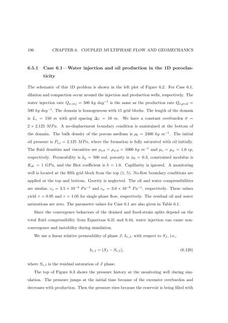
196 CHAPTER 6. COUPLED MULTIPHASE FLOW AND GEOMECHANICS<br />
6.5.1 Case 6.1—Water injection <strong>and</strong> oil production in the 1D poroelas-<br />
ticity<br />
The schematic of this 1D problem is shown in the left plot of Figure 6.2. For Case 6.1,<br />
dilation <strong>and</strong> compaction occur around the injection <strong>and</strong> production wells, respectively. The<br />
water injection rate Qw,inj = 500 kg day −1 is the same as the production rate Qo,prod =<br />
500 kg day −1 . The domain is homogeneous with 15 grid blocks. The length of the domain<br />
is Lz = 150 m with grid spacing ∆z = 10 m. We have a constant overburden ¯σ =<br />
2 × 2.125 MPa. A no-displacement boundary condition is maintained at the bottom of<br />
the domain. The bulk density of the porous medium is ρb = 2400 kg m −1 . The initial<br />
oil pressure is Po,i = 2.125 MPa, where the <strong>for</strong>mation is fully saturated with oil initially.<br />
The fluid densities <strong>and</strong> viscosities are ρo,0 = ρw,0 = 1000 kg m −1 <strong>and</strong> µo = µw = 1.0 cp,<br />
respectively. Permeability is kp = 500 md, porosity is φ0 = 0.3, constrained modulus is<br />
Kdr = 1 GPa, <strong>and</strong> the Biot coefficient is b = 1.0. Capillarity is ignored. A monitoring<br />
well is located at the fifth grid block from the top (1, 5). No-flow boundary conditions are<br />
applied at the top <strong>and</strong> bottom. Gravity is neglected. The oil <strong>and</strong> water compressibilities<br />
are similar, co = 3.5 × 10 −9 Pa −1 <strong>and</strong> cw = 3.0 × 10 −9 Pa −1 , respectively. These values<br />
yield τ = 0.95 <strong>and</strong> τ = 1.05 <strong>for</strong> single-phase flow, respectively. The residual oil <strong>and</strong> water<br />
saturations are zero. The parameter values <strong>for</strong> Case 6.1 are also given in Table 6.1.<br />
Since the convergence behaviors of the drained <strong>and</strong> fixed-strain splits depend on the<br />
total fluid compressibility from Equations 6.31 <strong>and</strong> 6.44, water injection can cause non-<br />
convergence <strong>and</strong> instability during simulation.<br />
We use a linear relative permeability of phase J, kr,J, with respect to SJ, i.e.,<br />
where Sr,J is the residual saturation of J phase.<br />
kr,J = (SJ − Sr,J), (6.120)<br />
The top of Figure 6.3 shows the pressure history at the monitoring well during sim-<br />
ulation. The pressure jumps at the initial time because of the excessive overburden <strong>and</strong><br />
decreases with production. Then the pressure rises because the reservoir is being filled with