Handout 1 - Clemson University
Handout 1 - Clemson University
Handout 1 - Clemson University
You also want an ePaper? Increase the reach of your titles
YUMPU automatically turns print PDFs into web optimized ePapers that Google loves.
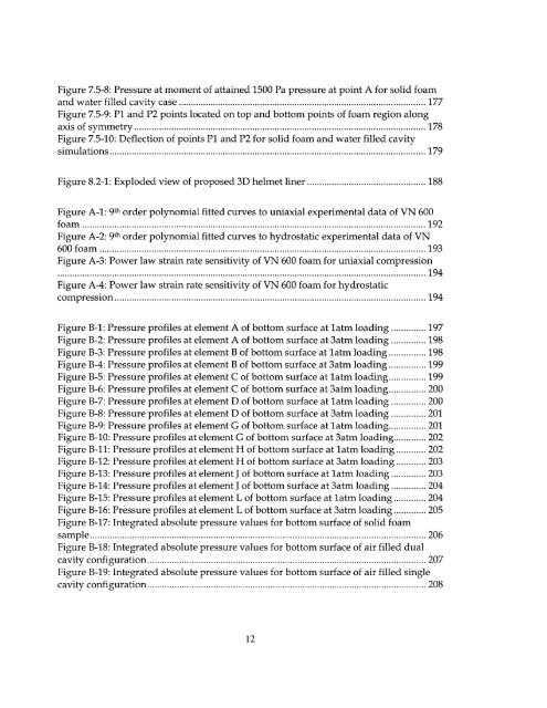
Figure 7.5-8: Pressure at moment of attained 1500 Pa pressure at point A for solid foam<br />
and w ater filled cavity case .................................................................................................... 177<br />
Figure 7.5-9: P1 and P2 points located on top and bottom points of foam region along<br />
axis sy of m m etry ...................................................................................................................... 178<br />
Figure 7.5-10: Deflection of points P1 and P2 for solid foam and water filled cavity<br />
sim u latio n s ................................................................................................................................ 1 79<br />
Figure 8.2-1: Exploded of proposed view 3D helmet liner ................................................ 188<br />
Figure A-1: 9th order polynomial fitted curves to uniaxial experimental data of VN 600<br />
fo am ...........................................................................................................................................<br />
Figure A-2: 9th order polynomial fitted curves to hydrostatic experimental data of VN<br />
1 9 2<br />
600 fo am .................................................................................................................................... 193<br />
Figure A-3: Power law strain rate sensitivity of VN 600 foam for uniaxial compression<br />
.....................................................................................................................................................<br />
Figure A-4: Power law strain rate sensitivity of VN 600 foam for hydrostatic<br />
1 9 4<br />
co m p ression .............................................................................................................................. 194<br />
Figure B-1: Pressure profiles at element A of bottom surface latm at loading .............. 197<br />
Figure B-2: Pressure profiles at element A of bottom surface 3atm at loading ....... 198<br />
Figure B-3: Pressure profiles element at B of bottom surface latm at loading ............... 198<br />
Figure B-4: Pressure profiles at element B of bottom surface 3atm at loading ............... 199<br />
Figure B-5: Pressure profiles at C element of bottom surface at latm loading.......199<br />
Figure B-6: Pressure profiles at element C of bottom surface at 3atm loading....... 200<br />
Figure B-7: Pressure profiles at element D of bottom surface at latm loading ....... 200<br />
Figure B-8: Pressure profiles at D element of bottom surface at 3atm loading ....... 201<br />
Figure B-9: Pressure profiles at element G of bottom surface at latm loading............... 201<br />
Figure B-10: Pressure profiles at element G of bottom surface at 3atm loading...... 202<br />
Figure B-11: Pressure profiles at element H of bottom surface latm at loading ...... 202<br />
Figure B-12: Pressure profiles at element H of bottom surface at 3atm loading ......<br />
Figure B-13: Pressure profiles at element J of bottom surface latm at loading .......<br />
Figure B-14: Pressure profiles at element J of bottom surface 3atm at loading .......<br />
203<br />
203<br />
204<br />
Figure B-15: Pressure profiles at element L of bottom surface latm at loading ...... 204<br />
Figure B-16: Pressure profiles at element L of bottom surface 3atm at loading ...... 205<br />
Figure B-17: Integrated absolute pressure values for bottom surface of solid foam<br />
sa m p le ........................................................................................................................................ 2 0 6<br />
Figure B-18: Integrated absolute pressure values for bottom surface of air filled dual<br />
cavity con figu ration ................................................................................................................. 207<br />
Figure B-19: Integrated absolute pressure values for bottom surface of air filled single<br />
cav ity con figu ration ................................................................................................................. 208


