A comparative discrete-dislocation/nonlocal crystal-plasticity
A comparative discrete-dislocation/nonlocal crystal-plasticity
A comparative discrete-dislocation/nonlocal crystal-plasticity
Create successful ePaper yourself
Turn your PDF publications into a flip-book with our unique Google optimized e-Paper software.
typeset2:/sco3/jobs1/ELSEVIER/msa/week.17/Pmsa15088y.001 Wed May 16 07:53:37 2001 Page Wed<br />
6<br />
D. Columbus, M. Grujicic / Materials Science and Engineering A000 (2001) 000–000<br />
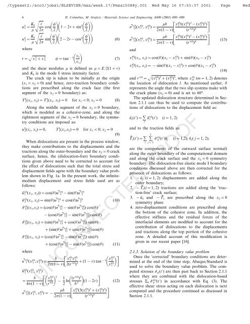
K I I<br />
r<br />
u 1= 2 cos1−2+sin2<br />
2<br />
2<br />
K I I<br />
r<br />
u 2= 2 sin2−2−cos2<br />
(6)<br />
2<br />
2<br />
where<br />
2 2 r=x 1+x2 =tan−1x2 (7)<br />
x1 and the shear modulus is defined as =E/2(1+)<br />
and KI is the mode I stress intensity factor.<br />
The crack tip is taken to be initially at the origin<br />
(x1=x 2=0) and hence, zero-traction boundary conditions<br />
are prescribed along the crack face (the first<br />
segment of the x2=0 boundary) as:<br />
I I T 1(x1, x2)=T 2(x1, x2)=0 for x10; x2=0 (8)<br />
Along the middle segment of the x2=0 boundary,<br />
which is modeled as a cohesive-zone, and along the<br />
rightmost segment of the x2=0 boundary, the symmetry<br />
conditions are imposed as:<br />
I u 2(x1, x2)=0, I T 1(x1,x2)=0 for x10; x2=0 (9)<br />
When <strong>dislocation</strong>s are present in the process window,<br />
they make contributions to the displacements and the<br />
tractions along the outer-boundary and the x2=0 crack<br />
surface, hence, the (<strong>dislocation</strong>-free) boundary conditions<br />
given above need to be corrected to account for<br />
the effect of <strong>dislocation</strong>s such that the total stress and<br />
displacement fields agree with the boundary value problem<br />
shown in Fig. 1a. In the present work, the infinitemedium<br />
displacement and stress fields used are as<br />
follows:<br />
(l) (l) (l)<br />
ũ 1 (x1, x2))=cos()u 1 −sin()u 2<br />
(l) (l) (l) ũ 2 (x1, x2)=sin()u 1 +cos()u 2 (10)<br />
(l) (l) (l) ˜ 11(x1,x2)=(cos()<br />
11−sin()<br />
12)<br />
cos()<br />
(l) (l) −(cos() 12−sin()<br />
22)<br />
sin()<br />
(l) (l) (l) ˜ 22(x1,<br />
x2)=(sin() 11+cos()<br />
12)<br />
sin()<br />
(l) (l) +(sin() 12+cos()<br />
22)cos()<br />
(l) (l) (l) ˜ 12(x1,<br />
x2)=(cos() 11−sin()<br />
12)<br />
sin()<br />
(l) (l) +(cos() 12−sin()<br />
22)cos()<br />
(11)<br />
where<br />
(l) (l)<br />
b<br />
(l) (l) (l) x1 x2<br />
u 1 (x1 ,x2 )=<br />
2(1−) 2(r (l) ) 2+(1−) tan−1x(l) 2<br />
x(l)n 1<br />
(l) (l) (l) ũ2 (x1 , x2 )<br />
=<br />
b<br />
(l)<br />
x2 4(1−) r (l)2<br />
− 1<br />
2 ln(r(l) ) 2<br />
b 2 n (1−2) (12)<br />
(l) (l) 2 (l) 2 b<br />
(l) (l) (l) x2 (3(x1 ) +(x2 ) )<br />
11(x1<br />
, x2 )=−<br />
2(1−) (r (l) ) 4<br />
(l) (l) 2 (l) 2 b<br />
(l) (l) (l) x2 ((x1 ) −(x2 ) )<br />
22(x1<br />
, x2 )=<br />
2(1−) (r<br />
n<br />
(l) ) 4 n<br />
(l) (l) 2 (l) 2 b<br />
(l) (l) (l) x1 ((x1 ) −(x2 ) )<br />
12(x1<br />
, x2 )=<br />
2(1−) (r (l) ) 4 n (13)<br />
and<br />
(l) (l) (l) x1 (x1, x2)=cos()(x1−x 1 )+sin()(x2−x 2 )<br />
(l) (l) (l) x2 (x1, x2)=−sin()(x1−x 1 )+cos()(x2−x 2 )<br />
(14)<br />
and r (l) (l) 2 (l) 2 (l)<br />
=(x1 ) +(x2 ) , where x m (m=1, 2) denotes<br />
the location of <strong>dislocation</strong> l. As mentioned earlier, <br />
represents the angle that the two slip systems make with<br />
the crack plane (x2=0) and is set to 60°.<br />
The updated <strong>dislocation</strong> structure determined in Section<br />
2.1.1 can thus be used to compute the contributions<br />
of <strong>dislocation</strong>s to the displacement field as:<br />
(l) ũi(t)= ũ i (t)<br />
l<br />
(i=1, 2)<br />
and to the traction fields as:<br />
2<br />
(l) T i(t)= ˜ ij (t)hj<br />
l j=1<br />
(i=1,2); hj( j=1, 2);<br />
are the components of the outward surface normal)<br />
along the outer boundary of the computational domain<br />
and along the crack surface and the x2=0 symmetry<br />
boundary. The <strong>dislocation</strong>-free elastic mode I boundary<br />
conditions discussed above are then corrected for the<br />
presence of <strong>dislocation</strong>s as follows:<br />
1. −ũi (i=1, 2) displacements are added along the<br />
outer boundary;<br />
2. −T i(i=1, 2) tractions are added along the ‘traction-free’<br />
crack surface;<br />
3. −ũ2 and −T 1 are prescribed along the x2=0 symmetry plane<br />
4. zero-displacement conditions are prescribed along<br />
the bottom of the cohesive zone. In addition, the<br />
effective stiffness and the residual forces of the<br />
interfacial elements are modified to account for the<br />
contribution of <strong>dislocation</strong>s to the displacements<br />
and tractions along the top portion of the cohesive<br />
zone. A detailed account of this modification is<br />
given in our recent paper [16].<br />
2.1.3. Solution of the boundary alue problem<br />
Once the ‘corrected’ boundary conditions are determined<br />
at the end of the time step, Abaqus/Standard is<br />
used to solve the boundary value problem. The computed<br />
stresses ˆ ij(t) are then past back to Section 2.1.1<br />
where they are combined with the <strong>dislocation</strong>-based<br />
(k) stresses k ˜ ij (t) in accordance with Eq. (3). The<br />
effective shear stress acting on each <strong>dislocation</strong> is next<br />
computed and the procedure continued as discussed in<br />
Section 2.1.1.<br />
UNCORRECTED PROOF


