Download - Coordinates
Download - Coordinates
Download - Coordinates

You also want an ePaper? Increase the reach of your titles
YUMPU automatically turns print PDFs into web optimized ePapers that Google loves.
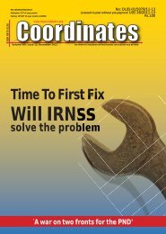
Fig. 2 Experimental GNSS receiver RF channel<br />
loss, and selectivity are basically<br />
available for GPS L1 frequency.<br />
Some manufactures offer a few<br />
filters for GPS L2 frequency too.<br />
The RF filters for other GNSS<br />
signals like GPS L5, GLONASS<br />
and Galileo E5, E5a, E5b, E6 are<br />
basically not available at present.<br />
The development and manufacture<br />
of custom-made RF filters are<br />
generally out of feasibility of the<br />
researcher. The solution of this<br />
problem is an implementation of<br />
helical filters, which are suitable<br />
for prototyping. Helical filters are<br />
customer tunable and available<br />
in sufficient range from various<br />
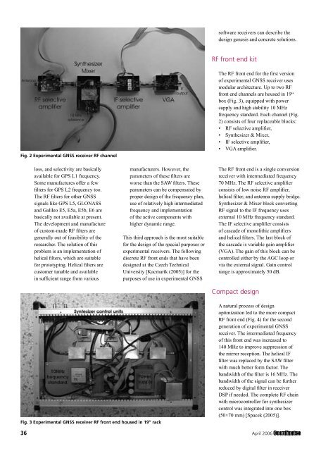
Fig. 3 Experimental GNSS receiver RF front end housed in 19” rack<br />
manufacturers. However, the<br />
parameters of these filters are<br />
worse than the SAW filters. These<br />
parameters can be compensated by<br />
proper design of the frequency plan,<br />
use of relatively high intermediated<br />
frequency and implementation<br />
of the active components with<br />
higher dynamic range.<br />
This third approach is the most suitable<br />
for the design of the special purposes or<br />
experimental receivers. The following<br />
discrete RF front ends that have been<br />
designed at the Czech Technical<br />
University [Kacmarik (2005)] for the<br />
purposes of use in experimental GNSS<br />
software receivers can describe the<br />
design genesis and concrete solutions.<br />
RF front end kit<br />
The RF front end for the first version<br />
of experimental GNSS receiver uses<br />
modular architecture. Up to two RF<br />
front end channels are housed in 19“<br />
box (Fig. 3), equipped with power<br />
supply and high stability 10 MHz<br />
frequency standard. Each channel (Fig.<br />
2) consists of four replaceable blocks:<br />
• RF selective amplifier,<br />
• Synthesizer & Mixer,<br />
• IF selective amplifier,<br />
• VGA amplifier.<br />
The RF front end is a single conversion<br />
receiver with intermediated frequency<br />
70 MHz. The RF selective amplifier<br />
consists of low noise RF amplifier,<br />
helical filter, and antenna supply bridge.<br />
Synthesizer & Mixer block converting<br />
RF signal to the IF frequency uses<br />
external 10 MHz frequency standard.<br />
The IF selective amplifier consists<br />
of cascade of monolithic amplifiers<br />
and helical filters. The last block of<br />
the cascade is variable gain amplifier<br />
(VGA). The gain of this block can be<br />
controlled either by the AGC loop or<br />
via the external signal. Gain control<br />
range is approximately 50 dB.<br />
Compact design<br />
A natural process of design<br />
optimization led to the more compact<br />
RF front end (Fig. 4) for the second<br />
generation of experimental GNSS<br />
receiver. The intermediated frequency<br />
of this front end was increased to<br />
140 MHz to improve suppression of<br />
the mirror reception. The helical IF<br />
filter was replaced by the SAW filter<br />
with much better form factor. The<br />
bandwidth of the filter is 16 MHz. The<br />
bandwidth of the signal can be further<br />
reduced by digital filter in receiver<br />
DSP if needed. The complete RF chain<br />
with microcontroller for synthesizer<br />
control was integrated into one box<br />
(50×70 mm) [Spacek (2005)].<br />
36 April 2006