232M100 I/O Module
232M100 I/O Module
232M100 I/O Module

Create successful ePaper yourself
Turn your PDF publications into a flip-book with our unique Google optimized e-Paper software.
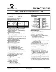
Integrity Instruments <strong>232M100</strong> Series User Manual<br />
Integrity<br />
Instruments<br />
P.O. Box 451 Order Phone 800-450-2001<br />
Pine River Minnesota Fax Phone 218-587-3414<br />
56474 USA Tech Phone 218-587-3120<br />
http://www.integrityusa.com<br />
<strong>232M100</strong> Series<br />
I/O <strong>Module</strong>s<br />
Digital I/O<br />
Analog I/O<br />
1
2<br />
Integrity Instruments <strong>232M100</strong> Series User Manual<br />
Table of Contents<br />
Introduction<br />
Features .........................................................................................3<br />
Quick Start ....................................................................................4<br />
Communications<br />
RS-232 Packet Information ...........................................................6<br />
Commands and Responses<br />
Command and Response Table ....................................................7<br />
Command and Response Examples ............................................8<br />
Analog Control Nibble ....................................................................9<br />
<strong>Module</strong> Configuration<br />
EEPROM Map .............................................................................10<br />
EEPROM Map .............................................................................11<br />
Sampling rates<br />
Analog and digital ........................................................................12<br />
Modes of Operation<br />
Polled Mode .................................................................................12<br />
Asynchronous Update Mode .......................................................12<br />
Continuous stream Mode .............................................................13<br />
Continuous stream Mode Configuration EEPROM Map ..............14<br />
Continuous stream Mode Example ..............................................15<br />
Digital I/O Technical Information<br />
Digital I/O Characteristics ............................................................16<br />
Digital I/O Port Configuration Example ........................................16<br />
PWM Characteristics ...................................................................17<br />
PWM Commands .........................................................................17<br />
Analog I/O Technical Information<br />
Analog I/O Characteristics ...........................................................18<br />
Voltage References .....................................................................18<br />
Analog Voltage Sampling ............................................................18<br />
Analog Conversion ......................................................................19<br />
Analog Offset Calibration .............................................................19<br />
Analog Current Sampling ............................................................20<br />
Analog Current Conversion .........................................................20<br />
Digital & Analog I/O Port Specifications<br />
Digital & Analog pin outs ..............................................................21<br />
<strong>Module</strong> Specifications<br />
PCB Illustrations ..........................................................................22<br />
Dip switch and jumper settings ....................................................22<br />
232M300 Series <strong>Module</strong> Specifications .......................................23<br />
232 cabling and specifications .....................................................23<br />
Peripherals<br />
Analog Connection Board ...........................................................24<br />
Signal Conditioner Board ............................................................24<br />
DB15/DB25 Terminal Strip Board ...............................................24<br />
Digital Interface Board ................................................................24
Integrity Instruments <strong>232M100</strong> Series User Manual<br />
Introduction<br />
Welcome to the Integrity Instruments <strong>232M100</strong> Series of I/O modules. These modules<br />
using RS-232 communications are available in an enclosure, or open allowing you the<br />
end user complete flexibility when determining the parameters for your project.<br />
Configurations for <strong>232M100</strong> series model are:<br />
232M1A0CE 8 digital I/O and 8 channels A/D conversion<br />
With enclosure<br />
232M1A0CT 8 digital I/O and 8 channels A/D conversion<br />
No enclosure<br />
I/O <strong>Module</strong> features:<br />
MPU: Microchip PIC18F4455<br />
MPU Clock: 32 Mhz<br />
Interface: RS-232 (single ended)<br />
Baud: 9600, 19200, 57600, 115200 (DIP switch selectable)<br />
LED: Bicolor diagnostic LED<br />
Watchdog: MPU has built-in watchdog timer<br />
POR: MPU contains timed Power On Reset circuitry<br />
Brownout: MPU brownout detection ciruictry built-in<br />
Temperature: 0° to 70°C (32° to 158°F) Commercial Temperature Range<br />
PCB: FR4<br />
Power: 7.5Vdc to 15.0 Vdc (approx. 50 ma nominal current)<br />
24 Vdc maximum 100 ma current draw.<br />
<strong>232M100</strong><br />
10 bit analog<br />
acquisition<br />
digital I/O lines<br />
RS-232<br />
Full duplex<br />
50’ max.<br />
<strong>232M100</strong> Series Features<br />
• 8 Digital I/O lines<br />
• 8 10 bit Analog Inputs<br />
• PWM Output<br />
• 32 bit Pulse Counter 1 Mhz<br />
3
4<br />
Integrity Instruments <strong>232M100</strong> Series User Manual<br />
Quick Start Instructions<br />
You need the following:<br />
• EZTerminal program available free on our website http://www.integrityusa.com<br />
• An open COMPORT on your PC<br />
• Power supply PS9J (9VDC 400 ma unregulated)<br />
• A cable to connect your PC (C9F9M-6 6 foot serial cable)<br />
Make these DIP switch settings for 115,200 baud<br />
SW1: ON<br />
SW2: ON (These are factory default settings, see page 21)<br />
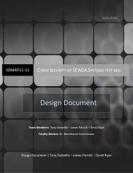
Launch the EZTerminal program<br />
1. Double click the icon in whatever area you have put the program.<br />
2. Under “Settings” then choose Comport and select your RS-232 port, 115,200 Baud<br />
Rate, 8 Data Bits, NO PARITY, and 1 Stop Bits.<br />
3. Under “Settings” now choose “Terminal Settings”, and check the “Append LF to<br />
incoming CR” box, and “Local echo typed characters” check box.<br />
4. You may change the color of the transmitted and received characters by going under<br />
“Settings” and selecting “Colors” then “Transmit” or “Receive” and pick the color of<br />
your choice.<br />
Step 1<br />
Steps 2 & 3
Integrity Instruments <strong>232M100</strong> Series User Manual<br />
Step 2<br />
Your First Command<br />
Now that you have a EZTerminal session running, your ready to power up the <strong>232M100</strong><br />
Series I/O <strong>Module</strong>. After powering up your <strong>232M100</strong> Series <strong>Module</strong>, EZTerminal will<br />
receive a welcome message from the unit indicating you are ready to provide your first<br />
command.<br />
RS-232 Firmware Version 3.1 Command:<br />
• Typethe letter V and the Enter Key<br />
• You should see V30 on the screen<br />
• NOTE: Make sure to type CAPITAL V, not lowercase v!<br />
Step 3<br />
Step 4 Step 4<br />
After your first command, see Commands and Responses section for more commands.<br />
Screenshots and setup instructions performed running EZTerminal on a PC installed with<br />
Microsoft® Windows® XP Operating System.<br />
5
6<br />
Integrity Instruments <strong>232M100</strong> Series User Manual<br />
Communications<br />
The Integrity Instruments <strong>232M100</strong> Series I/O <strong>Module</strong>s support RS-232 communications<br />
interface using simple ASCII commands. A carriage return (decimal code 13 or Hex<br />
code 0x0D) marks the end of each command. Line feeds (decimal code 10 or Hex code<br />
0x0A) are ignored.<br />
RS-232 Interface:<br />
• RS-232 operates Full Duplex<br />
• RS-232 modules can also enter Continuous Stream Mode whereby the module is<br />
configured via EEPROM settings to continuously send data to output its current<br />
Digital, Counter or Analog readings.<br />
RS-232 Command Format<br />
RS-232 Command Format<br />
Command/Response<br />
ASCII<br />
CR<br />
carriage return<br />
13 (0x0D hex)<br />
NOTE<br />
• All numeric data is represent as ASCII Hexadecimal integers (values x/y in the<br />
Command and Response table)<br />
• If a module receives an illegal or improperly formatted command, Error Response is<br />
sent.<br />
• All ASCII characters are CASE SENSITIVE (use all capital letters!)
Integrity Instruments <strong>232M100</strong> Series User Manual<br />
Commands and Responses v3.0 Firmware<br />
Command<br />
Sent by Host<br />
Response<br />
Sent by I/O <strong>Module</strong><br />
V Vxy Firmware version x.y<br />
Description<br />
I Ixxyy Input digital port status<br />
xx = 00<br />
yy = PORT2<br />
Also returns current output port status<br />
Oxxyy O Output digital port:<br />
xx = (ignored)<br />
yy = PORT2)<br />
Txxyy T Set digital direction:<br />
xx = (ignored)<br />
yy = PORT2<br />
bit set(1) = Input, bit clear(0) = Output<br />
G Gxxyy Get current digital direction:<br />
xx = 00<br />
yy = PORT2<br />
bit set(1) = Input, bit clear(0) = Output<br />
N Nxxxxxxxx Get Pulse Counter<br />
(xxxxxxxx 32 bit counter value)<br />
M M Clear Pulse Counter<br />
Uy Uyxxx Unipolar sample analog (y control niblle,<br />
xxx analog value)<br />
Lyxxx L D/A output (y channel setting 0 or 1,<br />
xxx 12 bit D/A output)<br />
K Kxx Get receive error count (xx current count)<br />
J J Clear receive error count<br />
Pxxyyy P PWM (xx = PWM frequency, yyy = PWM duty)<br />
Wyyxx W Write EEPROM (yy address, xx value)<br />
Ryy Rxx Read EEPROM (yy address in command, xx<br />
value in reponse)<br />
S S Start continuous stream mode<br />
H H Halt continuous stream mode<br />
Z Z Reset CPU<br />
X Command error response sent by module<br />
7
8<br />
Integrity Instruments <strong>232M100</strong> Series User Manual<br />
Commands and Responses<br />
The following table illustrates actual command and response data for an RS-232<br />
interface.<br />
NOTE:<br />
• All numeric data is represent as ASCII Hexadecimal integers.<br />
• The symbol ↵ equates to a carriage return (decimal 13, hex 0x0D).<br />
Command<br />
Sent by Host<br />
Response<br />
Sent by I/O<br />
Description<br />
V↵ V40↵ <strong>Module</strong> Firmware version 3.0<br />
I↵ I000F↵ Input digital port [PORT2 bits 0-3 ON]<br />
[PORT2 bits 4-7 OFF]<br />
Note: this command also returns the current<br />
digital output<br />
O007F↵ O↵ Output digital port<br />
[PORT2 bit 7 OFF, bits 0-6 ON]<br />
T0080↵ T↵ Set digital direction<br />
[PORT2 bit 7 INPUT, bits 0-6 OUTPUT]<br />
G↵ G0080↵ Get current digital direction<br />
[PORT2 bit 7 INPUT, bits 0-6 OUTPUT]<br />
N↵ N0000000F↵ Get pulse counter: Current count = 15<br />
M↵ M↵ Clear pusle counter: Current count = 0<br />
U3↵ U340F↵ Unipolar analog control nibble = 0x3<br />
Analog reading = 0x40F<br />
K↵ K00↵ Current receive errors = 0<br />
J↵ J↵ Clear receive error count: Current receive errors<br />
P4801F↵ P↵ PWM freq = 50499 Hz, PWM duty = 10.6%<br />
W0410↵ W↵ Write EEPROM Address 0x04 with value 0x10<br />
R04↵ R10↵ Read EEPROM Adress 0x04 (value is 0x10)<br />
S↵ S↵<br />
I00FF↵<br />
U800F↵<br />
I00FF↵<br />
U800F↵<br />
START continuous stream mode<br />
See Modes of Operation section<br />
This example illustrates continuous stream mode<br />
configured to continuously update with Input<br />
Digital Port command and Query Analog<br />
command with control 0x1. The module<br />
continues until a command H↵is received.<br />
H↵ H↵ HALT continuous stream mode<br />
Z↵ Z↵ Reset CPU (forces a watchdog timeout)
Integrity Instruments <strong>232M100</strong> Series User Manual<br />
Analog Control Nibble and Example<br />
The <strong>232M100</strong> Series I/O modules equipped with analog inputs utilizes the internal<br />
analog to digital conversion in the processor chip. In the process of performing a data<br />
sample, the user sends a control nibble to the <strong>232M100</strong> Series module. The <strong>232M100</strong><br />
Series module in turn performs a data conversion using the control nibble and transmitts<br />
a response data sample back. The following table lists each of the 8 possible analog<br />
configurations.<br />
NOTE<br />
• All numeric data is represent as ASCII Hexadecimal integers<br />
• The symbol ↵ equates to a carriage return (decimal 13, hex 0x0D)<br />
• See Analog I/O Technical Information section for sample to volts conversion<br />
Control Nibble Analog Sample<br />
0 Single Point: CH0<br />
1 Single Point: CH1<br />
2 Single Point: CH2<br />
3 Single Point: CH3<br />
4 Single Point: CH4<br />
5 Single Point: CH5<br />
6 Single Point: CH6<br />
7 Single Point: CH7<br />
Command<br />
Sent by Host<br />
Response<br />
Sent by I/O <strong>Module</strong><br />
Description<br />
U2↵ U2123↵ Unipolar sample CH2 (Control = 2 )<br />
Analog sample = 0x123 (decimal 291)<br />
U6↵ U6123↵ Unipolar sample CH6 (Control = 2 )<br />
Analog sample = 0x123 (decimal 291)<br />
9
10<br />
Integrity Instruments <strong>232M100</strong> Series User Manual<br />
EEPROM Map:<br />
Address Description<br />
0x00 N/A - Reserved<br />
0x01 N/A - Reserved<br />
0x02 N/A - Reserved<br />
0x03 Data Direction Port 2<br />
Bit set (1) = Input Bit clear (0) = Output<br />
[factory default = 0xFF]<br />
0x04/0x05 Asynchronous Update Mode Configuration<br />
0x0000= No asynchronous updates<br />
0x0001= Change Update on Digital Input or Counter change<br />
0x0002...0xFFFF = Timed Update (Time = Value * 1 milliseconds)<br />
16 bits - upper byte in 0x04 lower byte in 0x05<br />
[factory default = 0x0000]<br />
0x06 N/A - Reserved<br />
0x07 Port 2 Power on Default output<br />
[factory default = 0x00]<br />
0x08<br />
See Note 1<br />
0x09 to 0x0E N/A - Reserved<br />
Expander board flag (Opto-22 ® modules attached)<br />
0x00 = No expander board attached<br />
0xFF = Expander board attached (invert digital signals)<br />
[factory default = 0x00]<br />
WARNING!<br />
The I/O <strong>Module</strong> CPU must be reset before new EEPROM settings take effect.<br />
NOTE:<br />
1. This flag is used when an expander board is attached. It allows for polarity interface<br />
to the industry standard I/O modules used with the expander board based on open<br />
collector logic that these modules use.<br />
2. This is used to slow the A/D Channel sample clock rate. This may help when the A/D<br />
channels have a high impedance input attached.
Integrity Instruments <strong>232M100</strong> Series User Manual<br />
EEPROM Map:<br />
Address Description<br />
0x0F N/A - Reserved<br />
0x10 Continuous Stream Analog configuration count<br />
0x00 = No analog stream readings<br />
0x01... 0x08 = Number of analog queries<br />
[factory default = 0x00]<br />
See Modes of Operation Continuous Stream for locations<br />
0x11...0x1A<br />
0x11 Analog Query 1 - control byte - analog control nibble<br />
0x12 Analog Query 2 - control byte - analog control nibble<br />
0x13 Analog Query 3 - control byte - analog control nibble<br />
0x14 Analog Query 4 - control byte - analog control nibble<br />
0x15 Analog Query 5 - control byte - analog control nibble<br />
0x16 Analog Query 6 - control byte - analog control nibble<br />
0x17 Analog Query 7 - control byte - analog control nibble<br />
0x18 Analog Query 8 - control byte - analog control nibble<br />
0x19 Continuous Stream Digital Input configuration<br />
0x00 = Digital Input status OFF<br />
0xFF= Digital Input status ON<br />
[factory default = 0x00]<br />
0x1A Continuous Stream Pulse Counter configuration<br />
0x00 = Pulse Counter status OFF<br />
0xFF = Pulse Counter status ON<br />
[factory default = 0x00]<br />
0x1B to 0x3A N/A - Reserved calibration DO NOT TOUCH<br />
0x3B to 0xFF Available to User<br />
11
12<br />
Integrity Instruments <strong>232M100</strong> Series User Manual<br />
Analog& Digital I/O Sampling Rates<br />
Sampling rates are in samples per second for a single analog channel or 8 bit digital I/O<br />
port tested on Windows 2000 850 Mhz P3 with A/D clock running at full speed. Samples<br />
per channel = Sample rate ÷ number of channels being sampled.<br />
Modes of Operation:<br />
The Integrity Instruments I/O modules can operate in three operation modes:<br />
1) Polled<br />
2) Asynchronous Update<br />
3) Continuous Stream.<br />
These modes of operation can be used singularly or together in combination.<br />
#1) Polled Mode<br />
By far, the Polled Mode is the most common usage of the <strong>232M100</strong> Series I/O modules.<br />
In this mode the Host computer sends a command to the I/O <strong>Module</strong>s which in turn sends<br />
an associated response back to the Host computer.<br />
HOST<br />
Computer<br />
Analog I/O<br />
Baud Rate Polled Mode Continuous Mode<br />
115,200 777 1515<br />
57,600 412 847<br />
19,200 143 310<br />
9600 72 157<br />
Digital I/O<br />
Baud Rate Polled Mode Continuous Mode<br />
115,200 878 1884<br />
57,600 456 960<br />
19,200 156 319<br />
9600 78 159<br />
1 - Command Sent by Host<br />
2 - Response Sent by <strong>Module</strong><br />
I/O <strong>Module</strong><br />
<strong>232M100</strong><br />
Series<br />
#2) Asynchronous Update Mode<br />
The I/O <strong>Module</strong> sends data without the Host sending a command to poll the I/O <strong>Module</strong><br />
in Asynchronous Update Mode.<br />
NOTE: Asynchronous Update Mode is configured using EEPROM locations 0x04/0x05.
Integrity Instruments <strong>232M100</strong> Series User Manual<br />
Value at EEPROM Location 0x04/0x05 Description<br />
0x0000 Asynchronous Update Mode disabled<br />
0x0001 State Change Update<br />
Digital Input or Pulse Counter change<br />
0x0002 to 0xFFFF<br />
Decimal Range<br />
2 to 65535)<br />
#2a) Asynchronous Update Mode — State Change Update<br />
When EEPROM locations 0x04/0x05 = 0x01, the <strong>232M100</strong> Series I/O module enters an<br />
asynchronous update mode whereby any detected change on the Digital Input port or the<br />
Counter Capture port causes the I/O module to transmit data to the host.<br />
Status Change Data Sent by I/O <strong>Module</strong><br />
Digital Input port change Ixxxx<br />
Counter Capture change Nxxxx<br />
HOST<br />
Computer<br />
Timed Update<br />
Time = Value * 1 millisecond<br />
Range = .002 second - 65.5 seconds<br />
1 - Data Sent by <strong>Module</strong><br />
#2b) Asynchronous Update Mode — Timed Update<br />
When EEPROM locations 0x04/0x05 = 0x0002...0xFFFF, the <strong>232M100</strong> Series I/O<br />
module enters a timed update mode whereby the I/O module will send data to the host<br />
after the specified time period has elapsed.<br />
Time Period = Value (EEPROM locations 0x04/0x05) * .001 second<br />
I/O <strong>Module</strong><br />
<strong>232M100</strong><br />
When using Asynchronous Update Mode, the I/O module uses the Continuous Stream<br />
Mode configuration to determine the data sent to the host.<br />
#3) Continuous Stream Mode<br />
The final mode of operation is Continuous Stream mode. This mode constantly sends or<br />
streams data to the host until the host halts the mode. In brief, the I/O <strong>Module</strong> can send 0<br />
thru 8 analog samples, digital input status, and the counter capture status.<br />
The I/O module uses parameters found in EEPROM locations 0x10 thru 0x1A to<br />
configure the Continuous Stream mode. Therefore, the EEPROM must be configured<br />
before engaging the Continuous Stream mode.<br />
Continuous Stream Mode setup steps<br />
1. Configure EEPROM locations 0x10 thru 0x1A<br />
2. Begin Continuous Stream mode by sending command ‘S’ to the I/O <strong>Module</strong><br />
3. Halt Continuous Stream mode by sending command ‘H’ to the I/O <strong>Module</strong><br />
13
14<br />
Integrity Instruments <strong>232M100</strong> Series User Manual<br />
Continuous Stream Mode Configuration — EEPROM Locations<br />
All parameters configuring the Continuous Stream mode are strored in EEPROM. See the<br />
following table for a description of the locations and the parameters. Use command ‘W’ to<br />
update EEPROM values.<br />
EEPROM Value Description<br />
0x10 0x00...0x08 Analog Configuration<br />
0x00 = No analog samples<br />
0x01...0x08 = Number of analog samples<br />
0x11<br />
Sample 1<br />
0x12<br />
Sample 2<br />
0x13<br />
Sample 3<br />
0x14<br />
Sample 4<br />
0x15<br />
Sample 5<br />
0x16<br />
Sample 6<br />
0x17<br />
Sample 7<br />
0x18<br />
Sample 8<br />
0x19 0x00<br />
0xFF<br />
0x1A 0x00<br />
0xFF<br />
Continuous Stream Mode Example<br />
0x8y ... 0x8y Unipolar Analog: y = analog control nibble<br />
0x8y ... 0x8y Unipolar Analog: y = analog control nibble<br />
0x8y ... 0x8y Unipolar Analog: y = analog control nibble<br />
0x8y ... 0x8y Unipolar Analog: y = analog control nibble<br />
0x8y ... 0x8y Unipolar Analog: y = analog control nibble<br />
0x8y ... 0x8y Unipolar Analog: y = analog control nibble<br />
0x8y ... 0x8y Unipolar Analog: y = analog control nibble<br />
0x8y ... 0x8y Unipolar Analog: y = analog control nibble<br />
Digital Input status disabled<br />
Digital Input status enabled<br />
Pulse Counter status disabled<br />
Pulse Counter status enabled<br />
In this example, the I/O module EEPROM is configured to take 3 Analog samples and<br />
update the Counter status.<br />
EEPROM Location 0x10 0x03 Take 2 Analog samples<br />
EEPROM Location 0x11 0x82 Sample 1 - Unipolar sample CH2<br />
EEPROM Location 0x12 0x85 Sample 2 - Unipolar sample CH5<br />
EEPROM Location 0x13 0x87 Sample 3 - Unipolar sample CH7<br />
EEPROM Location 0x1A 0x01 Pulse Counter Status enabled
Integrity Instruments <strong>232M100</strong> Series User Manual<br />
Continuous Stream Mode Example continued<br />
The following table illustrates the Host Command and I/O <strong>Module</strong> responses for the continuous<br />
stream example configuration and usage.<br />
EEPROM Location 0x10 0x03 Take 2 Analog samples<br />
EEPROM Location 0x11 0x82 Sample 1 - Unipolar sample CH2<br />
EEPROM Location 0x12 0x85 Sample 2 - Unipolar sample CH5<br />
EEPROM Location 0x13 0x87 Sample 3 - Unipolar sample CH7<br />
EEPROM Location 0x1A 0x01 Pulse Counter Status enabled<br />
NOTE<br />
• All numeric data is represent as ASCII Hexadecimal integers<br />
• The symbol ↵ equates to a carriage return (decimal 13, hex 0x0D)<br />
Host Sends I/O <strong>Module</strong> Sends<br />
W1003↵ W↵<br />
W1182↵ W↵<br />
W1285↵ W↵<br />
W1287↵ W↵<br />
W1A01↵ W↵<br />
S↵<br />
S↵ Continuous Stream mode started<br />
U2023↵<br />
U5823↵<br />
U5823↵<br />
N0000 0044↵<br />
U2023↵<br />
U5823↵<br />
U5823↵<br />
N0000 0044↵<br />
.... repeats continually<br />
H↵ H↵ Continuous Stream mode halted<br />
The HOST may send any command during the Continuous Stream mode and it will be<br />
accepted and processed by the I/O <strong>Module</strong> as in normal operation.<br />
NOTE<br />
Engaging the Continuous Stream mode at a high baud rate (115.2K baud) may<br />
overwhelm certain host computer systems due to the high volume of data transmitted on<br />
the RS-232 link. The is especially true of slower 386 or 486 based systems running<br />
Windows 95 with limited memory resources.<br />
15
16<br />
Integrity Instruments <strong>232M100</strong> Series User Manual<br />
Digital I/O Characteristics<br />
The following chart lists the Digital I/O characteristics and values.<br />
Characteristic Value<br />
Digital I/O Current I/O line source & sink 25 ma<br />
Total current PORT2 200 ma<br />
Digital I/O Voltage Levels Input Off (0) = 0V - 0.8V<br />
Input On (1) = 2.0V - 5.0V<br />
Output Off (0) = 0.6V max.<br />
Output On (1) = 4.3V min.<br />
Pulse Counter Input 1 Mhz max. input rate<br />
32 bit counter capture<br />
Counter increments on high-low transition<br />
Digital Port Configuration Example<br />
Any Digital I/O configuration changes made to the I/O <strong>Module</strong> using the ‘T’ command<br />
are stored in EEPROM location 0x03.<br />
EEPROM Location 0x03 Port 2 I/O Configuration<br />
When using either the ‘T’ command or directly writing to EEPROM using the ‘W’<br />
command, a binary 1 at a bit location puts the I/O line into Input mode, while a binary 0 at<br />
a bit location puts the I/O line into Output mode.<br />
NOTE<br />
• All numeric data is represent as ASCII Hexadecimal integers<br />
• The symbol ↵ equates to a carriage return (decimal 13, hex 0x0D)<br />
Host Command <strong>Module</strong> Response Action<br />
T0000↵ T↵ All I/O lines are configured as Outputs<br />
T00FF↵ T↵ All I/O lines are configured as Inputs<br />
T000F↵ T↵ Port 2 bits 0-3 Inputs<br />
Port 2 bits 4-7 Outputs<br />
T00F0↵ T↵ Port 2 bits 0-3 Outputs<br />
Port 2 bits 4-7 inputs<br />
T0034↵ T↵ Port 2 bits 4,5,2 Inputs<br />
Port 2 bits 7,6,3,1,0 Outputs
Integrity Instruments <strong>232M100</strong> Series User Manual<br />
Pulse Width Modulation (PWM) Characteristics<br />
The <strong>232M100</strong> Series modules have a configurable PWM output. There are two settings<br />
to configure for proper PWM operation: PWM frequency and PWM duty cycle.<br />
PWM — Command<br />
Pxxyyy xx = Pwm_Divisor yyy = Pwm_Duty (10 bits max.)<br />
Pwm_Divisor = 0x00 ... 0xFF<br />
Pwm_Duty = 0x000 ... 0x3FF Pwm_Duty = 0, PWM output is disabled (output 0)<br />
PWM — Control Values (32 Mhz clock)<br />
PWM Period = (Pwm_Divisor + 1) / 8,000,000<br />
PWM Duty Period = (Pwm_Duty) / 32,000,000<br />
Duty_Resolution = log (32,000,000/ Fpwm) / log (2)<br />
PWM Duty Cycle % = PWM Duty Period / PWM Period<br />
if (PWM Duty Period > PWM Period) then PWM Duty Cycle = 100%<br />
Pwm_Divisor PWM Freq Duty_Resolution<br />
0xFF (255) 31,250 Hz 10 bits* (see note)<br />
0xFE (254) 31,373 Hz 10 bits<br />
0x5B (91) 86,957 Hz 8 bits<br />
0x00 (0) 8,000,000 Hz 2 bits<br />
* Note: Pwm_Divisor 0xFF cannot achieve complete 100% duty cycle. Use Pwm_Divisor<br />
0xFE if 100% duty cycle is required.<br />
Example PWM Commands<br />
• All numeric data is represent as ASCII Hexadecimal integers<br />
• The symbol ↵ equates to a carriage return (decimal 13, hex 0x0D)<br />
Host Command <strong>Module</strong> Response Action<br />
P0000↵ P↵ PWM off<br />
Any duty cycle of 0 disables PWM output<br />
P4801F↵ P↵ PWM frequency = 109,599 Hz<br />
PWM duty = 10.6%<br />
PFE3FF↵ P↵ PWM frequency = 31,327 Hz<br />
PWM duty = 100%<br />
PFE1FE↵ P↵ PWM frequency = 31,327 Hz<br />
PWM duty = 50%<br />
17
18<br />
Integrity Instruments <strong>232M100</strong> Series User Manual<br />
Analog I/O Characteristics:<br />
Characteristic Value<br />
A/D Converter 0 to 10 Volt input<br />
Linearity Error
Integrity Instruments <strong>232M100</strong> Series User Manual<br />
Voltage Conversion<br />
The Analog conversion value obtained from the <strong>232M100</strong> Series module is represented<br />
as an integer value unsigned for Unipolar sample and is normally converted to a Real or<br />
Floating Point number for ultimate usage.<br />
Vref = 5.000 standard<br />
Unipolar Voltage Conversion Formula<br />
Volts [unipolar] = ADC_Sample * (5.000/4096)<br />
Volts [unipolar] = ADC_Sample * 0.0012207<br />
Obtaining accurate Analog samples<br />
Please keep the following points in mind when attempting to obtain accurate samples.<br />
• Avoid high impedance analog signal sources!<br />
• Watch out for UPS systems! They create loads of EMI/EMF noise.<br />
• Keep the analog signal source as close to the ADC-x module as possible.<br />
• Keep transformers far away from the <strong>232M100</strong> Series module.<br />
• Use good wiring practices, especially in regards to ground connections.<br />
• RS-232 interface can generate approx. 2 mv noise.<br />
19
20<br />
Integrity Instruments <strong>232M100</strong> Series User Manual<br />
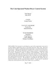
Resistors for Analog and Digital I/O<br />
The digital I/O points have a 100K Ω resistor to ground to prevent floating inputs.<br />
TO DIGITAL I/O<br />
The analog inputs have a two 560 ohm resistors in series to convert the 0 to 10 volt input<br />
to the 5 volt mpu input..<br />
TERMINAL STRIP PINOUTS<br />
DIGITAL<br />
BIT 0<br />
BIT 1<br />
BIT 2<br />
BIT 3<br />
BIT 4<br />
BIT 5<br />
BIT 6<br />
BIT 7<br />
PULSE CNT<br />
PWM<br />
GND<br />
GND<br />
+ 5VDC<br />
+ 5VDC<br />
+ UNREG<br />
TB2<br />
ANALOG INPUT<br />
560 OHM<br />
TO MPU ANALOG INPUT<br />
560 OHM<br />
TO MPU DIGITAL I/O<br />
100K OHM<br />
COMM PORT<br />
TB3<br />
ANALOG<br />
+UNREG<br />
+ 5VDC<br />
+ 5VDC<br />
GND<br />
GND<br />
GND<br />
GND<br />
CHAN 7<br />
CHAN 6<br />
CHAN 5<br />
CHAN 4<br />
CHAN 3<br />
CHAN 2<br />
CHAN 1<br />
CHAN 0
Integrity Instruments <strong>232M100</strong> Series User Manual<br />
Hex Conversion Chart<br />
BI<br />
T<br />
S<br />
H<br />
E<br />
X<br />
EXAMPLE HEX CONVERSION<br />
X X Y Y<br />
1 1 0 0 1 0 0 0 1 0 1 1 0 1 1 1<br />
C 8 B 7<br />
PORT 1 PORT 2<br />
X X Y Y<br />
H BIT H BIT H BIT H BIT<br />
E VALUE E VALUE E VALUE E VALUE<br />
X<br />
X<br />
X<br />
X<br />
V 7 6 5 4 V 3 2 1 0 V 7 6 5 4 V 3 2 1 0<br />
A<br />
A<br />
A<br />
A<br />
L<br />
L<br />
L<br />
L<br />
U<br />
U<br />
U<br />
U<br />
E<br />
E<br />
E<br />
E<br />
0 0 0 0 0 0 0 0 0 0 0 0 0 0 0 0 0 0 0 0<br />
1 0 0 0 1 1 0 0 0 1 1 0 0 0 1 1 0 0 0 1<br />
2 0 0 1 0 2 0 0 1 0 2 0 0 1 0 2 0 0 1 0<br />
3 0 0 1 1 3 0 0 1 1 3 0 0 1 1 3 0 0 1 1<br />
4 0 1 0 0 4 0 1 0 0 4 0 1 0 0 4 0 1 0 0<br />
5 0 1 0 1 5 0 1 0 1 5 0 1 0 1 5 0 1 0 1<br />
6 0 1 1 0 6 0 1 1 0 6 0 1 1 0 6 0 1 1 0<br />
7 0 1 1 1 7 0 1 1 1 7 0 1 1 1 7 0 1 1 1<br />
8 1 0 0 0 8 1 0 0 0 8 1 0 0 0 8 1 0 0 0<br />
9 1 0 0 1 9 1 0 0 1 9 1 0 0 1 9 1 0 0 1<br />
A 1 0 1 0 A 1 0 1 0 A 1 0 1 0 A 1 0 1 0<br />
B 1 0 1 1 B 1 0 1 1 B 1 0 1 1 B 1 0 1 1<br />
C 1 1 0 0 C 1 1 0 0 C 1 1 0 0 C 1 1 0 0<br />
D 1 1 0 1 D 1 1 0 1 D 1 1 0 1 D 1 1 0 1<br />
E 1 1 1 0 E 1 1 1 0 E 1 1 1 0 E 1 1 1 0<br />
F 1 1 1 1 F 1 1 1 1 F 1 1 1 1 F 1 1 1 1<br />
21
22<br />
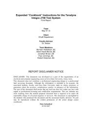
Integrity Instruments <strong>232M100</strong> Series User Manual<br />
GND<br />
DTR<br />
CTS<br />
TD<br />
RTS<br />
RD<br />
DSR<br />
Digital<br />
I/O<br />
LED<br />
COMMUNICATION PORT ON<br />
BOARD WIRING<br />
5<br />
9<br />
4<br />
8<br />
3<br />
7<br />
2<br />
6<br />
1<br />
DB9F<br />
Model <strong>232M100</strong> Series<br />
Communications<br />
Power/Port<br />
TB2<br />
Analog<br />
Input TB3<br />
U1<br />
DIP switch<br />
J1<br />
Power<br />
Baud Rate Switch Settings<br />
POWER CONNECTIONS ON<br />
BOARD WIRING<br />
+ VDC<br />
GND<br />
+ VDC<br />
GND<br />
U2<br />
SW1 SW2 Baud Rate<br />
OFF OFF 9600 baud<br />
ON OFF 19200 baud<br />
OFF ON 57600 baud<br />
ON ON 115200 baud<br />
(factory default)<br />
1<br />
2<br />
TB1<br />
1<br />
2<br />
J1<br />
Power 2.5mm
Integrity Instruments <strong>232M100</strong> Series User Manual<br />
IC 232M300 I/O <strong>Module</strong><br />
U1 PIC16F874A MPU [40 pin dip]<br />
U3 RS-232 driver [16 pin DIP]<br />
LED Operation<br />
Blinking Green [1 per Second] Unit functioning correctly - idle<br />
Blinking Green [Rapid or Steady] Unit receiving serial data<br />
Blinking Red [Rapid or Steady] Unit transmitting serial data<br />
No LED Unit is not functioning<br />
Power Supply<br />
7.5-15.0 Vdc approx. 50 ma. nominal power, 24 Vdc maximum 100 ma current draw (we<br />
suggest our PS9J a 9VDC 400 ma unregulated power supply)<br />
GND and Shield<br />
The GND and Shield terminals are connected on the 232M300 Series boards and are<br />
therefore electrically equivalent.<br />
RS-232 Cabling<br />
The RS-232 interface uses a “3 wire” RS-232 connection. That is to say only three wires<br />
are connected between the I/O <strong>Module</strong> and the Host PC: TxD, RxD and GND.<br />
RS-232 Flow Control<br />
The Integrity Instruments modules do not support hardware or Xon/Xoff flow control.<br />
23
24<br />
Integrity Instruments <strong>232M100</strong> Series User Manual<br />
Peripheral Add-On <strong>Module</strong>s<br />
The EXP-X expander unit provides for digital interface and signal conditioning via industry<br />
standard opto-isolated I/O modules such as Opto-22. Each unit has 4 I/O points with large<br />
easy to use terminal screws. If more I/O points are required, simply plug in another unit<br />
up to 8 total I/O points may be used the <strong>232M100</strong> module.. Opto isolated modules:<br />
90V-140V AC input, 12V-140V AC output, 3.3V-32V DC input, 3V-60V DC output.<br />
You will have to use our DB25TSF adapter to wire from the terminal strip of the <strong>232M100</strong><br />
unit to the expander module.<br />
WARRANTY<br />
Integrity Instruments warranties all products against defective workmanship and<br />
components for the life of the unit. Integrity Instruments agrees to repair or replace, at<br />
it’s sole discretion, a defective product if returned to Integrity Instruments with proof of<br />
purchase. Products that have been mis-used, improperly applied, or subject to adverse<br />
operating conditions fall beyond the realm of defective workmanship and are not<br />
convered by this warranty.<br />
Copyright © 2000-2003, Integrity Instruments, Inc.<br />
All trademarks and/or registered trademarks are the property of their respective owners.<br />
Revision: August 24, 2005 - v3.0