4536 24 Bit Timer.pdf
4536 24 Bit Timer.pdf
4536 24 Bit Timer.pdf

Create successful ePaper yourself
Turn your PDF publications into a flip-book with our unique Google optimized e-Paper software.
SEMICONDUCTOR TECHNICAL DATA<br />
<br />
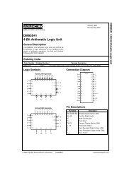
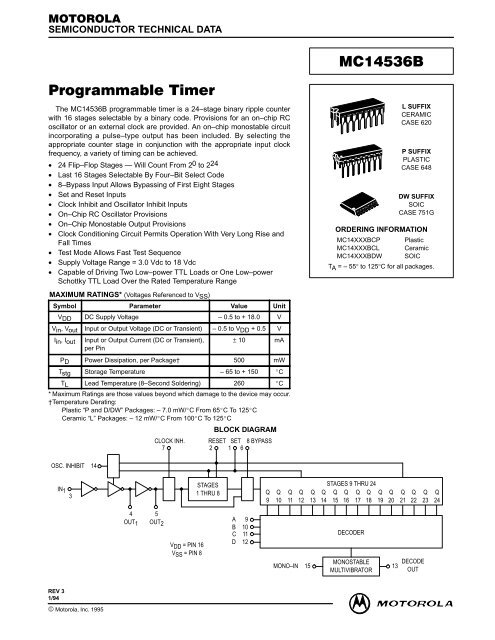
The MC1<strong>4536</strong>B programmable timer is a <strong>24</strong>–stage binary ripple counter<br />
with 16 stages selectable by a binary code. Provisions for an on–chip RC<br />
oscillator or an external clock are provided. An on–chip monostable circuit<br />
incorporating a pulse–type output has been included. By selecting the<br />
appropriate counter stage in conjunction with the appropriate input clock<br />
frequency, a variety of timing can be achieved.<br />
• <strong>24</strong> Flip–Flop Stages — Will Count From 20 to 2<strong>24</strong><br />
• Last 16 Stages Selectable By Four–<strong>Bit</strong> Select Code<br />
• 8–Bypass Input Allows Bypassing of First Eight Stages<br />
• Set and Reset Inputs<br />
• Clock Inhibit and Oscillator Inhibit Inputs<br />
• On–Chip RC Oscillator Provisions<br />
• On–Chip Monostable Output Provisions<br />
• Clock Conditioning Circuit Permits Operation With Very Long Rise and<br />
Fall Times<br />
• Test Mode Allows Fast Test Sequence<br />
• Supply Voltage Range = 3.0 Vdc to 18 Vdc<br />
• Capable of Driving Two Low–power TTL Loads or One Low–power<br />
Schottky TTL Load Over the Rated Temperature Range<br />
MAXIMUM RATINGS* (Voltages Referenced to VSS)<br />
ÎÎÎÎÎÎÎÎÎÎÎÎÎÎÎÎÎÎÎÎÎ<br />
ÎÎÎÎÎÎÎÎÎÎÎÎÎÎÎÎÎÎÎÎÎ<br />
ÎÎÎÎÎÎÎÎÎÎÎÎÎÎÎÎÎÎÎÎÎ<br />
Symbol Parameter Value Unit<br />
ÎÎÎÎÎÎÎÎÎÎÎÎÎÎÎÎÎÎÎÎÎ<br />
VDD DC Supply Voltage – 0.5 to + 18.0 V<br />
Vin, Vout Input or Output Voltage (DC or Transient) – 0.5 to VDD + 0.5 V<br />
Iin, Iout Input or Output Current (DC or Transient),<br />
per Pin<br />
© MOTOROLA Motorola, Inc. 1995 CMOS LOGIC DATA<br />
± 10 mA<br />
PD Power Dissipation, per Package† 500 mW<br />
Tstg Storage Temperature – 65 to + 150 C<br />
TL Lead Temperature (8–Second Soldering) 260 C<br />
* Maximum Ratings are those values beyond which damage to the device may occur.<br />
†Temperature Derating:<br />
Plastic “P and D/DW” Packages: – 7.0 mW/C From 65C To 125C<br />
Ceramic “L” Packages: – 12 mW/C From 100C To 125C<br />
OSC. INHIBIT 14<br />
REV 3<br />
1/94<br />
IN1<br />
3<br />
4<br />
OUT1<br />
BLOCK DIAGRAM<br />
CLOCK INH. RESET SET 8 BYPASS<br />
7 2 1 6<br />
5<br />
OUT2<br />
VDD = PIN 16<br />
VSS = PIN 8<br />
STAGES<br />
1 THRU 8<br />
A 9<br />
B 10<br />
C 11<br />
D 12<br />
Q<br />
9<br />
Q<br />
10<br />
Q<br />
11<br />
Q<br />
12<br />
MONO–IN 15<br />
Q<br />
13<br />
Q<br />
14<br />
STAGES 9 THRU <strong>24</strong><br />
Q<br />
15<br />
<br />
Q<br />
16<br />
Q<br />
17<br />
DECODER<br />
Q<br />
18<br />
MONOSTABLE<br />
MULTIVIBRATOR<br />
Q<br />
19<br />
Q<br />
20<br />
13<br />
L SUFFIX<br />
CERAMIC<br />
CASE 620<br />
P SUFFIX<br />
PLASTIC<br />
CASE 648<br />
DW SUFFIX<br />
SOIC<br />
CASE 751G<br />
ORDERING INFORMATION<br />
MC14XXXBCP Plastic<br />
MC14XXXBCL Ceramic<br />
MC14XXXBDW SOIC<br />
TA = – 55° to 125°C for all packages.<br />
Q<br />
21<br />
Q<br />
22<br />
DECODE<br />
OUT<br />
Q<br />
23<br />
Q<br />
<strong>24</strong><br />
MC1<strong>4536</strong>B<br />
1
ELECTRICAL CHARACTERISTICS (Voltages Referenced to VSS)<br />
ÎÎÎÎÎÎÎÎÎÎÎÎÎÎÎÎÎÎÎÎÎÎÎÎÎÎÎÎÎÎÎÎÎÎ<br />
ÎÎÎÎÎÎÎÎÎÎÎÎÎÎÎÎÎÎÎÎÎÎÎÎÎÎÎÎÎÎÎÎÎÎ<br />
ÎÎÎÎÎÎÎÎÎÎÎÎÎÎÎÎÎÎÎÎÎÎÎÎÎÎÎÎÎÎÎÎÎÎ<br />
ÎÎÎÎÎÎÎÎÎÎÎÎÎÎÎÎÎÎÎÎÎÎÎÎÎÎÎÎÎÎÎÎÎÎ<br />
Characteristic Symbol<br />
Unit<br />
Output Voltage “0” Level<br />
Vin = VDD or 0<br />
Vin = 0 or VDD<br />
MC1<strong>4536</strong>B<br />
2<br />
“1” Level<br />
Input Voltage “0” Level<br />
(VO = 4.5 or 0.5 Vdc)<br />
(VO = 9.0 or 1.0 Vdc)<br />
(VO = 13.5 or 1.5 Vdc)<br />
(VO = 0.5 or 4.5 Vdc)<br />
(VO = 1.0 or 9.0 Vdc)<br />
(VO = 1.5 or 13.5 Vdc)<br />
“1” Level<br />
Output Drive Current<br />
(VOH = 2.5 Vdc) Source<br />
(VOH = 4.6 Vdc) Pins 4 & 5<br />
(VOH = 9.5 Vdc)<br />
(VOH = 13.5 Vdc)<br />
(VOH = 2.5 Vdc) Source<br />
(VOH = 4.6 Vdc) Pin 13<br />
(VOH = 9.5 Vdc)<br />
(VOH = 13.5 Vdc)<br />
(VOL = 0.4 Vdc) Sink<br />
(VOL = 0.5 Vdc)<br />
(VOL = 1.5 Vdc)<br />
VOL<br />
VOH<br />
VIL<br />
VIH<br />
IOH<br />
IOL<br />
– 55C 25C 125C<br />
VDD VDD<br />
Vdc Min Max Min Typ # Max Min Max Unit<br />
5.0<br />
10<br />
15<br />
5.0<br />
10<br />
15<br />
5.0<br />
10<br />
15<br />
5.0<br />
10<br />
15<br />
5.0<br />
5.0<br />
10<br />
15<br />
5.0<br />
5.0<br />
10<br />
15<br />
5.0<br />
10<br />
15<br />
—<br />
—<br />
—<br />
4.95<br />
9.95<br />
14.95<br />
—<br />
—<br />
—<br />
3.5<br />
7.0<br />
11<br />
– 1.2<br />
– 0.25<br />
– 0.62<br />
– 1.8<br />
– 3.0<br />
– 0.64<br />
– 1.6<br />
– 4.2<br />
0.64<br />
1.6<br />
4.2<br />
0.05<br />
0.05<br />
0.05<br />
—<br />
—<br />
—<br />
1.5<br />
3.0<br />
4.0<br />
—<br />
—<br />
—<br />
—<br />
—<br />
—<br />
—<br />
—<br />
—<br />
—<br />
—<br />
—<br />
—<br />
—<br />
4.95<br />
9.95<br />
14.95<br />
—<br />
—<br />
—<br />
3.5<br />
7.0<br />
11<br />
– 1.0<br />
– 0.25<br />
– 0.5<br />
– 1.5<br />
– 2.4<br />
– 0.51<br />
– 1.3<br />
– 3.4<br />
0<br />
0<br />
0<br />
5.0<br />
10<br />
15<br />
2.25<br />
4.50<br />
6.75<br />
2.75<br />
5.50<br />
8.25<br />
– 1.7<br />
– 0.36<br />
– 0.9<br />
– 3.5<br />
– 4.2<br />
– 0.88<br />
– 2.25<br />
– 8.8<br />
0.05<br />
0.05<br />
0.05<br />
—<br />
—<br />
—<br />
1.5<br />
3.0<br />
4.0<br />
—<br />
—<br />
—<br />
—<br />
—<br />
—<br />
—<br />
—<br />
—<br />
—<br />
—<br />
—<br />
—<br />
—<br />
4.95<br />
9.95<br />
14.95<br />
—<br />
—<br />
—<br />
3.5<br />
7.0<br />
11<br />
– 0.7<br />
– 0.14<br />
– 0.35<br />
– 1.1<br />
– 1.7<br />
– 0.36<br />
– 0.9<br />
– 2.4<br />
Input Current Iin 15 — ±0.1 — ±0.00001 ±0.1 — ±1.0 μAdc<br />
Input Capacitance<br />
(Vin = 0)<br />
Quiescent Current<br />
(Per Package)<br />
Total Supply Current**†<br />
(Dynamic plus Quiescent,<br />
Per Package)<br />
(CL = 50 pF on all outputs, all<br />
buffers switching)<br />
—<br />
—<br />
—<br />
0.51<br />
1.3<br />
3.4<br />
0.88<br />
2.25<br />
8.8<br />
0.05<br />
0.05<br />
0.05<br />
Cin — — — — 5.0 7.5 — — pF<br />
IDD<br />
IT<br />
5.0<br />
10<br />
15<br />
5.0<br />
10<br />
15<br />
—<br />
—<br />
—<br />
5.0<br />
10<br />
20<br />
—<br />
—<br />
—<br />
0.010<br />
0.020<br />
0.030<br />
—<br />
—<br />
—<br />
5.0<br />
10<br />
20<br />
IT = (1.50 μA/kHz) f + IDD<br />
IT = (2.30 μA/kHz) f + IDD<br />
IT = (3.55 μA/kHz) f + IDD<br />
#Data labelled “Typ” is not to be used for design purposes but is intended as an indication of the IC’s potential performance.<br />
** The formulas given are for the typical characteristics only at 25C.<br />
†To calculate total supply current at loads other than 50 pF:<br />
IT(CL) = IT(50 pF) + (CL – 50) Vfk<br />
where: IT is in μA (per package), CL in pF, V = (VDD – VSS) in volts, f in kHz is input frequency, and k = 0.003.<br />
0.36<br />
0.9<br />
2.4<br />
—<br />
—<br />
—<br />
—<br />
—<br />
—<br />
1.5<br />
3.0<br />
4.0<br />
—<br />
—<br />
—<br />
—<br />
—<br />
—<br />
—<br />
—<br />
—<br />
—<br />
—<br />
—<br />
—<br />
—<br />
150<br />
300<br />
600<br />
Vdc<br />
Vdc<br />
Vdc<br />
Vdc<br />
mAdc<br />
mAdc<br />
mAdc<br />
μAdc<br />
μAdc<br />
MOTOROLA CMOS LOGIC DATA
SWITCHING CHARACTERISTICS* (CL = 50 pF, TA = 25C)<br />
ÎÎÎÎÎÎÎÎÎÎÎÎÎÎÎÎÎÎÎÎÎÎÎÎÎÎÎÎÎÎÎÎÎÎ<br />
ÎÎÎÎÎÎÎÎÎÎÎÎÎÎÎÎÎÎÎÎÎÎÎÎÎÎÎÎÎÎÎÎÎÎ<br />
ÎÎÎÎÎÎÎÎÎÎÎÎÎÎÎÎÎÎÎÎÎÎÎÎÎÎÎÎÎÎÎÎÎÎ<br />
ÎÎÎÎÎÎÎÎÎÎÎÎÎÎÎÎÎÎÎÎÎÎÎÎÎÎÎÎÎÎÎÎÎÎ<br />
Output Rise and Fall Time (Pin 13)<br />
ns<br />
MOTOROLA CMOS LOGIC DATA<br />
Characteristic Symbol VDD Min Typ # Max Unit<br />
tTLH, tTHL = (1.5 ns/pF) CL + 25 ns<br />
tTLH, tTHL = (0.75 ns/pF) CL + 12.5 ns<br />
tTLH, tTHL = (0.55 ns/pF) CL + 9.5 ns<br />
Propagation Delay Time<br />
Clock to Q1, 8–Bypass (Pin 6) High<br />
tPLH, tPHL = (1.7 ns/pF) CL + 1715 ns<br />
tPLH, tPHL = (0.66 ns/pF) CL + 617 ns<br />
tPLH, tPHL = (0.5 ns/pF) CL + 425 ns<br />
Clock to Q1, 8–Bypass (Pin 6) Low<br />
tPLH, tPHL = (1.7 ns/pF) CL + 3715 ns<br />
tPLH, tPHL = (0.66 ns/pF) CL + 1467 ns<br />
tPLH, tPHL = (0.5 ns/pF) CL + 1075 ns<br />
Clock to Q16<br />
tPHL, tPLH = (1.7 ns/pF) CL + 6915 ns<br />
tPHL, tPLH = (0.66 ns/pF) CL + 2967 ns<br />
tPHL, tPLH = (0.5 ns/pF) CL + 2175 ns<br />
Reset to Qn<br />
tPHL = (1.7 ns/pF) CL + 1415 ns<br />
tPHL = (0.66 ns/pF) CL + 567 ns<br />
tPHL = (0.5 ns/pF) CL + 425 ns<br />
tTLH,<br />
tTHL<br />
tPLH,<br />
tPHL<br />
tPLH,<br />
tPHL<br />
tPLH,<br />
tPHL<br />
tPHL<br />
Clock Pulse Width tWH 5.0<br />
10<br />
15<br />
Clock Pulse Frequency<br />
(50% Duty Cycle)<br />
Clock Rise and Fall Time tTLH,<br />
tTHL<br />
Reset Pulse Width tWH 5.0<br />
10<br />
15<br />
fcl<br />
5.0<br />
10<br />
15<br />
5.0<br />
10<br />
15<br />
5.0<br />
10<br />
15<br />
5.0<br />
10<br />
15<br />
5.0<br />
10<br />
15<br />
5.0<br />
10<br />
15<br />
5.0<br />
10<br />
15<br />
—<br />
—<br />
—<br />
—<br />
—<br />
—<br />
—<br />
—<br />
—<br />
—<br />
—<br />
—<br />
—<br />
—<br />
—<br />
600<br />
200<br />
170<br />
—<br />
—<br />
—<br />
100<br />
50<br />
40<br />
1800<br />
650<br />
450<br />
3.8<br />
1.5<br />
1.1<br />
7.0<br />
3.0<br />
2.2<br />
1500<br />
600<br />
450<br />
300<br />
100<br />
85<br />
1.2<br />
3.0<br />
5.0<br />
No Limit<br />
* The formulas given are for the typical characteristics only at 25C.<br />
#Data labelled “Typ” is not to be used for design purposes but is intended as an indication of the IC’s potential performance.<br />
This device contains protection circuitry to guard against damage<br />
due to high static voltages or electric fields. However, precautions must<br />
be taken to avoid applications of any voltage higher than maximum rated<br />
voltages to this high-impedance circuit. For proper operation, Vin and<br />
Vout should be constrained to the range VSS ≤ (Vin or Vout) ≤ VDD.<br />
Unused inputs must always be tied to an appropriate logic voltage<br />
level (e.g., either VSS or VDD). Unused outputs must be left open.<br />
1000<br />
400<br />
300<br />
500<br />
200<br />
150<br />
200<br />
100<br />
80<br />
3600<br />
1300<br />
1000<br />
7.6<br />
3.0<br />
2.3<br />
14<br />
6.0<br />
4.5<br />
3000<br />
1200<br />
900<br />
—<br />
—<br />
—<br />
0.4<br />
1.5<br />
2.0<br />
—<br />
—<br />
—<br />
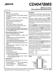
PIN ASSIGNMENT<br />
SET<br />
RESET<br />
IN 1<br />
OUT 1<br />
OUT 2<br />
8–BYPASS<br />
CLOCK INH<br />
VSS<br />
1<br />
2<br />
3<br />
4<br />
5<br />
6<br />
7<br />
8<br />
16<br />
15<br />
14<br />
13<br />
12<br />
11<br />
10<br />
9<br />
VDD<br />
D<br />
ns<br />
μs<br />
μs<br />
ns<br />
ns<br />
MHz<br />
—<br />
ns<br />
MONO IN<br />
OSC INH<br />
DECODE<br />
C<br />
B<br />
A<br />
MC1<strong>4536</strong>B<br />
3
INPUTS<br />
SET (Pin 1) — A high on Set asynchronously forces<br />
Decode Out to a high level. This is accomplished by setting<br />
an output conditioning latch to a high level while at the same<br />
time resetting the <strong>24</strong> flip–flop stages. After Set goes low<br />
(inactive), the occurrence of the first negative clock transition<br />
on IN1 causes Decode Out to go low. The counter’s flip–flop<br />
stages begin counting on the second negative clock transition<br />
of IN1. When Set is high, the on–chip RC oscillator is<br />
disabled. This allows for very low–power standby operation.<br />
RESET (Pin 2) — A high on Reset asynchronously forces<br />
Decode Out to a low level; all <strong>24</strong> flip–flop stages are also<br />
reset to a low level. Like the Set input, Reset disables the<br />
on–chip RC oscillator for standby operation.<br />
IN1 (Pin 3) — The device’s internal counters advance on<br />
the negative–going edge of this input. IN1 may be used as an<br />
external clock input or used in conjunction with OUT1 and<br />
OUT2 to form an RC oscillator. When an external clock is<br />
used, both OUT1 and OUT2 may be left unconnected or<br />
used to drive 1 LSTTL or several CMOS loads.<br />
8–BYPASS (Pin 6) — A high on this input causes the first<br />
8 flip–flop stages to be bypassed. This device essentially becomes<br />
a 16–stage counter with all 16 stages selectable.<br />
Selection is accomplished by the A, B, C, and D inputs. (See<br />
the truth tables.)<br />
CLOCK INHIBIT (Pin 7) — A high on this input disconnects<br />
the first counter stage from the clocking source. This<br />
holds the present count and inhibits further counting. However,<br />
the clocking source may continue to run. Therefore,<br />
when Clock Inhibit is brought low, no oscillator start–up time<br />
is required. When Clock Inhibit is low, the counter will start<br />
counting on the occurrence of the first negative edge of the<br />
clocking source at IN1.<br />
MC1<strong>4536</strong>B<br />
4<br />
PIN DESCRIPTIONS<br />
OSC INHIBIT (Pin 14) — A high level on this pin stops the<br />
RC oscillator which allows for very low–power standby operation.<br />
May also be used, in conjunction with an external<br />
clock, with essentially the same results as the Clock Inhibit<br />
input.<br />
MONO–IN (Pin 15) — Used as the timing pin for the on–<br />
chip monostable multivibrator. If the Mono–In input is connected<br />
to VSS, the monostable circuit is disabled, and<br />
Decode Out is directly connected to the selected Q output.<br />
The monostable circuit is enabled if a resistor is connected<br />
between Mono–In and VDD. This resistor and the device’s internal<br />
capacitance will determine the minimum output pulse<br />
widths. With the addition of an external capacitor to VSS, the<br />
pulse width range may be extended. For reliable operation<br />
the resistor value should be limited to the range of 5 kΩ to<br />
100 kΩ and the capacitor value should be limited to a maximum<br />
of 1000 pf. (See figures 3, 4, 5, and 10).<br />
A, B, C, D (Pins 9, 10, 11, 12) — These inputs select the<br />
flip–flop stage to be connected to Decode Out. (See the truth<br />
tables.)<br />
OUTPUTS<br />
OUT1, OUT2 (Pin 4, 5) — Outputs used in conjunction with<br />
IN1 to form an RC oscillator. These outputs are buffered and<br />
may be used for 20 frequency division of an external clock.<br />
DECODE OUT (Pin 13) — Output function depends on<br />
configuration. When the monostable circuit is disabled, this<br />
output is a 50% duty cycle square wave during free run.<br />
TEST MODE<br />
The test mode configuration divides the <strong>24</strong> flip–flop stages<br />
into three 8–stage sections to facilitate a fast test sequence.<br />
The test mode is enabled when 8–Bypass, Set and Reset<br />
are at a high level. (See Figure 8.)<br />
MOTOROLA CMOS LOGIC DATA
Input<br />
8–Bypass D C B A<br />
MOTOROLA CMOS LOGIC DATA<br />
Stage Stage Selected<br />
for Decode Out<br />
0 0 0 0 0 9<br />
0 0 0 0 1 10<br />
0 0 0 1 0 11<br />
0 0 0 1 1 12<br />
0 0 1 0 0 13<br />
0 0 1 0 1 14<br />
0 0 1 1 0 15<br />
0 0 1 1 1 16<br />
0 1 0 0 0 17<br />
0 1 0 0 1 18<br />
0 1 0 1 0 19<br />
0 1 0 1 1 20<br />
0 1 1 0 0 21<br />
0 1 1 0 1 22<br />
0 1 1 1 0 23<br />
0 1 1 1 1 <strong>24</strong><br />
In1 Set Reset<br />
TRUTH TABLES<br />
FUNCTION TABLE<br />
Clock<br />
Inh<br />
Input<br />
8–Bypass D C B A<br />
Stage Selected<br />
for Decode Out<br />
1 0 0 0 0 1<br />
1 0 0 0 1 2<br />
1 0 0 1 0 3<br />
1 0 0 1 1 4<br />
1 0 1 0 0 5<br />
1 0 1 0 1 6<br />
1 0 1 1 0 7<br />
1 0 1 1 1 8<br />
1 1 0 0 0 9<br />
1 1 0 0 1 10<br />
1 1 0 1 0 11<br />
1 1 0 1 1 12<br />
1 1 1 0 0 13<br />
1 1 1 0 1 14<br />
1 1 1 1 0 15<br />
1 1 1 1 1 16<br />
OSC<br />
Inh Out 1 Out 2<br />
Decode<br />
Out<br />
0 0 0 0 No<br />
Change<br />
0 0 0 0 Advance to<br />
next state<br />
X 1 0 0 0 0 1 1<br />
X 0 1 0 0 0 1 0<br />
X 0 0 1 0 — — No<br />
Change<br />
X 0 0 0 1 0 1 No<br />
Change<br />
0 0 0 0 X 0 1 No<br />
Change<br />
1 0 0 0 Advance to<br />
next state<br />
X = Don’t Care<br />
MC1<strong>4536</strong>B<br />
5
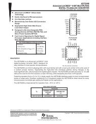
MC1<strong>4536</strong>B<br />
6<br />
8–BYPASS<br />
6<br />
RESET<br />
2<br />
OSC INHIBIT<br />
14<br />
LOGIC DIAGRAM<br />
<strong>24</strong><br />
STAGES<br />
18 THRU<br />
23<br />
17<br />
16<br />
STAGES<br />
10 THRU<br />
15<br />
3<br />
T 9<br />
8<br />
STAGES<br />
2 THRU 7<br />
T 1<br />
IN 1<br />
OUT 2 5<br />
4<br />
OUT 1<br />
DECODER<br />
A 9<br />
B 10<br />
C 11<br />
D 12<br />
C S<br />
Q<br />
R<br />
En<br />
DECODER<br />
OUT<br />
13<br />
SET<br />
7<br />
CLOCK<br />
INHIBIT<br />
1<br />
VDD = PIN 16<br />
VSS = PIN 8<br />
15<br />
MONO–IN<br />
MOTOROLA CMOS LOGIC DATA
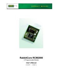
FREQUENCY DEVIATION (%)<br />
μs)<br />
, PULSE WIDTH (<br />
t W<br />
8.0<br />
4.0<br />
0<br />
– 4.0<br />
– 8.0<br />
– 12<br />
RTC = 56 kΩ,<br />
C = 1000 pF<br />
– 16<br />
– 55 – 25 0<br />
RS = 0, f = 10.15 kHz @ VDD = 10 V, TA = 25°C<br />
RS = 120 kΩ, f = 7.8 kHz @ VDD = 10 V, TA = 25°C<br />
25 50 75 100 125<br />
* Device Only.<br />
100<br />
10<br />
1.0<br />
0.1<br />
1.0<br />
Figure 1. RC Oscillator Stability Figure 2. RC Oscillator Frequency as a<br />
Function of RTC and C<br />
MOTOROLA CMOS LOGIC DATA<br />
VDD = 15 V<br />
10 V<br />
5.0 V<br />
TA, AMBIENT TEMPERATURE (°C)*<br />
FORMULA FOR CALCULATING tW IN<br />
MICROSECONDS IS AS FOLLOWS:<br />
tW = 0.00<strong>24</strong>7 RX • CX 0.85<br />
WHERE R IS IN kΩ, CX IN pF.<br />
RX = 100 kΩ<br />
50 kΩ<br />
10 kΩ<br />
5 kΩ<br />
10<br />
100<br />
CX, EXTERNAL CAPACITANCE (pF)<br />
Figure 3. Typical CX versus Pulse Width<br />
@ VDD = 5.0 V<br />
μs)<br />
, PULSE WIDTH (<br />
t W<br />
TYPICAL RC OSCILLATOR CHARACTERISTICS<br />
(For Circuit Diagram See Figure 11 In Application)<br />
TA = 25°C<br />
VDD = 5 V<br />
1000<br />
f, OSCILLATOR FREQUENCY (kHz)<br />
100<br />
50<br />
20<br />
10<br />
5.0<br />
2.0<br />
1.0<br />
0.5<br />
0.2<br />
f AS A FUNCTION<br />
OF C<br />
(RTC = 56 kΩ)<br />
(RS = 120 k)<br />
MONOSTABLE CHARACTERISTICS<br />
(For Circuit Diagram See Figure 10 In Application)<br />
100<br />
10<br />
1.0<br />
0.1<br />
1.0<br />
μs)<br />
, PULSE WIDTH (<br />
t W<br />
VDD = 10 V<br />
f AS A FUNCTION<br />
OF RTC<br />
(C = 1000 pF)<br />
(RS ≈ 2RTC)<br />
0.1<br />
1.0 k 10 k 100 k<br />
RTC, RESISTANCE (OHMS)<br />
1.0 M<br />
0.0001 0.001 0.01 0.1<br />
C, CAPACITANCE (μF)<br />
100<br />
FORMULA FOR CALCULATING tW IN<br />
MICROSECONDS IS AS FOLLOWS:<br />
tW = 0.00<strong>24</strong>7 RX • CX 0.85<br />
WHERE R IS IN kΩ, CX IN pF.<br />
RX = 100 kΩ<br />
50 kΩ<br />
10<br />
1.0<br />
0.1<br />
1.0<br />
FORMULA FOR CALCULATING tW IN<br />
MICROSECONDS IS AS FOLLOWS:<br />
tW = 0.00<strong>24</strong>7 RX • CX 0.85<br />
WHERE R IS IN kΩ, CX IN pF.<br />
RX = 100 kΩ<br />
50 kΩ<br />
10<br />
100<br />
CX, EXTERNAL CAPACITANCE (pF)<br />
10 kΩ<br />
5 kΩ<br />
10 kΩ<br />
5 kΩ TA = 25°C<br />
VDD = 15 V<br />
Figure 5. Typical CX versus Pulse Width<br />
@ VDD = 15 V<br />
10<br />
100<br />
CX, EXTERNAL CAPACITANCE (pF)<br />
TA = 25°C<br />
VDD = 10 V<br />
Figure 4. Typical CX versus Pulse Width<br />
@ VDD = 10 V<br />
1000<br />
1000<br />
MC1<strong>4536</strong>B<br />
7
PULSE<br />
GENERATOR<br />
Figure 6. Power Dissipation Test<br />
Circuit and Waveform<br />
MC1<strong>4536</strong>B<br />
8<br />
500 μF I D<br />
SET<br />
RESET<br />
8–BYPASS<br />
IN 1<br />
C INH<br />
MONO IN<br />
OSC INH<br />
A<br />
B<br />
C<br />
D<br />
V DD<br />
OUT 1<br />
OUT<br />
2<br />
DECODE<br />
OUT<br />
V SS<br />
0.01 μF<br />
CERAMIC<br />
20 ns 20 ns<br />
90% 50%<br />
10%<br />
50%<br />
DUTY CYCLE<br />
FUNCTIONAL TEST SEQUENCE<br />
C L<br />
C L<br />
C L<br />
PULSE<br />
GENERATOR<br />
Test function (Figure 8) has been included for the reduction<br />
of test time required to exercise all <strong>24</strong> counter stages.<br />
This test function divides the counter into three 8–stage<br />
sections and 255 counts are loaded in each of the 8–stage<br />
sections in parallel. All flip–flops are now at a “1”. The counter<br />
is now returned to the normal <strong>24</strong>–stages in series configuration.<br />
One more pulse is entered into In1 which will cause<br />
the counter to ripple from an all “1” state to an all “0” state.<br />
SET<br />
RESET<br />
8–BYPASS<br />
IN 1<br />
C INH<br />
MONO IN<br />
OSC INH<br />
A<br />
B<br />
C<br />
D<br />
FUNCTIONAL TEST SEQUENCE<br />
V DD<br />
OUT 1<br />
OUT<br />
2<br />
DECODE<br />
OUT C L<br />
V SS<br />
20 ns<br />
IN 1<br />
OUT<br />
t PLH<br />
t WL<br />
90%<br />
10%<br />
t TLH<br />
20 ns<br />
50%<br />
t THL<br />
Figure 7. Switching Time Test Circuit and Waveforms<br />
PULSE<br />
GENERATOR<br />
Inputs Outputs Comments<br />
In1 Set Reset 8–Bypass<br />
1 0 1 1 0<br />
SET<br />
RESET<br />
8–BYPASS<br />
IN 1<br />
C INH<br />
MONO IN<br />
OSC INH<br />
A<br />
B<br />
C<br />
D<br />
V DD<br />
OUT 1<br />
OUT<br />
2<br />
DECODE<br />
OUT<br />
V SS<br />
Figure 8. Functional Test Circuit<br />
Decade Out<br />
Q1 thru Q<strong>24</strong> All <strong>24</strong> stages are in Reset mode. mode.<br />
1 1 1 1 0 Counter is in three 8 stage sections in parallel mode.<br />
0 1 1 1 0 First “1” to “0” transition of clock.<br />
1<br />
0<br />
—<br />
—<br />
—<br />
1 1 1 255 “1” to “0” transitions are clocked in the counter.<br />
0 1 1 1 1 The 255 “1” to “0” transition.<br />
0 0 0 0 1 Counter converted back to <strong>24</strong> stages in series mode.<br />
Set and Reset must be connected together and simultaneously<br />
go from “1” to “0”.<br />
1 0 0 0 1 In1 Switches to a “1”.<br />
0 0 0 0 0 Counter Ripples from an all “1” state to an all “0” state.<br />
t WH<br />
50%<br />
t PHL<br />
MOTOROLA CMOS LOGIC DATA
PULSE<br />
GEN.<br />
PULSE<br />
GEN.<br />
MOTOROLA CMOS LOGIC DATA<br />
CLOCK<br />
IN1<br />
SET<br />
CLOCK INH<br />
DECODE OUT<br />
POWER UP<br />
6<br />
8–BYPASS<br />
VDD<br />
9<br />
A<br />
OUT 1<br />
4<br />
10<br />
B<br />
11<br />
C<br />
12<br />
D<br />
2<br />
RESET<br />
OUT 2<br />
5<br />
14<br />
OSC INH<br />
15<br />
MONO–IN<br />
1<br />
SET<br />
7<br />
CLOCK INH<br />
3<br />
IN1 DECODE OUT<br />
VSS<br />
13<br />
NOTE: When power is first applied to the device, Decode Out can be either at a high or low state.<br />
On the rising edge of a Set pulse the output goes high if initially at a low state. The output<br />
remains high if initially at a high state. Because Clock Inh is held high, the clock source on<br />
the input pin has no effect on the output. Once Clock Inh is taken low, the output goes low<br />
on the first negative clock transition. The output returns high depending on the 8–Bypass,<br />
A, B, C, and D inputs, and the clock input period. A 2n frequency division (where n = the<br />
number of stages selected from the truth table) is obtainable at Decode Out. A 20–divided<br />
output of IN1 can be obtained at OUT1 and OUT2.<br />
Figure 9. Time Interval Configuration Using an External Clock, Set,<br />
and Clock Inhibit Functions<br />
(Divide–by–2 Configured)<br />
+V<br />
16<br />
8<br />
MC1<strong>4536</strong>B<br />
9
MC1<strong>4536</strong>B<br />
10<br />
PULSE<br />
GEN.<br />
CLOCK<br />
IN1<br />
RESET<br />
DECODE OUT<br />
POWER UP<br />
RX<br />
CX<br />
*tw<br />
6<br />
8–BYPASS<br />
VDD<br />
9<br />
A<br />
OUT 1<br />
4<br />
10<br />
B<br />
11<br />
C<br />
12<br />
D<br />
2<br />
RESET<br />
OUT 2<br />
5<br />
1<br />
SET<br />
7<br />
CLOCK INH<br />
15<br />
MONO–IN<br />
14<br />
CLOCK INH<br />
3<br />
IN1 DECODE OUT<br />
VSS<br />
13<br />
NOTE: When Power is first applied to the device with the Reset input going high, Decode Out initializes low. Bringing the Reset<br />
input low enables the chip’s internal counters. After Reset goes low, the 2n/2 negative transition of the clock input causes<br />
Decode Out to go high. Since the Mono–In input is being used, the output becomes monostable. The pulse width of the<br />
output is dependent on the external timing components. The second and all subsequent pulses occur at 2n x (the clock<br />
period) intervals where n = the number of stages selected from the truth table.<br />
Figure 10. Time Interval Configuration Using an External Clock, Reset,<br />
and Output Monostable to Achieve a Pulse Output<br />
(Divide–by–4 Configured)<br />
+V<br />
16<br />
8<br />
*tw ≈.00<strong>24</strong>7 • RX • CX0.85<br />
tw in μsec<br />
RX in kΩ<br />
CX in pF<br />
MOTOROLA CMOS LOGIC DATA
PULSE<br />
GEN.<br />
RESET<br />
OUT 1<br />
OUT 2<br />
DECODE OUT<br />
POWER UP<br />
NOTE: This circuit is designed to use the on–chip oscillation function. The oscillator frequency is determined<br />
by the external R and C components. When power is first applied to the device, Decode Out<br />
initializes to a high state. Because this output is tied directly to the Osc–Inh input, the oscillator is<br />
disabled. This puts the device in a low–current standby condition. The rising edge of the Reset pulse<br />
will cause the output to go low. This in turn causes Osc–Inh to go low. However, while Reset is high,<br />
the oscillator is still disabled (i.e.: standy condition). After Reset goes low, the output remains low<br />
for 2n/2 of the oscillator’s period. After the part times out, the output again goes high.<br />
MOTOROLA CMOS LOGIC DATA<br />
+V<br />
6<br />
8–BYPASS<br />
VDD<br />
9<br />
A<br />
OUT 1<br />
4<br />
10<br />
B<br />
C<br />
11<br />
C<br />
12<br />
2<br />
D<br />
RESET<br />
OUT 2<br />
5<br />
14<br />
15<br />
SET<br />
CLOCK INH<br />
1<br />
MONO–IN<br />
7<br />
CLOCK INH<br />
3<br />
IN1 DECODE OUT<br />
VSS<br />
13<br />
tw<br />
Figure 11. Time Interval Configuration Using On–Chip RC Oscillator and<br />
Reset Input to Initiate Time Interval<br />
(Divide–by–2 Configured)<br />
16<br />
8<br />
RS<br />
RTC<br />
fosc <br />
Rs ≥Rtc<br />
F = Hz<br />
R = Ohms<br />
C = FARADS<br />
1<br />
2.3Rtc C<br />
MC1<strong>4536</strong>B<br />
11
–T–<br />
SEATING<br />
PLANE<br />
16<br />
MC1<strong>4536</strong>B<br />
12<br />
F<br />
H<br />
–A–<br />
1 8<br />
G<br />
–A–<br />
16 9<br />
1 8<br />
E<br />
G<br />
D 16 PL<br />
0.25 (0.010) M T<br />
F<br />
9<br />
D 16 PL<br />
B<br />
S<br />
C<br />
K<br />
–B–<br />
0.25 (0.010) M T<br />
C<br />
N K<br />
A<br />
S<br />
SEATING<br />
–T– PLANE<br />
A<br />
OUTLINE DIMENSIONS<br />
L SUFFIX<br />
CERAMIC DIP PACKAGE<br />
CASE 620–10<br />
ISSUE V<br />
M<br />
P SUFFIX<br />
PLASTIC DIP PACKAGE<br />
CASE 648–08<br />
ISSUE R<br />
J<br />
L<br />
J 16 PL<br />
0.25 (0.010) M T B<br />
L<br />
M<br />
M<br />
S<br />
NOTES:<br />
1. DIMENSIONING AND TOLERANCING PER<br />
ANSI Y14.5M, 1982.<br />
2. CONTROLLING DIMENSION: INCH.<br />
3. DIMENSION L TO CENTER OF LEAD WHEN<br />
FORMED PARALLEL.<br />
4. DIMENSION F MAY NARROW TO 0.76 (0.030)<br />
WHERE THE LEAD ENTERS THE CERAMIC<br />
BODY.<br />
INCHES MILLIMETERS<br />
DIM MIN MAX MIN MAX<br />
A 0.750 0.785 19.05 19.93<br />
B 0.<strong>24</strong>0 0.295 6.10 7.49<br />
C ––– 0.200 ––– 5.08<br />
D 0.015 0.020 0.39 0.50<br />
E 0.050 BSC 1.27 BSC<br />
F 0.055 0.065 1.40 1.65<br />
G 0.100 BSC 2.54 BSC<br />
H 0.008 0.015 0.21 0.38<br />
K 0.125 0.170 3.18 4.31<br />
L 0.300 BSC 7.62 BSC<br />
M 0 15 0 15 <br />
N 0.020 0.040 0.51 1.01<br />
NOTES:<br />
1. DIMENSIONING AND TOLERANCING PER ANSI<br />
Y14.5M, 1982.<br />
2. CONTROLLING DIMENSION: INCH.<br />
3. DIMENSION L TO CENTER OF LEADS WHEN<br />
FORMED PARALLEL.<br />
4. DIMENSION B DOES NOT INCLUDE MOLD FLASH.<br />
5. ROUNDED CORNERS OPTIONAL.<br />
INCHES MILLIMETERS<br />
DIM MIN MAX MIN MAX<br />
A 0.740 0.770 18.80 19.55<br />
B 0.250 0.270 6.35 6.85<br />
C 0.145 0.175 3.69 4.44<br />
D 0.015 0.021 0.39 0.53<br />
F 0.040 0.70 1.02 1.77<br />
G 0.100 BSC 2.54 BSC<br />
H 0.050 BSC 1.27 BSC<br />
J 0.008 0.015 0.21 0.38<br />
K 0.110 0.130 2.80 3.30<br />
L 0.295 0.305 7.50 7.74<br />
M 0 10 0 10 <br />
S 0.020 0.040 0.51 1.01<br />
MOTOROLA CMOS LOGIC DATA
–A–<br />
16 9<br />
1<br />
16X D<br />
14X G<br />
MOTOROLA CMOS LOGIC DATA ◊<br />
–B– 8X P<br />
0.010 (0.25) M T A S B S<br />
8<br />
K<br />
C<br />
–T–<br />
SEATING<br />
PLANE<br />
OUTLINE DIMENSIONS<br />
DW SUFFIX<br />
PLASTIC SOIC PACKAGE<br />
CASE 751G–02<br />
ISSUE A<br />
0.010 (0.25) M<br />
J<br />
F<br />
M<br />
B<br />
M<br />
R X 45<br />
NOTES:<br />
1. DIMENSIONING AND TOLERANCING PER ANSI<br />
Y14.5M, 1982.<br />
2. CONTROLLING DIMENSION: MILLIMETER.<br />
3. DIMENSIONS A AND B DO NOT INCLUDE MOLD<br />
PROTRUSION.<br />
4. MAXIMUM MOLD PROTRUSION 0.15 (0.006) PER<br />
SIDE.<br />
5. DIMENSION D DOES NOT INCLUDE DAMBAR<br />
PROTRUSION. ALLOWABLE DAMBAR<br />
PROTRUSION SHALL BE 0.13 (0.005) TOTAL IN<br />
EXCESS OF D DIMENSION AT MAXIMUM<br />
MATERIAL CONDITION.<br />
MILLIMETERS INCHES<br />
DIM MIN MAX MIN MAX<br />
A 10.15 10.45 0.400 0.411<br />
B 7.40 7.60 0.292 0.299<br />
C 2.35 2.65 0.093 0.104<br />
D 0.35 0.49 0.014 0.019<br />
F 0.50 0.90 0.020 0.035<br />
G 1.27 BSC 0.050 BSC<br />
J 0.25 0.32 0.010 0.012<br />
K 0.10 0.25 0.004 0.009<br />
M 0 7 0 7 <br />
P 10.05 10.55 0.395 0.415<br />
R 0.25 0.75 0.010 0.029<br />
Motorola reserves the right to make changes without further notice to any products herein. Motorola makes no warranty, representation or guarantee regarding<br />
the suitability of its products for any particular purpose, nor does Motorola assume any liability arising out of the application or use of any product or circuit,<br />
and specifically disclaims any and all liability, including without limitation consequential or incidental damages. “Typical” parameters which may be provided<br />
in Motorola data sheets and/or specifications can and do vary in different applications and actual performance may vary over time. All operating parameters,<br />
including “Typicals” must be validated for each customer application by customer’s technical experts. Motorola does not convey any license under its patent<br />
rights nor the rights of others. Motorola products are not designed, intended, or authorized for use as components in systems intended for surgical implant<br />
into the body, or other applications intended to support or sustain life, or for any other application in which the failure of the Motorola product could create a<br />
situation where personal injury or death may occur. Should Buyer purchase or use Motorola products for any such unintended or unauthorized application,<br />
Buyer shall indemnify and hold Motorola and its officers, employees, subsidiaries, affiliates, and distributors harmless against all claims, costs, damages, and<br />
expenses, and reasonable attorney fees arising out of, directly or indirectly, any claim of personal injury or death associated with such unintended or<br />
unauthorized use, even if such claim alleges that Motorola was negligent regarding the design or manufacture of the part. Motorola and are registered<br />
trademarks of Motorola, Inc. Motorola, Inc. is an Equal Opportunity/Affirmative Action Employer.<br />
How to reach us:<br />
USA/EUROPE/Locations Not Listed: Motorola Literature Distribution; JAPAN: Nippon Motorola Ltd.; Tatsumi–SPD–JLDC, 6F Seibu–Butsuryu–Center,<br />
P.O. Box 20912; Phoenix, Arizona 85036. 1–800–441–<strong>24</strong>47 or 602–303–5454 3–14–2 Tatsumi Koto–Ku, Tokyo 135, Japan. 03–81–3521–8315<br />
MFAX: RMFAX0@email.sps.mot.com – TOUCHTONE 602–<strong>24</strong>4–6609 ASIA/PACIFIC: Motorola Semiconductors H.K. Ltd.; 8B Tai Ping Industrial Park,<br />
INTERNET: http://Design–NET.com 51 Ting Kok Road, Tai Po, N.T., Hong Kong. 852–26629298<br />
MC1<strong>4536</strong>B/D MC1<strong>4536</strong>B<br />
13
This datasheet has been download from:<br />
www.datasheetcatalog.com<br />
Datasheets for electronics components.