Charge Your Battery Faster By Using a USB Port - Power Electronics
Charge Your Battery Faster By Using a USB Port - Power Electronics
Charge Your Battery Faster By Using a USB Port - Power Electronics

You also want an ePaper? Increase the reach of your titles
YUMPU automatically turns print PDFs into web optimized ePapers that Google loves.
<strong>Charge</strong> <strong>Your</strong> <strong>Battery</strong> <strong>Faster</strong><br />
<strong>By</strong> <strong>Using</strong> a <strong>USB</strong> <strong>Port</strong><br />
Design considerations for battery charging from<br />
<strong>USB</strong> include how fast a device with a discharged<br />
battery must operate with full functionality when<br />
plugged into a <strong>USB</strong> port; time allowed for battery<br />
charging; power budgeting within <strong>USB</strong> limits; and<br />
the need for ac adapter charging.<br />
One of the best but least-celebrated features<br />
of the universal serial bus (<strong>USB</strong>)<br />
standard is that power is supplied from<br />
the host to plugged-in <strong>USB</strong> peripherals.<br />
This enlightened change from the<br />
serial and parallel ports of the past allows a dramatic<br />
increase in the variety of devices that can be conveniently<br />
connected to a PC.<br />
In addition to directly powering <strong>USB</strong> devices, one of<br />
the more useful functions to perform with <strong>USB</strong> power is<br />
battery charging. 1 Because many portable devices, such as<br />
MP3 players and PDAs, exchange information with PCs,<br />
device convenience is significantly enhanced if battery<br />
charging and data exchange take place simultaneously and<br />
over one cable. Combining <strong>USB</strong> and battery-powered functionality<br />
gives rise to a whole range of “untethered” devices,<br />
such as removable web cameras, that operate whether<br />
or not they are connected to a PC. In many cases, it’s no<br />
longer necessary to include the ever-present and awkward<br />
ac adapter or “wall wart.”<br />
<strong>USB</strong> <strong>Power</strong><br />
All <strong>USB</strong> host devices, such as PCs and notebooks, can<br />
source at least 500 mA or five “unit loads” per <strong>USB</strong> socket.<br />
In <strong>USB</strong> terminology, “one unit load” is 100 mA. Self-<br />
Host or<br />
powered hub<br />
Bus-powered hub<br />
4.640 V<br />
4.750 V 4.735 V 4.625 V *4.400 V<br />
4.500 V<br />
0.000 V<br />
0.015 V<br />
0.110 V<br />
0.125 V<br />
Referenced<br />
to source<br />
0.000 V<br />
Referenced<br />
to hub<br />
4.378 V<br />
4.397 V<br />
0.003 V<br />
0.022 V<br />
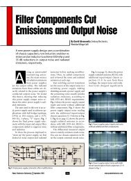
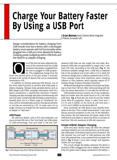
Fig. 1. <strong>USB</strong> voltage drops (from <strong>USB</strong> Specification Rev 2.0).<br />
4.375 V<br />
4.350 V<br />
0.025 V<br />
<strong>By</strong> Len en S SSher<br />
S her herman her man mman a n, Senior Scientist, Maxim Integrated<br />
Products, Sunnyvale, Calif.<br />
powered <strong>USB</strong> hubs can also supply five unit loads. Buspowered<br />
<strong>USB</strong> hubs are guaranteed to supply only 1 unit<br />
load (100 mA). According to the <strong>USB</strong> spec (Fig. 1), the<br />
minimum available voltage from a <strong>USB</strong> host or powered<br />
hub at the peripheral end of the cable is 4.5 V, while the<br />
minimum voltage from a <strong>USB</strong> bus-powered hub is 4.35 V.<br />
These voltages allow little headroom when charging<br />
Lithium (Li-Ion) batteries, which typically require 4.2 V,<br />
making charger dropout extremely important.<br />
All devices that plug into a <strong>USB</strong> port must start out drawing<br />
no more than 100 mA. After communicating with the<br />
host, the device determines if it can take the full 500 mA.<br />
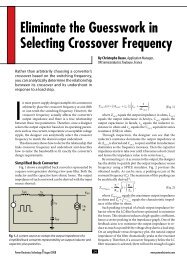
<strong>USB</strong> peripheral devices contain one of two receptacles.<br />
Both are smaller than the socket found in PCs and other<br />
<strong>USB</strong> hosts. Fig. 2 illustrates the Series B and the smaller<br />
Series Mini-B receptacles. <strong>Power</strong> is taken from pins 1<br />
(+5 V) and 4 (GND) on the Series B, and from pins 1<br />
(+5 V) and 5 (GND) on the Series Mini-B.<br />
Once connected, all <strong>USB</strong> devices must identify themselves<br />
to the host. This is called “enumeration.” Later, we’ll<br />
discuss practical exceptions to this rule. In the identification<br />
process, the host determines the power needs of the<br />
<strong>USB</strong> devices and allows or denies the device to increase its<br />
load from 100-mA maximum to 500-mA maximum.<br />
Simple <strong>USB</strong>/AC Adapter Charging<br />
Some very basic devices many not want the software<br />
overhead needed to sort out and optimize use of the available<br />
<strong>USB</strong> power. If the device load current is limited to 100<br />
mA (termed “one unit load” in <strong>USB</strong> parlance) any <strong>USB</strong><br />
host, self-powered hub, or bus-powered hub can power the<br />
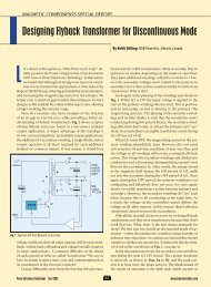
device. Fig. 3 shows a very basic charger and regulator<br />
scheme for such designs.<br />
This circuit charges the battery whenever the device is<br />
docked to <strong>USB</strong> or plugged into the ac adapter. At the same<br />
time, the system load is always connected to the battery—<br />
<strong>Power</strong> <strong>Electronics</strong> Technology January 2004 34<br />
www.powerelectronics.com
<strong>USB</strong> PORT<br />
VBus<br />
D - +5 V<br />
2 1<br />
3<br />
4<br />
D+ Gnd<br />
Series B<br />
<strong>USB</strong> device receptacles<br />
+5 V<br />
VBus D- D+ Nc Gnd<br />
12 34 5<br />
Series mini-B<br />
Fig. 2. These receptacles for <strong>USB</strong> peripherals differ from the large 4-pin<br />
sockets found on hosts and hubs. <strong>Power</strong> and data connection pins are<br />
shown.<br />
in this case, through a simple linear regulator (U2)—that<br />
can supply up to 200 mA. If the system continuously draws<br />
that amount of current while the battery is charging at 100<br />
mA from <strong>USB</strong>, the battery will still discharge because the<br />
load current exceeds the charge current. In most small systems,<br />
the peak loads occur only for a fraction of the total<br />
operating time. Thus, as long as the average load current is<br />
less than charging current, the battery will still charge.<br />
When the ac adapter is connected, the charger (U1) maximum<br />
current increases to 350 mA. If <strong>USB</strong> and the ac<br />
adapter are connected at the same time, the ac adapter is<br />
automatically given precedence.<br />
One characteristic of U1 that is required by the <strong>USB</strong> spec<br />
is that current is never allowed to flow back to a power input<br />
from either the battery or another power input. In conventional<br />
chargers, this can be guaranteed with input diodes,<br />
but the small difference between the minimum <strong>USB</strong> voltage<br />
(4.35 V) and the required Li-Ion battery voltage (4.2 V) makes<br />
even Schottky diodes inappropriate. For this reason, all<br />
reverse current paths are blocked within the U1 IC.<br />
The circuit shown in Fig. 3 has limitations that may make<br />
it inappropriate for some rechargeable <strong>USB</strong> devices. The<br />
most obvious is its relatively low charge current, which<br />
translates to long charge time if the Li-Ion battery capacity<br />
is more than a few hundred mA-hours. The second limitation<br />
occurs because the load (linear regulator input) is always<br />
connected to the battery. In this case, the system may<br />
not be able to operate immediately upon being plugged in<br />
if the battery is deeply discharged since there may be a delay<br />
before the battery reaches a sufficient voltage for the<br />
system to operate.<br />
Load Switching and Other Enhancements<br />
In more advanced systems, several enhancements are<br />
often required in or around the charger. These include selectable<br />
charge current to match the current capability of<br />
the source (<strong>USB</strong> or ac adapter) or battery, load switching<br />
when power is plugged in, and overvoltage protection. The<br />
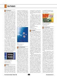
circuit shown in Fig. 4 adds some of these features by means<br />
of external MOSFETs driven by voltage detectors in the<br />
charger IC.<br />
MOSFETs Q1 and Q2 and diodes D1 and D2 bypass<br />
the battery and connect the active (<strong>USB</strong> or ac adapter)<br />
power input directly to the load. When a power input is<br />
valid, its monitor output (UOK\ or DCOK\) goes low to<br />
turn on the appropriate MOSFET. When both inputs are<br />
valid, the dc input has precedence; U1 prevents both inputs<br />
from being active at the same time. Diodes D1 and<br />
D2 prevent reverse current from flowing between inputs<br />
via the “system load” power path, while the charger has<br />
built-in circuitry to prevent reverse current through the<br />
charging path (at BATT).<br />
MOSFET Q2 also provides ac adapter overvoltage protection<br />
up to 18 V. An under/overvoltage monitor (at dc)<br />
allows charging only when the ac adapter voltage is between<br />
4 V and 6.25 V.<br />
The last MOSFET, Q3, turns on to connect the battery<br />
to the load when no valid external power is present. When<br />
either <strong>USB</strong> or dc power is connected, the <strong>Power</strong> On (PON)<br />
output immediately shuts off Q3 to disconnect the battery<br />
from the load. This allows the system to operate immediately<br />
when external power is applied, even if the battery is<br />
deeply discharged or damaged.<br />
When <strong>USB</strong> is connected, the <strong>USB</strong> device communicates<br />
with the host to determine if the load current can be increased.<br />
The load starts out at one unit load and is increased<br />
to five unit loads if the host allows it. This 5-to-1 current<br />
range can be problematic for conventional chargers (not<br />
designed for <strong>USB</strong>). The problem is that the current accuracy<br />
of conventional chargers, though adequate at high current,<br />
usually suffers at low current settings because of offsets<br />
in the current-sense circuitry. The result can be that<br />
the low-range (for one unit load) charge current may have<br />
to be set too low to be useful in order to ensure it never<br />
exceeds the 100-mA limit. For example, with 10% accuracy<br />
at 500 mA, the output would have to be set for 450<br />
mA to ensure it never exceeds 500 mA. That alone is acceptable.<br />
However, to ensure the low-range charge current<br />
doesn’t exceed 100 mA, the nominal current would have<br />
to be set at 50 mA, and the minimum could then be 0 mA,<br />
which clearly is unacceptable. If <strong>USB</strong> charging is to be<br />
effective in both ranges, sufficient accuracy is needed to<br />
allow the maximum possible typical charge current without<br />
exceeding the <strong>USB</strong> limits.<br />
In some designs, system power needs are such that it’s<br />
impractical to separately power the load and charge the<br />
battery with less than the 500-mA <strong>USB</strong> budget, but doing<br />
so from an ac adapter is not a problem. The connection in<br />
Fig. 5, a simplified subset of Fig. 4, does this in a costeffective<br />
way. <strong>USB</strong> power isn’t routed directly to the load.<br />
Both charging and system operation still take place on <strong>USB</strong><br />
power, but the system remains connected to the battery.<br />
The limitation is the same as in Fig. 3. If the battery is deeply<br />
discharged when <strong>USB</strong> is connected, there may be a delay<br />
before the system can operate. However, if dc power is con-<br />
<strong>Power</strong> <strong>Electronics</strong> Technology January 2004 36<br />
www.powerelectronics.com
Ac adapter<br />
3.7 V to 7 V<br />
350 mA<br />
charge<br />
<strong>USB</strong><br />
3.7 V to 6 V<br />
100 mA<br />
charge<br />
Dc input C1<br />
up to 4.7uF<br />
6.5 V.<br />
protected<br />
to 18 V<br />
Q1<br />
FDN302<br />
<strong>USB</strong> input<br />
Dc input C1<br />
up to 4.7uF<br />
6.5 V.<br />
protected<br />
to 18 V<br />
<strong>USB</strong> input<br />
<strong>USB</strong> PORT<br />
C1<br />
1uF<br />
C2<br />
1uF<br />
Dc<br />
<strong>USB</strong><br />
Gnd<br />
Q2<br />
FDN302 R1 1k<br />
C2<br />
1uF<br />
R2 10k<br />
4.7uF<br />
to Ref<br />
R3<br />
100 k R4<br />
1% 300 k<br />
1%<br />
Q1<br />
FDN302 R1 1k<br />
C2<br />
1uF<br />
C3<br />
4.7uF<br />
to Ref<br />
R2<br />
100 k<br />
1%<br />
U1<br />
Max1555<br />
R3<br />
300 k<br />
1%<br />
<strong>Charge</strong><br />
control<br />
Dc<br />
Dcok\<br />
Dclv<br />
Uok\<br />
<strong>USB</strong><br />
Dci<br />
<strong>By</strong>p<br />
C4<br />
2.2uF<br />
Dc<br />
Dcok\<br />
Dclv<br />
Uok\<br />
<strong>USB</strong><br />
Dci<br />
Chg\<br />
<strong>By</strong>p<br />
C4<br />
2.2uF<br />
C3<br />
1uF<br />
U1<br />
Max1874<br />
<strong>Charge</strong><br />
control<br />
<strong>Charge</strong><br />
control<br />
D1 MBR0520L<br />
D2 MBR0520L<br />
Pon<br />
Batt<br />
Chg\<br />
En<br />
UseL<br />
Ref<br />
Thrm<br />
Pgnd Gnd<br />
U1<br />
Max1874<br />
1-cell<br />
Li-Ion<br />
Pon<br />
Batt<br />
Chg\<br />
En<br />
UseL<br />
Ref<br />
Thrm<br />
Pgnd Gnd<br />
C5<br />
2.2uF<br />
D1 MBR0520L<br />
U2<br />
Max8881<br />
EUT33<br />
In Out<br />
Shdn\ Fb<br />
Pok<br />
Gnd<br />
C6<br />
2.2uF<br />
500 mA<br />
100 mA<br />
To<br />
system<br />
load<br />
Q3<br />
FDN302<br />
C6 R6<br />
0.1uF 10k 1%<br />
750 mA-hr<br />
to 2 A-hr<br />
Li-Iion cell<br />
Q2<br />
FDN302<br />
500 mA<br />
100 mA<br />
C5<br />
0.1uF<br />
C4<br />
4.7uF<br />
750 mA-hr<br />
to 2 A-hr<br />
Li-Iion cell<br />
To<br />
<strong>By</strong>p D4<br />
Led<br />
Th1<br />
NTC<br />
Thermistor<br />
10 k at 25 C<br />
nected, Fig. 5 operates in the same<br />
manner as Fig. 4 with no wait, regardless<br />
of battery state because Q2 turns<br />
off, passing the system load from the<br />
battery to the dc input via D1.<br />
Nickel-Metal Hydride<br />
Charging<br />
Although Li-Ion batteries provide<br />
the best performance for most portable<br />
information devices, Nickel-<br />
Metal Hydride (NiMH) cells are still<br />
a viable choice in minimum-cost<br />
designs. A good way to keep cost low<br />
when the load requirements aren’t too<br />
severe is by using one NiMH cell. This<br />
requires a dc-dc converter to boost the<br />
typically 1.3-V cell voltage into something<br />
the device can use (typically<br />
3.3 V). Because some type of regulator<br />
is needed for any battery-powered<br />
device, the dc-dc converter is really<br />
then only a different—not an additional—regulator.<br />
The connection in Fig. 6 uses an<br />
unusual approach to charge the<br />
NiMH cell and to switch the system<br />
load between the <strong>USB</strong> input and the<br />
battery with no external FETs. The<br />
“charger” is actually a dc-dc stepdown<br />
converter (U1) operated in<br />
current limit. It charges the battery<br />
with between 300 mA and 400 mA.<br />
Though not a precise current source,<br />
it has adequate current control for the<br />
purpose and can maintain current<br />
control even into a shorted cell. An advantage<br />
of the dc-dc charging topology<br />
over more common linear<br />
schemes is efficient use of the limited<br />
<strong>USB</strong> power resource. When charging<br />
one NiMH cell at 400 mA, the circuit<br />
draws only 150 mA from the <strong>USB</strong><br />
input, which leaves 350 mA for system<br />
use while charging.<br />
Load handoff from the battery to<br />
<strong>USB</strong> is done by diode or-ing (D1)<br />
<strong>USB</strong> power with the boost converter<br />
output. When <strong>USB</strong> is disconnected,<br />
the boost converter generates 3.3 V at<br />
the output. With <strong>USB</strong> connected, D1<br />
pulls the dc-dc boost converter (U2)<br />
output up to approximately 4.7 V.<br />
When U2’s output is pulled up this<br />
way, it automatically turns off and<br />
draws less than 1 µA from the battery.<br />
<strong>Power</strong> <strong>Electronics</strong> Technology January 2004 38<br />
www.powerelectronics.com<br />
R2<br />
1 M<br />
R5<br />
3 k<br />
To system<br />
load<br />
D2<br />
MBR0520L<br />
To byp D3<br />
Led<br />
R4<br />
10k 1%<br />
System<br />
3.3 V Vcc<br />
200 mA<br />
System<br />
reset\<br />
Chg\<br />
indicates<br />
battery full<br />
Fig. 3. With simple charging at 100 mA from <strong>USB</strong> and 350 mA from an ac adapter, no enumeration<br />
is needed for the charger because the <strong>USB</strong> charge current doesn’t exceed “one unit load.”<br />
Fig. 4. SOT-23 power MOSFETs add useful features such as overvoltage protection and battery<br />
disconnect when external power is applied.<br />
R5<br />
3 k<br />
Th1<br />
NTC<br />
Thermistor<br />
10 k at 25 C<br />
Fig. 5. A simplified design doesn’t pass <strong>USB</strong> power directly to the load, but does so for the dc<br />
input.
C1<br />
500 mA 10uF<br />
<strong>USB</strong><br />
input<br />
C3<br />
0.1uF<br />
C4<br />
0.22uF<br />
<strong>USB</strong> PORT<br />
L1 10uH<br />
Toko D52LC C2<br />
In Lx<br />
22uF<br />
U1<br />
Max1692<br />
<strong>By</strong>p Fb<br />
Ref Shdn\ R2<br />
Pwm 100 k<br />
Lim Agnd Pgnd<br />
B1<br />
NiMH<br />
AA<br />
If the shift of the output from 3.3-V to<br />
4.7-V output when <strong>USB</strong> is connected<br />
isn’t acceptable, a linear regulator can<br />
be inserted in series with D1.<br />
A limitation of this circuit is that it<br />
relies on the system to control charge<br />
termination. U1 acts only as a current<br />
source and will overcharge the cell if<br />
left on indefinitely. R1 and R2 set U1’s<br />
maximum output voltage at 2 V as a<br />
safety limit. The “charge enable” input<br />
functions both as a means for the<br />
system to terminate charging and as a<br />
way to reduce <strong>USB</strong> load current prior<br />
to enumeration, if necessary, because<br />
the charger’s 150-mA input current is<br />
more than one unit load.<br />
Theory vs. Reality<br />
With any standard, it’s interesting<br />
to see how actual practice diverges<br />
U2<br />
Max1722<br />
Batt<br />
Lx<br />
Gnd<br />
Fb<br />
Out<br />
R3<br />
1.64 M<br />
L2 10uH<br />
Toko<br />
D52LC<br />
D1<br />
MBR0520L<br />
C5<br />
10uF<br />
<strong>Power</strong> <strong>Electronics</strong> Technology January 2004 40<br />
www.powerelectronics.com<br />
R4<br />
1 M<br />
System<br />
battery<br />
sense<br />
System power:<br />
3.3 V 100mA<br />
on NiMH<br />
4.7 V 350mA<br />
on <strong>USB</strong><br />
(when charging,<br />
500 mA when<br />
not charging<br />
System<br />
charge<br />
enable<br />
Fig. 6. Simple NiMH charge/power supply arrangement automatically hands off power to <strong>USB</strong><br />
without a complex MOSFET switch array.<br />
from the printed spec or how undefined<br />
parts of the spec take shape.<br />
Though <strong>USB</strong> is one of the best<br />
thought-out, reliable and useful standards<br />
efforts, it isn’t immune to the<br />
real world. Some observed <strong>USB</strong> characteristics<br />
that may not be obvious, yet<br />
influence power designs, include:<br />
● <strong>USB</strong> ports do not limit current.<br />
Although the <strong>USB</strong> spec provides details<br />
about how much current a <strong>USB</strong><br />
port must supply, there are mile-wide<br />
limits on how much it might supply.<br />
Though the upper limit specifies that<br />
the current never exceed 5 A, a wise<br />
designer shouldn’t rely on that. In<br />
any case, a <strong>USB</strong> port can never be<br />
counted on to limit its output current<br />
to 500 mA, or any amount near that.<br />
In fact, output current from a port often<br />
exceeds several amperes since<br />
multiport systems (such as PCs)<br />
frequently have only one protection<br />
device for all ports in the system. The<br />
protection device is set above the total<br />
power rating of all the ports. Therefore,<br />
a 4-port system may supply more<br />
than 2 A from one port if the other ports<br />
are not loaded. Furthermore, while<br />
some PCs use 10% to 20% accurate ICbased<br />
protection, others use less accurate<br />
polyfuses (fuses that reset themselves)<br />
that will not trip until the load is<br />
100% or more above the rating.<br />
● <strong>USB</strong> ports rarely, if ever, turn off<br />
power. The <strong>USB</strong> spec isn’t specific<br />
about this, but it’s sometimes believed<br />
that <strong>USB</strong> power may be disconnected<br />
as a result of failed enumeration, or<br />
other software or firmware problems.<br />
In actual practice, no <strong>USB</strong> host shuts off<br />
<strong>USB</strong> power for anything other than an<br />
electrical fault (such as a short). Most<br />
notebook and mother-board makers are<br />
unwilling to pay for fault protection, let<br />
alone smart power switching. So no<br />
matter what dialog takes place between<br />
a <strong>USB</strong> peripheral and host, 5 V (at either<br />
500 mA or 100 mA, or even maybe<br />
2 A or more) will be available. This is<br />
born out by the appearance in the market<br />
of <strong>USB</strong>-powered reading lights, coffee<br />
mug warmers, and other items that<br />
have no communication capability.<br />
They may not be “compliant,” but they<br />
function. PETech<br />
1. Maxim Integrated Products holds<br />
a U.S. patent on all forms of <strong>USB</strong><br />
Lithium-battery charging.