Charge Your Battery Faster By Using a USB Port - Power Electronics
Charge Your Battery Faster By Using a USB Port - Power Electronics
Charge Your Battery Faster By Using a USB Port - Power Electronics

You also want an ePaper? Increase the reach of your titles
YUMPU automatically turns print PDFs into web optimized ePapers that Google loves.
<strong>USB</strong> PORT<br />
VBus<br />
D - +5 V<br />
2 1<br />
3<br />
4<br />
D+ Gnd<br />
Series B<br />
<strong>USB</strong> device receptacles<br />
+5 V<br />
VBus D- D+ Nc Gnd<br />
12 34 5<br />
Series mini-B<br />
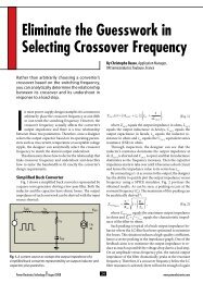
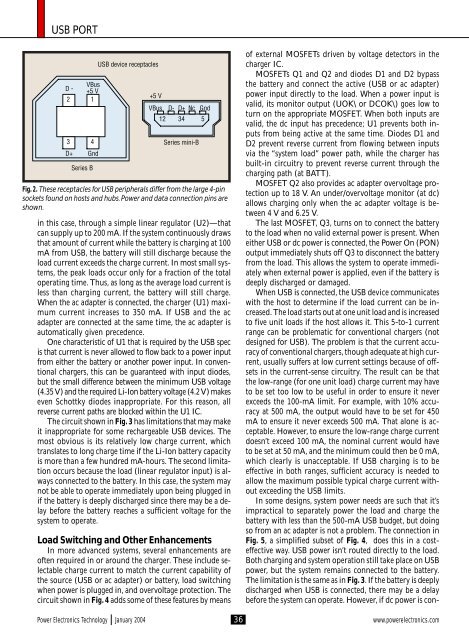
Fig. 2. These receptacles for <strong>USB</strong> peripherals differ from the large 4-pin<br />
sockets found on hosts and hubs. <strong>Power</strong> and data connection pins are<br />
shown.<br />
in this case, through a simple linear regulator (U2)—that<br />
can supply up to 200 mA. If the system continuously draws<br />
that amount of current while the battery is charging at 100<br />
mA from <strong>USB</strong>, the battery will still discharge because the<br />
load current exceeds the charge current. In most small systems,<br />
the peak loads occur only for a fraction of the total<br />
operating time. Thus, as long as the average load current is<br />
less than charging current, the battery will still charge.<br />
When the ac adapter is connected, the charger (U1) maximum<br />
current increases to 350 mA. If <strong>USB</strong> and the ac<br />
adapter are connected at the same time, the ac adapter is<br />
automatically given precedence.<br />
One characteristic of U1 that is required by the <strong>USB</strong> spec<br />
is that current is never allowed to flow back to a power input<br />
from either the battery or another power input. In conventional<br />
chargers, this can be guaranteed with input diodes,<br />
but the small difference between the minimum <strong>USB</strong> voltage<br />
(4.35 V) and the required Li-Ion battery voltage (4.2 V) makes<br />
even Schottky diodes inappropriate. For this reason, all<br />
reverse current paths are blocked within the U1 IC.<br />
The circuit shown in Fig. 3 has limitations that may make<br />
it inappropriate for some rechargeable <strong>USB</strong> devices. The<br />
most obvious is its relatively low charge current, which<br />
translates to long charge time if the Li-Ion battery capacity<br />
is more than a few hundred mA-hours. The second limitation<br />
occurs because the load (linear regulator input) is always<br />
connected to the battery. In this case, the system may<br />
not be able to operate immediately upon being plugged in<br />
if the battery is deeply discharged since there may be a delay<br />
before the battery reaches a sufficient voltage for the<br />
system to operate.<br />
Load Switching and Other Enhancements<br />
In more advanced systems, several enhancements are<br />
often required in or around the charger. These include selectable<br />
charge current to match the current capability of<br />
the source (<strong>USB</strong> or ac adapter) or battery, load switching<br />
when power is plugged in, and overvoltage protection. The<br />
circuit shown in Fig. 4 adds some of these features by means<br />
of external MOSFETs driven by voltage detectors in the<br />
charger IC.<br />
MOSFETs Q1 and Q2 and diodes D1 and D2 bypass<br />
the battery and connect the active (<strong>USB</strong> or ac adapter)<br />
power input directly to the load. When a power input is<br />
valid, its monitor output (UOK\ or DCOK\) goes low to<br />
turn on the appropriate MOSFET. When both inputs are<br />
valid, the dc input has precedence; U1 prevents both inputs<br />
from being active at the same time. Diodes D1 and<br />
D2 prevent reverse current from flowing between inputs<br />
via the “system load” power path, while the charger has<br />
built-in circuitry to prevent reverse current through the<br />
charging path (at BATT).<br />
MOSFET Q2 also provides ac adapter overvoltage protection<br />
up to 18 V. An under/overvoltage monitor (at dc)<br />
allows charging only when the ac adapter voltage is between<br />
4 V and 6.25 V.<br />
The last MOSFET, Q3, turns on to connect the battery<br />
to the load when no valid external power is present. When<br />
either <strong>USB</strong> or dc power is connected, the <strong>Power</strong> On (PON)<br />
output immediately shuts off Q3 to disconnect the battery<br />
from the load. This allows the system to operate immediately<br />
when external power is applied, even if the battery is<br />
deeply discharged or damaged.<br />
When <strong>USB</strong> is connected, the <strong>USB</strong> device communicates<br />
with the host to determine if the load current can be increased.<br />
The load starts out at one unit load and is increased<br />
to five unit loads if the host allows it. This 5-to-1 current<br />
range can be problematic for conventional chargers (not<br />
designed for <strong>USB</strong>). The problem is that the current accuracy<br />
of conventional chargers, though adequate at high current,<br />
usually suffers at low current settings because of offsets<br />
in the current-sense circuitry. The result can be that<br />
the low-range (for one unit load) charge current may have<br />
to be set too low to be useful in order to ensure it never<br />
exceeds the 100-mA limit. For example, with 10% accuracy<br />
at 500 mA, the output would have to be set for 450<br />
mA to ensure it never exceeds 500 mA. That alone is acceptable.<br />
However, to ensure the low-range charge current<br />
doesn’t exceed 100 mA, the nominal current would have<br />
to be set at 50 mA, and the minimum could then be 0 mA,<br />
which clearly is unacceptable. If <strong>USB</strong> charging is to be<br />
effective in both ranges, sufficient accuracy is needed to<br />
allow the maximum possible typical charge current without<br />
exceeding the <strong>USB</strong> limits.<br />
In some designs, system power needs are such that it’s<br />
impractical to separately power the load and charge the<br />
battery with less than the 500-mA <strong>USB</strong> budget, but doing<br />
so from an ac adapter is not a problem. The connection in<br />
Fig. 5, a simplified subset of Fig. 4, does this in a costeffective<br />
way. <strong>USB</strong> power isn’t routed directly to the load.<br />
Both charging and system operation still take place on <strong>USB</strong><br />
power, but the system remains connected to the battery.<br />
The limitation is the same as in Fig. 3. If the battery is deeply<br />
discharged when <strong>USB</strong> is connected, there may be a delay<br />
before the system can operate. However, if dc power is con-<br />
<strong>Power</strong> <strong>Electronics</strong> Technology January 2004 36<br />
www.powerelectronics.com