Power Electronics Technology
Power Electronics Technology
Power Electronics Technology

Create successful ePaper yourself
Turn your PDF publications into a flip-book with our unique Google optimized e-Paper software.
THERMALmanagement<br />
els the temperature increase<br />
becomes a factor in determining<br />
ampacity because the<br />
resistivity of the conductor<br />
changes with temperature.<br />
The relationship is linear, i.e.,<br />
resistivity increases proportional to the change in temperature<br />
at a rate determined by the temperature coefficient of<br />
the conductor:<br />
R T = R T0 × [(1 + (T - T 0 )] (1)<br />
Where:<br />
T = Temperature at which resistivity is measured<br />
T 0 = Reference temperature (ambient)<br />
= Linear temperature coefficient (copper = 0.004)<br />
R T = Resistivity at measurement temperature<br />
R T0 = Resistivity at reference temperature<br />
For a copper conductor, every 25°C increase in temperature<br />
means a drop of about 5% in maximum ampacity<br />
due to an increase in conductor resistivity, RT . Since<br />
this presents the probability of further power dissipation<br />
and temperature rise, MiB design practice must consider<br />
effective methods not only to control and reduce conductor<br />
resistivity, but also to provide low thermal resistance<br />
pathways for heat dissipation.<br />
In a printed circuit board, ampacity depends on a number<br />
of different factors:<br />
• Conductive + convective capability provided by spreading<br />
layers, ground layers, stack-up<br />
• Ratio of track width to thickness<br />
• Ambient temperature<br />
• Adjacent high current tracks<br />
• AC or DC current<br />
• Presence and frequency of partial crosssection<br />
shrinkage<br />
• Presence, number, and conductive<br />
cross-section of plated through holes in<br />
series with the conductor.<br />
Therefore effective design needs to<br />
consider more variables than are normally<br />
addressed by the IPC-2152 current vs.<br />
temperature charts.<br />
MIB<br />
“Metal in the Board” or “MiB” includes<br />
a number of approaches where MiB<br />
building blocks are combined to provide<br />
effective high-current solutions.<br />
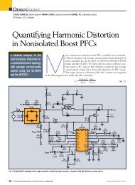
The “DWPCB” (discrete wire PCB) type<br />
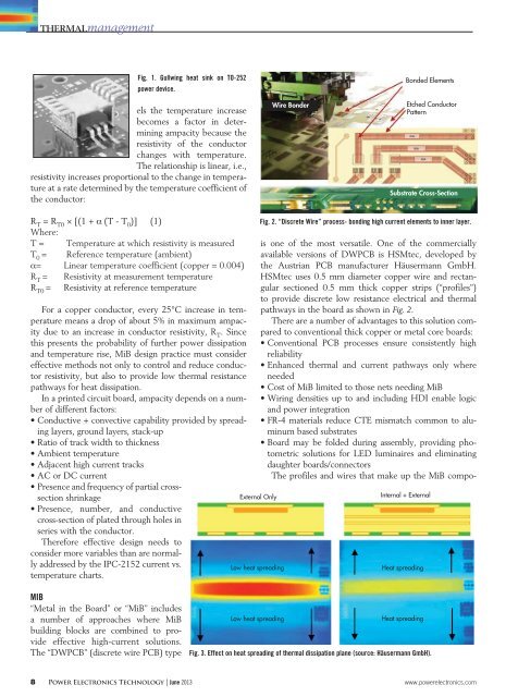
Fig. 1. Gullwing heat sink on TO-252<br />
power device.<br />
External Only<br />
Low heat spreading<br />
Low heat spreading<br />
Wire Bonder<br />
Bonded Elements<br />
Etched Conductor<br />
Pattern<br />
Substrate Cross-Section<br />
Fig. 2. “Discrete Wire” process- bonding high current elements to inner layer.<br />
is one of the most versatile. One of the commercially<br />
available versions of DWPCB is HSMtec, developed by<br />
the Austrian PCB manufacturer Häusermann GmbH.<br />
HSMtec uses 0.5 mm diameter copper wire and rectangular<br />
sectioned 0.5 mm thick copper strips (“profiles”)<br />
to provide discrete low resistance electrical and thermal<br />
pathways in the board as shown in Fig. 2.<br />
There are a number of advantages to this solution compared<br />
to conventional thick copper or metal core boards:<br />
• Conventional PCB processes ensure consistently high<br />
reliability<br />
• Enhanced thermal and current pathways only where<br />
needed<br />
• Cost of MiB limited to those nets needing MiB<br />
• Wiring densities up to and including HDI enable logic<br />
and power integration<br />
• FR-4 materials reduce CTE mismatch common to aluminum<br />
based substrates<br />
• Board may be folded during assembly, providing photometric<br />
solutions for LED luminaires and eliminating<br />
daughter boards/connectors<br />
The profiles and wires that make up the MiB compo-<br />
Internal + External<br />
Heat spreading<br />
Heat spreading<br />
Fig. 3. Effect on heat spreading of thermal dissipation plane (source: Häusermann GmbH).<br />
8 <strong>Power</strong> <strong>Electronics</strong> <strong>Technology</strong> | June 2013 www.powerelectronics.com