A continuous damped vibration absorber to reduce broad-band ...
A continuous damped vibration absorber to reduce broad-band ...
A continuous damped vibration absorber to reduce broad-band ...

You also want an ePaper? Increase the reach of your titles
YUMPU automatically turns print PDFs into web optimized ePapers that Google loves.
Damping can be added as before by making s1 and s2 complex with loss fac<strong>to</strong>rs Z1 and Z2, respectively. If the<br />
beam is constrained, the mass ms 0 can vibrate freely on the combined stiffness of the two layers at the<br />
frequency oa, given by<br />
rffiffiffiffiffiffiffiffiffiffiffiffiffiffi<br />
s1 þ s2<br />
oa ¼ . (40)<br />
This corresponds <strong>to</strong> an anti-resonance of the support as seen at the beam and is the tuning frequency of the<br />
two-layer support at which it acts as a neutraliser <strong>to</strong> the beam.<br />
0 2<br />
There are two frequencies at which mr o s(o) ¼ 0, corresponding <strong>to</strong> the condition of cut-off seen<br />
in Section 3. These are the natural frequencies of the corresponding two-degree-of-freedom system shown in<br />
Fig. 10(b). They can be found as<br />
o 2 c ¼ ðo21 þ o2a Þ<br />
ffiffiffiffiffiffiffiffiffiffiffiffiffiffiffiffiffiffiffiffiffiffiffiffiffiffiffiffiffiffiffiffiffiffiffiffiffiffi<br />
ðo<br />
2<br />
2 1 þ o2a Þ2<br />
o<br />
4<br />
2 1o2 s<br />
2,<br />
(41a)<br />
where o1 and o2 are given by<br />
ARTICLE IN PRESS<br />
o1 ¼<br />
m 0 s<br />
rffiffiffiffiffiffi<br />
rffiffiffiffiffiffi<br />
s1<br />
s2<br />
; o2 ¼ . (41b,c)<br />
m 0 r<br />
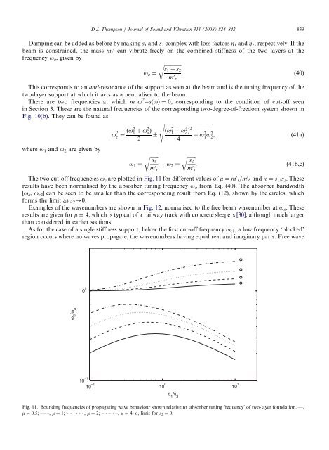
The two cut-off frequencies o c are plotted in Fig. 11 for different values of m ¼ m 0 s=m 0 b and k ¼ s 1/s 2. These<br />
results have been normalised by the <strong>absorber</strong> tuning frequency o a from Eq. (40). The <strong>absorber</strong> <strong>band</strong>width<br />
[oa, oc2] can be seen <strong>to</strong> be smaller than the corresponding result from Eq. (12), shown by the circles, which<br />
forms the limit as s2-0.<br />
Examples of the wavenumbers are shown in Fig. 12, normalised <strong>to</strong> the free beam wavenumber at oa. These<br />
results are given for m ¼ 4, which is typical of a railway track with concrete sleepers [30], although much larger<br />
than considered in earlier sections.<br />
As for the case of a single stiffness support, below the first cut-off frequency oc1, a low frequency ‘blocked’<br />
region occurs where no waves propagate, the wavenumbers having equal real and imaginary parts. Free wave<br />
ω 0 /ω a<br />
10 0<br />
D.J. Thompson / Journal of Sound and Vibration 311 (2008) 824–842 839<br />
10 10 0<br />
10<br />
Fig. 11. Bounding frequencies of propagating wave behaviour shown relative <strong>to</strong> ‘<strong>absorber</strong> tuning frequency’ of two-layer foundation. —,<br />
m ¼ 0.5; – – –, m ¼ 1; , m ¼ 2; – – –, m ¼ 4; o, limit for s2 ¼ 0.<br />
s 1 /s 2<br />
m 0 s<br />
10 1