- Page 1: System Manual Edition 03/2007 siriu
- Page 4 and 5: Safety Information This manual cont
- Page 6 and 7: Table Of Contents 4 Motor Control .
- Page 8 and 9: Table Of Contents 12 Communication
- Page 10 and 11: Table Of Contents B.20.3 Reversing
- Page 12 and 13: Table Of Contents E.9.2 "Dahlander
- Page 14 and 15: Table Of Contents SIMOCODE pro x GW
- Page 16 and 17: Important Information Scope of Appl
- Page 18 and 19: Important Information SIMOCODE pro
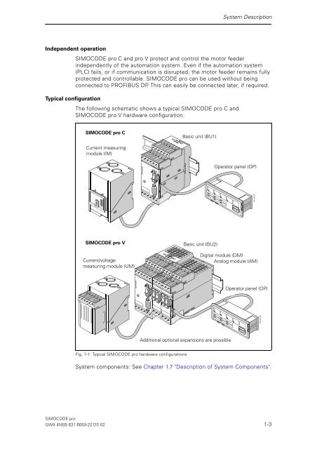
- Page 22 and 23: System Description 1.2 Simplifying
- Page 24 and 25: System Description 1.3 Application
- Page 26 and 27: System Description 1.4 Check List f
- Page 28 and 29: System Description 1.5 Overview of
- Page 30 and 31: System Description Monitoring opera
- Page 32 and 33: System Description 1.5.4 Communicat
- Page 34 and 35: System Description 1.5.7 Operating,
- Page 36 and 37: System Description 1.6 Overview of
- Page 38 and 39: System Description Accessories For
- Page 40 and 41: System Description 1.7 Description
- Page 42 and 43: System Description 1.7.2 Operator P
- Page 44 and 45: System Description Unused labeling
- Page 46 and 47: System Description The operator pan
- Page 48 and 49: System Description Displays of the
- Page 50 and 51: System Description Menu of the oper
- Page 52 and 53: System Description Warnings The "Wa
- Page 54 and 55: System Description Imax [%] (exampl
- Page 56 and 57: System Description Temperatures °F
- Page 58 and 59: System Description Display of measu
- Page 60 and 61: System Description Time to Trip Dis
- Page 62 and 63: System Description Interlocking Tim
- Page 64 and 65: System Description Display of stati
- Page 66 and 67: System Description Number of Parame
- Page 68 and 69: System Description Status display f
- Page 70 and 71:
System Description 3UF50 Basic Type
- Page 72 and 73:
System Description Current Measurin
- Page 74 and 75:
System Description Sensor Type Pt10
- Page 76 and 77:
System Description Profiles See Sec
- Page 78 and 79:
System Description Resetting, testi
- Page 80 and 81:
System Description Display of all p
- Page 82 and 83:
System Description Basic Unit MLFB
- Page 84 and 85:
System Description Timestamp (examp
- Page 86 and 87:
System Description 1.7.5 Current/Vo
- Page 88 and 89:
System Description 1.7.6 Decoupling
- Page 90 and 91:
System Description Digital module (
- Page 92 and 93:
System Description Earth-fault modu
- Page 94 and 95:
System Description 1.7.8 Configurat
- Page 96 and 97:
System Description 1.7.9 Accessorie
- Page 98 and 99:
System Description 1.7.10 Software
- Page 100 and 101:
System Description 1.8 Structural C
- Page 102 and 103:
System Description Connecting plugs
- Page 104 and 105:
System Description Acyclic Send Byt
- Page 106 and 107:
System Description Calculator (Calc
- Page 108 and 109:
System Description Extended Control
- Page 110 and 111:
System Description Non-Volatile Ele
- Page 112 and 113:
System Description Current Limits F
- Page 114 and 115:
System Description Monitoring 0/4 -
- Page 116 and 117:
System Description Temperature Moni
- Page 118 and 119:
System Description Watchdog Fig. 1-
- Page 120 and 121:
System Description SIMOCODE pro 1-1
- Page 122 and 123:
Short Instructions for Configuring
- Page 124 and 125:
Short Instructions for Configuring
- Page 126 and 127:
Short Instructions for Configuring
- Page 128 and 129:
Short Instructions for Configuring
- Page 130 and 131:
Short Instructions for Configuring
- Page 132 and 133:
Short Instructions for Configuring
- Page 134 and 135:
Motor Protection 3.1 Introduction D
- Page 136 and 137:
Motor Protection Adjustable respons
- Page 138 and 139:
Motor Protection Is1 Transformation
- Page 140 and 141:
Motor Protection Class The class (t
- Page 142 and 143:
Motor Protection Response to Overlo
- Page 144 and 145:
Motor Protection Pre-alarm Delay Re
- Page 146 and 147:
Motor Protection 3.4 Stalled Rotor
- Page 148 and 149:
Motor Protection Sensor Fault (Sens
- Page 150 and 151:
Motor Control 4.1 Control Stations
- Page 152 and 153:
Motor Control Control Station - PC
- Page 154 and 155:
Motor Control Operating Mode Select
- Page 156 and 157:
Motor Control Example for operator
- Page 158 and 159:
Motor Control 4.2 Control Functions
- Page 160 and 161:
Motor Control General representatio
- Page 162 and 163:
Motor Control Extent and applicatio
- Page 164 and 165:
Motor Control Parameters Parameters
- Page 166 and 167:
Motor Control Faults Parameters Des
- Page 168 and 169:
Motor Control 4.2.4 "Direct Starter
- Page 170 and 171:
Motor Control 4.2.5 "Reversing Star
- Page 172 and 173:
Motor Control Settings You will fin
- Page 174 and 175:
Motor Control Schematic Settings Fi
- Page 176 and 177:
Motor Control Change-over Pause Sch
- Page 178 and 179:
Motor Control 4.2.8 "Star-Delta Rev
- Page 180 and 181:
Motor Control Schematic Control Com
- Page 182 and 183:
Motor Control 4.2.9 "Dahlander" Con
- Page 184 and 185:
Motor Control Settings You will fin
- Page 186 and 187:
Motor Control Change-over Pause Saf
- Page 188 and 189:
Motor Control Settings You will fin
- Page 190 and 191:
Motor Control Schematic Settings Fi
- Page 192 and 193:
Motor Control 4.2.12 "Pole-Changing
- Page 194 and 195:
Motor Control Schematic Control Com
- Page 196 and 197:
Motor Control 4.2.13 "Solenoid Valv
- Page 198 and 199:
Motor Control 4.2.14 "Positioner" C
- Page 200 and 201:
Motor Control Schematic * Abbreviat
- Page 202 and 203:
Motor Control Settings You will fin
- Page 204 and 205:
Motor Control Schematic Settings Fi
- Page 206 and 207:
Motor Control Making internal assig
- Page 208 and 209:
Motor Control 4.3 Active Control St
- Page 210 and 211:
Monitoring Functions 5.1 Earth-Faul
- Page 212 and 213:
Monitoring Functions 5.1.3 External
- Page 214 and 215:
Monitoring Functions 5.2.2 I> (Uppe
- Page 216 and 217:
Monitoring Functions 5.3 Voltage Mo
- Page 218 and 219:
Monitoring Functions 5.4 Cos Phi Mo
- Page 220 and 221:
Monitoring Functions 5.5 Active Pow
- Page 222 and 223:
Monitoring Functions 5.6 Monitoring
- Page 224 and 225:
Monitoring Functions Response when
- Page 226 and 227:
Monitoring Functions Response Table
- Page 228 and 229:
Monitoring Functions Response at Pr
- Page 230 and 231:
Monitoring Functions Trip Level and
- Page 232 and 233:
Monitoring Functions SIMOCODE pro 5
- Page 234 and 235:
Outputs 6.1 Introduction Descriptio
- Page 236 and 237:
Outputs 6.2 Basic Unit Outputs Desc
- Page 238 and 239:
Outputs 6.3 Operator Panel LEDs Des
- Page 240 and 241:
Outputs Application examples Settin
- Page 242 and 243:
Outputs Settings In many cases, the
- Page 244 and 245:
Outputs Note The Outputs of the ana
- Page 246 and 247:
Outputs 2) Output of the Effective
- Page 248 and 249:
Outputs 6.6 Cyclic Send Description
- Page 250 and 251:
Outputs 6.7 Acyclic Send Descriptio
- Page 252 and 253:
Inputs 7.1 Introduction Description
- Page 254 and 255:
Inputs 7.2 Basic Unit Inputs Descri
- Page 256 and 257:
Inputs 7.3 Operator Panel Buttons D
- Page 258 and 259:
Inputs Schematic The following sche
- Page 260 and 261:
Inputs Application examples Supplyi
- Page 262 and 263:
Inputs Application examples Setting
- Page 264 and 265:
Inputs Application examples Setting
- Page 266 and 267:
Inputs 7.8 Acyclic Receive Descript
- Page 268 and 269:
Analog Value Recording Description
- Page 270 and 271:
Analog Value Recording SIMOCODE pro
- Page 272 and 273:
3UF50 Compatibility Mode Descriptio
- Page 274 and 275:
3UF50 Compatibility Mode Diagram of
- Page 276 and 277:
3UF50 Compatibility Mode Byte Bit 1
- Page 278 and 279:
Standard Functions 10.1 Introductio
- Page 280 and 281:
Standard Functions Testing Reset Fu
- Page 282 and 283:
Standard Functions Acknowledgement
- Page 284 and 285:
Standard Functions Cold Starting If
- Page 286 and 287:
Standard Functions Special reset op
- Page 288 and 289:
Standard Functions Settings Operati
- Page 290 and 291:
Standard Functions 10.6 Power Failu
- Page 292 and 293:
Standard Functions 10.7 Emergency S
- Page 294 and 295:
Standard Functions Settings Watchdo
- Page 296 and 297:
Standard Functions Schematic Settin
- Page 298 and 299:
Logic Modules 11.1 Introduction Des
- Page 300 and 301:
Logic Modules Example You want to i
- Page 302 and 303:
Logic Modules 11.3 Truth Table for
- Page 304 and 305:
Logic Modules 11.5 Counters Descrip
- Page 306 and 307:
Logic Modules 11.6 Timer Descriptio
- Page 308 and 309:
Logic Modules Output Response of th
- Page 310 and 311:
Logic Modules Settings Timers 1 to
- Page 312 and 313:
Logic Modules Types of Signals/Outp
- Page 314 and 315:
Logic Modules 11.8 Non-Volatile Ele
- Page 316 and 317:
Logic Modules NOR function Settings
- Page 318 and 319:
Logic Modules 11.10 Flickering Desc
- Page 320 and 321:
Logic Modules Functional principle
- Page 322 and 323:
Logic Modules Examples of typical u
- Page 324 and 325:
Logic Modules Operating Modes for C
- Page 326 and 327:
Logic Modules Examples Example 1 Ex
- Page 328 and 329:
Communication 12.1 Definitions PROF
- Page 330 and 331:
Communication 12.2 Data Transfer Op
- Page 332 and 333:
Communication 12.3.2 Diagnosis Data
- Page 334 and 335:
Communication Station Status - Defi
- Page 336 and 337:
Communication Identification-relate
- Page 338 and 339:
Communication Channel-related Diagn
- Page 340 and 341:
Communication Alarms - Process Alar
- Page 342 and 343:
Communication 12.4.3 Integration of
- Page 344 and 345:
Communication 12.4.5 Integration of
- Page 346 and 347:
Communication of the device are tra
- Page 348 and 349:
Communication 12.6 Data Records Dat
- Page 350 and 351:
Communication 12.7.3 Parameter Data
- Page 352 and 353:
Mounting, Wiring, Interfaces 13.1 G
- Page 354 and 355:
Mounting, Wiring, Interfaces 13.2.2
- Page 356 and 357:
Mounting, Wiring, Interfaces 13.2.4
- Page 358 and 359:
Mounting, Wiring, Interfaces 13.2.5
- Page 360 and 361:
Mounting, Wiring, Interfaces 13.3 W
- Page 362 and 363:
Mounting, Wiring, Interfaces Basic
- Page 364 and 365:
Mounting, Wiring, Interfaces Supply
- Page 366 and 367:
Mounting, Wiring, Interfaces Earth-
- Page 368 and 369:
Mounting, Wiring, Interfaces Temper
- Page 370 and 371:
Mounting, Wiring, Interfaces Analog
- Page 372 and 373:
Mounting, Wiring, Interfaces Decoup
- Page 374 and 375:
Mounting, Wiring, Interfaces 13.3.3
- Page 376 and 377:
Mounting, Wiring, Interfaces 13.3.4
- Page 378 and 379:
Mounting, Wiring, Interfaces Exampl
- Page 380 and 381:
Mounting, Wiring, Interfaces Fig. 1
- Page 382 and 383:
Mounting, Wiring, Interfaces 13.4.2
- Page 384 and 385:
Mounting, Wiring, Interfaces Notice
- Page 386 and 387:
Mounting, Wiring, Interfaces Sequen
- Page 388 and 389:
Mounting, Wiring, Interfaces Front
- Page 390 and 391:
Mounting, Wiring, Interfaces 13.6 I
- Page 392 and 393:
Commissioning and Service 14.1 Gene
- Page 394 and 395:
Commissioning and Service 14.2.2 Se
- Page 396 and 397:
Commissioning and Service 14.3 Serv
- Page 398 and 399:
Commissioning and Service Saving pa
- Page 400 and 401:
Commissioning and Service Replacing
- Page 402 and 403:
Commissioning and Service 14.3.4 Re
- Page 404 and 405:
Commissioning and Service Example:
- Page 406 and 407:
Alarm, Fault and System Events Even
- Page 408 and 409:
Alarm, Fault and System Events Even
- Page 410 and 411:
Alarm, Fault and System Events Even
- Page 412 and 413:
Alarm, Fault and System Events Even
- Page 414 and 415:
Tables A.1 Active Control Stations,
- Page 416 and 417:
Tables Specifications The following
- Page 418 and 419:
Tables No. Designation Designation
- Page 420 and 421:
Tables No. Designation Designation
- Page 422 and 423:
Tables No. Designation Designation
- Page 424 and 425:
Tables A.4 Socket Assignment Table
- Page 426 and 427:
Tables A.5 Detailed Events of the S
- Page 428 and 429:
Tables Byte.Bit Status Information
- Page 430 and 431:
Data Formats and Data Records Data
- Page 432 and 433:
Data Formats and Data Records B.1.2
- Page 434 and 435:
Data Formats and Data Records Byte
- Page 436 and 437:
Data Formats and Data Records B.5 D
- Page 438 and 439:
Data Formats and Data Records B.7 D
- Page 440 and 441:
Data Formats and Data Records Byte.
- Page 442 and 443:
Data Formats and Data Records Byte.
- Page 444 and 445:
Data Formats and Data Records B.8 D
- Page 446 and 447:
Data Formats and Data Records B.10
- Page 448 and 449:
Data Formats and Data Records Byte
- Page 450 and 451:
Data Formats and Data Records Byte
- Page 452 and 453:
Data Formats and Data Records Byte.
- Page 454 and 455:
Data Formats and Data Records Byte.
- Page 456 and 457:
Data Formats and Data Records Byte.
- Page 458 and 459:
Data Formats and Data Records Byte.
- Page 460 and 461:
Data Formats and Data Records Byte.
- Page 462 and 463:
Data Formats and Data Records Byte.
- Page 464 and 465:
Data Formats and Data Records B.14
- Page 466 and 467:
Data Formats and Data Records B.17
- Page 468 and 469:
Data Formats and Data Records B.19
- Page 470 and 471:
Data Formats and Data Records B.20.
- Page 472 and 473:
Data Formats and Data Records B.20.
- Page 474 and 475:
Data Formats and Data Records B.20.
- Page 476 and 477:
Data Formats and Data Records B.20.
- Page 478 and 479:
Data Formats and Data Records B.20.
- Page 480 and 481:
Data Formats and Data Records B.20.
- Page 482 and 483:
Data Formats and Data Records B.20.
- Page 484 and 485:
Dimension Drawings C.1 3UF70 Basic
- Page 486 and 487:
Dimension Drawings C.2.2 Current Me
- Page 488 and 489:
Dimension Drawings C.2.4 Current Me
- Page 490 and 491:
Dimension Drawings C.3 Current/Volt
- Page 492 and 493:
Dimension Drawings C.3.3 Current/Vo
- Page 494 and 495:
Dimension Drawings C.3.5 Current/Vo
- Page 496 and 497:
Dimension Drawings C.5 Expansion Mo
- Page 498 and 499:
Dimension Drawings SIMOCODE pro C-1
- Page 500 and 501:
Technical Data D.1 Common Technical
- Page 502 and 503:
Technical Data Relay Outputs: Numbe
- Page 504 and 505:
Technical Data Notes on voltage mea
- Page 506 and 507:
Technical Data D.5 Technical Data o
- Page 508 and 509:
Technical Data D.5.3 Technical Data
- Page 510 and 511:
Technical Data D.6 Technical Data o
- Page 512 and 513:
Technical Data D.7 Short-Circuit Pr
- Page 514 and 515:
Technical Data SIMOCODE pro D-16 GW
- Page 516 and 517:
Example Circuits E.1 General Object
- Page 518 and 519:
Example Circuits E.2.1 "Overload Re
- Page 520 and 521:
Example Circuits E.3 "Direct Starte
- Page 522 and 523:
Example Circuits E.4 "Reversing Sta
- Page 524 and 525:
Example Circuits E.5 "Molded Case C
- Page 526 and 527:
Example Circuits E.6 "Star-Delta St
- Page 528 and 529:
Example Circuits E.6.3 "Star-Delta
- Page 530 and 531:
Example Circuits E.7 "Star-Delta Re
- Page 532 and 533:
Example Circuits E.8 "Dahlander" Ci
- Page 534 and 535:
Example Circuits E.9 "Dahlander Rev
- Page 536 and 537:
Example Circuits Fig. E-19: "Dahlan
- Page 538 and 539:
Example Circuits E.10.1 "Pole-Chang
- Page 540 and 541:
Example Circuits E.11 "Pole-Changin
- Page 542 and 543:
Example Circuits Fig. E-24: "Pole-C
- Page 544 and 545:
Example Circuits E.12.1 "Solenoid V
- Page 546 and 547:
Example Circuits E.13 "Positioner"
- Page 548 and 549:
Example Circuits E.13.3 "Positioner
- Page 550 and 551:
Example Circuits E.13.5 "Positioner
- Page 552 and 553:
Example Circuits E.13.7 "Positioner
- Page 554 and 555:
Example Circuits E.13.9 "Positioner
- Page 556 and 557:
Example Circuits E.14 "Soft Starter
- Page 558 and 559:
Example Circuits E.14.2 "Soft Start
- Page 560 and 561:
Example Circuits E.15.1 "Soft Start
- Page 562 and 563:
Example Circuits E.15.2 "Soft Start
- Page 564 and 565:
Example Circuits E.16.1 Direct Star
- Page 566 and 567:
Example Circuits E.16.2 Direct Star
- Page 568 and 569:
Example Circuits E.16.3 Reversing S
- Page 570 and 571:
Example Circuits E.16.4 Reversing S
- Page 572 and 573:
Example Circuits E.16.5 Star-Delta
- Page 574 and 575:
Example Circuits E.16.6 Pole-Changi
- Page 576 and 577:
Example Circuits E.16.7 Pole-Changi
- Page 578 and 579:
Example Circuits E.16.8 Dahlander,
- Page 580 and 581:
Example Circuits SIMOCODE pro E-66
- Page 582 and 583:
Safety and Commissioning Informatio
- Page 584 and 585:
Safety and Commissioning Informatio
- Page 586 and 587:
Safety and Commissioning Informatio
- Page 588 and 589:
Safety and Commissioning Informatio
- Page 590 and 591:
Safety and Commissioning Informatio
- Page 592 and 593:
Index Binary inputs for 110... 240
- Page 594 and 595:
Index Data record 92 - device diagn
- Page 596 and 597:
Index I I max 1-40 I> (upper limit)
- Page 598 and 599:
Index Open circuit 1-55 Operating d
- Page 600 and 601:
Index Replacing an expansion module
- Page 602 and 603:
Index Standard diagnosis 12-6, 12-1
- Page 604 and 605:
Index works) in connection with an
- Page 606 and 607:
List of Abbreviations SIMOCODE pro
- Page 608 and 609:
Glossary Baud Rate Bus Bus Segment
- Page 610 and 611:
Glossary Current Measuring Module (
- Page 612 and 613:
Glossary Factory Settings Function
- Page 614 and 615:
Glossary Monitoring the Current Lim
- Page 616 and 617:
Glossary PROFIBUS PROFIBUS DP PROFI
- Page 618 and 619:
Glossary Standard Function Station
- Page 620 and 621:
Glossary SIMOCODE pro Glossary-14 G
- Page 624:
Siemens Aktiengesellschaft Automati