


Create successful ePaper yourself
Turn your PDF publications into a flip-book with our unique Google optimized e-Paper software.
2<br />
Squirrel-cage motors<br />
Technical information<br />
Mechanical design<br />
■ Maximum cantilever forces<br />
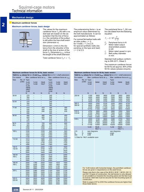
Maximum cantilever forces, basic design<br />
The values for the maximum<br />
cantilever force FQ (N) with a radial<br />
load are based on the assumption<br />
that the line of force<br />
FQ (i.e. the centreline of the pulley)<br />
is still within the free shaft extension<br />
(dimension x).<br />
x<br />
M1-5180<br />
Dimension x (mm) is the distance<br />
from the shoulder of the<br />
shaft to the line of action of the<br />
force FQ. Dimension xmax. is thus<br />
the length of the shaft extension.<br />
Total cantilever force FQ = c · Fu 2/36<br />
Siemens M 11 · 2003/2004<br />
The pretensioning factor c is an<br />
empirical value determined by<br />
the belt manufacturer. It can be<br />
approximated as fol<strong>low</strong>s:<br />
For normal flat leather belts with<br />
an idler pulley c = 2;<br />
for V-belts c = 2 to 2.5;<br />
for special synthetic belts (depending<br />
on the type and load)<br />
c = 2 to 2.5.<br />
The peripheral force Fu (N) can<br />
be calculated from the fol<strong>low</strong>ing<br />
equation<br />
7 P<br />
Fu<br />
2¸10 n¸D F u<br />
Peripheral force in N<br />
P Motor rated output<br />
(transmitted power)<br />
in kW<br />
n Motor rated speed in rpm<br />
D Belt pulley diameter<br />
in mm<br />
Standard belt pulleys conforming<br />
to DIN 2211, Sheet 3.<br />
The maximum cantilever forces<br />
for 60 Hz are approx. 80% of the<br />
50 Hz values (please enquire).<br />
Maximum cantilever forces for 50 Hz, basic version<br />
Maximum cantilever forces for 50 Hz, basic version<br />
Valid is: x0 values for x = 0 and xmax. values for x = l (l = shaft extension) Valid is: x0 values for x = 0 and xmax. values for x = l (l = shaft extension)<br />
For motors Max. cantilever force at x0 Max. cantilever force at xmax. For motors Max. cantilever force at x0 Max. cantilever force at xmax. Size No. of Type Type<br />
Size No. of Type Type<br />
poles 1LA5 1LG4 1MJ6 1LA5 1LG4 1MJ6<br />
poles 1LG4 1MA6 1MJ6 1LG4 1MA6 1MJ6<br />
1LA7 1LG6 1MJ7 1LA7 1LG6 1MJ7<br />
1LG6<br />
1MJ7 1LG6<br />
1MJ7<br />
1LA9<br />
1LA9<br />
1MA6<br />
1MA6<br />
1MA7<br />
1MA7<br />
1LA6<br />
1LA6<br />
N N N N N N<br />
N N N N N N<br />
56 M 2 270 – – 240 – –<br />
250 M 2 3190 3650 3650 2530 2950 2950<br />
4 350 – – 305 – –<br />
4 4000 4400 4400 3350 3600 3600<br />
6 415 – – 360 – –<br />
6 4700 5350 5350 3900 4350 4350<br />
63 M 2 270 – – 240 – –<br />
8 5200 5700 5700 4400 4700 4700<br />
4 350 – – 305 – –<br />
280 S 2 4000 3350 8100 3250 2800 6700<br />
6 415 – – 360 – –<br />
280 M 4 8400 8400 9700 7000 7200 8050<br />
71 M 2<br />
4<br />
415<br />
530<br />
–<br />
–<br />
415<br />
530<br />
355<br />
450<br />
–<br />
–<br />
355<br />
450<br />
6<br />
8<br />
9700<br />
10750<br />
10000<br />
11000<br />
11700<br />
12800<br />
8100<br />
9000<br />
8900<br />
9850<br />
9700<br />
10600<br />
6 630 – 630 535 – 535 315 S 2 4750 3950 9000 3890 3350 7600<br />
8 690 – – 585 – –<br />
315 M 4 9100 9900 13100 7300 8100 10800<br />
80 M 2<br />
4<br />
485<br />
625<br />
–<br />
–<br />
485<br />
625<br />
400<br />
515<br />
–<br />
–<br />
400<br />
515<br />
6<br />
8<br />
10700<br />
11600<br />
12100<br />
13300<br />
15600<br />
16900<br />
8700<br />
9600<br />
9900<br />
10900<br />
12800<br />
13900<br />
6 735 – 735 605 – 605 315 L 2 4000 3100 8800 3280 2700 7600<br />
8 815 – – 675 – 675<br />
4 8400 8800 24000 7500 7450 12000<br />
90 S<br />
90 L<br />
2<br />
4<br />
725<br />
920<br />
–<br />
–<br />
725<br />
920<br />
605<br />
775<br />
–<br />
–<br />
605<br />
775<br />
6<br />
8<br />
9700<br />
11100<br />
11400<br />
12500<br />
25000<br />
26000<br />
9100<br />
10200<br />
9600<br />
10500<br />
12000<br />
12000<br />
6<br />
8<br />
1090<br />
1230<br />
–<br />
–<br />
1090<br />
1230<br />
910<br />
1030<br />
–<br />
–<br />
910<br />
1030<br />
1LA8 1MJ8<br />
1MJ1<br />
100 L 2 1030 – 1030 840 – 840<br />
4 1310 – 1310 1060 – 1060<br />
6 1550 – 1550 1250 – 1250<br />
8 1720 – 1720 1400 – 1400<br />
112 M 2 1010 – 1680 830 – 1490<br />
4 1270 – 1960 1040 – 1580<br />
6 1520 – 2140 1240 – 1720<br />
8 1690 – 2450 1380 – 1950<br />
132 S 2 1490 – 2250 1180 – 1820<br />
132 M 4 1940 – 2720 1530 – 2170<br />
6 2260 – 3100 1780 – 2420<br />
8 2500 – 3400 1980 – 2700<br />
160 M 2 1540 – 2800 1210 – 2250<br />
160 L 4 2040 – 3330 1590 – 2600<br />
6 2330 – 3750 1820 – 2900<br />
8 2660 – 3750 2080 – 2900<br />
180 M 2 2000 1780 2000 1550 1410 1550<br />
180 L 4 2350 2240 2350 1950 1820 1950<br />
200 L<br />
6<br />
8<br />
2<br />
2800<br />
3050<br />
2550<br />
2550<br />
2860<br />
2380<br />
2800<br />
3050<br />
2550<br />
2250<br />
2500<br />
2100<br />
2120<br />
2330<br />
1930<br />
2250<br />
2500<br />
2100<br />
4 3350 3050 3350 2750 2530 2750<br />
6 3900 3500 3900 3200 2930 3200<br />
8 4150 3800 4150 3450 3210 3450<br />
225 S<br />
225 M<br />
2<br />
4<br />
3050<br />
3750<br />
2820<br />
3500<br />
3050<br />
3750<br />
2550<br />
2950<br />
2290<br />
2760<br />
2550<br />
2950<br />
6 4550 4050 4550 3600 3240 3600<br />
8 4850 4500 4850 3900 3500 3900<br />
1 )<br />
1LA8 1MJ8<br />
1MJ1 1 )<br />
315 2 see diagrams<br />
see diagrams<br />
to to page<br />
page<br />
450 8 2/38<br />
2/38<br />
1) Data for 1MJ1 available soon<br />
For 1LA8 motors with horizontal design, the permitted cantilever<br />
forces are given in dependence on the axial forces.<br />
Please note that in the case of the IM B 6, IM B 7, IM B 8, IM V 5,<br />
and IM V 6 types of construction, the belt tension is only al<strong>low</strong>ed<br />
to act parallel to or towards the mounting plane and the feet must<br />
be braced. Both feet must be secured for foot-mounting types of<br />
construction.<br />
Refer to pages 2/37 to 2/39 if the cantilever forces are higher than<br />
those listed above.


