


Create successful ePaper yourself
Turn your PDF publications into a flip-book with our unique Google optimized e-Paper software.
2<br />
Squirrel-cage motors<br />
Technical information<br />
Modular technology<br />
■ Brakes<br />
Spring-operated disk brakes<br />
are used. Depending on the<br />
motor selected, brake types<br />
2LM8 or KFB are used. Standard<br />
brakes are for connection<br />
to 230 V and delivered with a<br />
rectifier.<br />
Order Code G26.<br />
2LM8 spring-operated disk<br />
brake<br />
This brake is fitted to 1LA5 and<br />
1LA7 motors with frame sizes 63<br />
to 225 and to 1LG motors with<br />
frame sizes 180 to 200 as standard.<br />
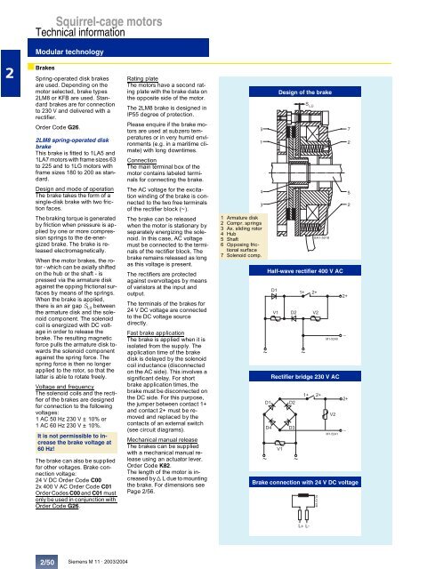
Design and mode of operation<br />
The brake takes the form of a<br />
single-disk brake with two friction<br />
faces.<br />
The braking torque is generated<br />
by friction when pressure is applied<br />
by one or more compression<br />
springs to the de-energized<br />
brake. The brake is released<br />
electromagnetically.<br />
When the motor brakes, the rotor<br />
- which can be axially shifted<br />
on the hub or the shaft - is<br />
pressed via the armature disk<br />
against the opping frictional surfaces<br />
by means of the springs.<br />
When the brake is applied,<br />
there is an air gap SLü between<br />
the armature disk and the solenoid<br />
component. The solenoid<br />
coil is energized with DC <strong>voltage</strong><br />
in order to release the<br />
brake. The resulting magnetic<br />
force pulls the armature disk towards<br />
the solenoid component<br />
against the spring force. The<br />
spring force is then no longer<br />
applied to the rotor, so that the<br />
latter is able to rotate freely.<br />
Voltage and frequency<br />
The solenoid coils and the rectifier<br />
of the brakes are designed<br />
for connection to the fol<strong>low</strong>ing<br />
<strong>voltage</strong>s:<br />
1 AC 50 Hz 230 V ± 10% or<br />
1 AC 60 Hz 230 V ± 10%.<br />
It is not permissible to increase<br />
the brake <strong>voltage</strong> at<br />
60 Hz!<br />
The brake can also be supplied<br />
for other <strong>voltage</strong>s. Brake connection<br />
<strong>voltage</strong>:<br />
24 V DC Order Code C00<br />
2x 400 V AC Order Code C01<br />
Order Codes C00 and C01 must<br />
only be used in conjunction with<br />
Order Code G26.<br />
2/50<br />
Siemens M 11 · 2003/2004<br />
Rating plate<br />
The motors have a second rating<br />
plate with the brake data on<br />
the opposite side of the motor.<br />
The 2LM8 brake is designed in<br />
IP55 degree of protection.<br />
Please enquire if the brake motors<br />
are used at subzero temperatures<br />
or in very humid environments<br />
(e.g. in a maritime climate)<br />
with long downtimes.<br />
Connection<br />
The main terminal box of the<br />
motor contains labeled terminals<br />
for connecting the brake.<br />
The AC <strong>voltage</strong> for the excitation<br />
winding of the brake is connected<br />
to the two free terminals<br />
of the rectifier block (~).<br />
The brake can be released<br />
when the motor is stationary by<br />
separately energizing the solenoid.<br />
In this case, AC <strong>voltage</strong><br />
must be connected to the terminals<br />
of the rectifier block. The<br />
brake remains released as long<br />
as this <strong>voltage</strong> is present.<br />
The rectifiers are protected<br />
against over<strong>voltage</strong>s by means<br />
of varistors at the input and<br />
output.<br />
The terminals of the brakes for<br />
24 V DC <strong>voltage</strong> are connected<br />
to the DC <strong>voltage</strong> source<br />
directly.<br />
Fast brake application<br />
The brake is applied when it is<br />
isolated from the supply. The<br />
application time of the brake<br />
disk is delayed by the solenoid<br />
coil inductance (disconnected<br />
on the AC side). This involves a<br />
significant delay. For short<br />
brake application times, the<br />
brake must be disconnected on<br />
the DC side. For this purpose,<br />
the jumper between contact 1+<br />
and contact 2+ must be removed<br />
and replaced by the<br />
contacts of an external switch<br />
(see circuit diagrams).<br />
Mechanical manual release<br />
The brakes can be supplied<br />
with a mechanical manual release<br />
using an actuator lever.<br />
Order Code K82.<br />
The length of the motor is increased<br />
by dL due to mounting<br />
the brake. For dimensions see<br />
Page 2/56.<br />
6<br />
1<br />
4<br />
1 Armature disk<br />
2 Compr. springs<br />
3 Ax. sliding rotor<br />
4 Hub<br />
5 Shaft<br />
6 Opposing frictional<br />
surface<br />
7 Solenoid comp.<br />
Design of the brake<br />
S<br />
LÜ<br />
3 2<br />
SA1-5018<br />
Half-wave rectifier 400 V AC<br />
,<br />
8 , 8<br />
<br />
# "<br />
Rectifier bridge 230 V AC<br />
, ,<br />
, "<br />
8<br />
, !<br />
<br />
<br />
# "<br />
Brake connection with 24 V DC <strong>voltage</strong><br />
L+ L-<br />
M1-5179<br />
8<br />
<br />
<br />
<br />
<br />
7<br />
2<br />
5


