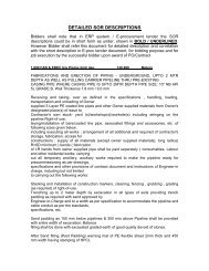
standard specification for fabrication and erection of piping
standard specification for fabrication and erection of piping
standard specification for fabrication and erection of piping

You also want an ePaper? Increase the reach of your titles
YUMPU automatically turns print PDFs into web optimized ePapers that Google loves.
STANDARD<br />
SPECIFICATION FOR<br />
FABRICATION<br />
AND<br />
ERECTION OF PIPING
CONTENTS<br />
1. GENERAL<br />
2. PRE-FABRICATION<br />
3. ERECTION<br />
4. LAYING OF UNDER GROUND PIPING<br />
5. INSPECTION<br />
6. TESTING<br />
7. RECORDS<br />
8. PAYMENT
Std. spec <strong>for</strong> earth work <strong>for</strong> U/G <strong>piping</strong><br />
Std. spec. <strong>for</strong> welding<br />
Code <strong>for</strong> petroleum Piping ANSI B 31.3/IS 10234<br />
<strong>piping</strong><br />
Code <strong>of</strong> procedure <strong>for</strong> manual IS: 823<br />
Metal arc welding <strong>of</strong> mild<br />
Steel <strong>for</strong> structural work.<br />
Welder qualification ASME – Sec. IX<br />
All codes referred shall be the latest editions. The contractor shall bear the cost <strong>of</strong> repair, changes,<br />
replacements etc. due to non-compliance with the <strong>st<strong>and</strong>ard</strong>s, codes <strong>and</strong> the tender or due to<br />
disregard <strong>of</strong> the instructions given by the Engineer in charge.<br />
2. PRE-FABRICATION<br />
The contractor shall fabricate all pipe work in con<strong>for</strong>mity with the requirements <strong>of</strong> pertinent general<br />
arrangement drawing <strong>and</strong> <strong>specification</strong>. Where specific details <strong>of</strong> <strong>fabrication</strong> are not indicated<br />
on the drawings or not specified herein <strong>fabrication</strong> <strong>and</strong> <strong>erection</strong> shall be done in accordance with<br />
the code <strong>for</strong> petroleum refinery <strong>piping</strong> ANSI B 31.3 latest edition.<br />
The contractor shall be reasonable <strong>for</strong> working to the exact dimensions as shown on the drawings<br />
irrespective <strong>of</strong> individual tolerances permissible. Where errors <strong>and</strong> /or omissions occur on the<br />
drawings, it shall be the contractor’s responsibility to notify the Engineer in charge prior to<br />
<strong>fabrication</strong> or <strong>erection</strong>. Dimensional tolerance <strong>for</strong> <strong>fabrication</strong> shall be as per <strong>st<strong>and</strong>ard</strong>.<br />
1. GENERAL<br />
This <strong>specification</strong> is intended to cover the technical requirements <strong>for</strong> the execution <strong>of</strong> <strong>piping</strong> pre<strong>fabrication</strong>,<br />
assembly <strong>and</strong> <strong>erection</strong> <strong>of</strong> the entire pipe work defined hereunder <strong>for</strong> product /water<br />
pipe line.<br />
2. Scope<br />
-Fabrication <strong>and</strong> <strong>erection</strong> <strong>of</strong> all <strong>piping</strong> systems from <strong>piping</strong> materials supplied by owner in<br />
accordance with this <strong>specification</strong> <strong>and</strong> applicable drawings <strong>and</strong> <strong>st<strong>and</strong>ard</strong>s.<br />
-Testing <strong>and</strong> flushing<br />
-Fabrication <strong>and</strong> <strong>erection</strong> <strong>of</strong> supporting elements i.e. shoes, guides, stop anchors, clips, cradles<br />
etc. including applying one coat <strong>of</strong> red oxide zinc chromate primer.<br />
-Fabrication <strong>and</strong> <strong>erection</strong> <strong>of</strong> supporting fixtures i.e. brackets, cantilever struts etc. including<br />
application <strong>of</strong> one coat <strong>of</strong> red oxide zinc chromate primer.<br />
-Coating & wrapping <strong>of</strong> underground <strong>piping</strong>.<br />
-Fabrication <strong>and</strong> <strong>erection</strong> <strong>of</strong> drain assemblies.<br />
-All <strong>piping</strong> systems shall be fabricated, installed, flushed, <strong>and</strong> tested in accordance with this<br />
<strong>specification</strong> <strong>and</strong> applicable codes / drawings / <strong>st<strong>and</strong>ard</strong>s. Any deviation from the <strong>specification</strong><br />
<strong>and</strong> drawing shall be permitted only after obtaining the written approval <strong>of</strong> the Engineer in<br />
charge.<br />
Applicable Codes & St<strong>and</strong>ards<br />
Std. Spec. <strong>for</strong> coating <strong>and</strong> Wrapping <strong>of</strong> U/G <strong>piping</strong>.
2.2 Alignment<br />
The pipes to be joined by welding shall be aligned correctly with the existing tolerances on<br />
diameters, wall thickness <strong>and</strong> out <strong>of</strong> roundness. The same alignment shall be preserved during<br />
welding. For the internal misalignment due to difference in wall thickness <strong>of</strong> the mating<br />
components exceeding 1/16”, the component with the higher wall thickness shall be internally<br />
machined / grounded as per <strong>st<strong>and</strong>ard</strong>, so that the adjoining surfaces are approximately flushed.<br />
2.4 Layout, Cutting & Fitting-up<br />
For laying out headers, tees, laterals <strong>and</strong> other irregular details, cutting templates shall be used to<br />
ensure accurate cutting <strong>and</strong> proper fit up.<br />
All cutting shall follow the outline <strong>of</strong> the templates.<br />
Machine cut bevels to <strong>for</strong>m the welding groove are preferred in carbon steel pipe. However,<br />
smooth, clean, slag free, flame cut bevel is acceptable.<br />
Tack welds with full penetration shall be used <strong>and</strong> shall become the part <strong>of</strong> the finished weld.<br />
Defective welds or tack welds with lack <strong>of</strong> penetration are not acceptable <strong>and</strong> shall be chipped /<br />
ground out. No temporary weld attachment shall be with extended clamps / attachments.<br />
2.5 Other alignment considerations<br />
All flange facing shall be true <strong>and</strong> perpendicular to the axis <strong>of</strong> the pipe to which they are attached.<br />
Flange bolt holes shall straddle the normal centre<br />
Lines unless different orientation is shown in drawings to match the equipment connections<br />
etc.tolerances on <strong>fabrication</strong> shall be as per <strong>st<strong>and</strong>ard</strong>.<br />
2.6 Mitre Bends & Fabricated Reducer<br />
The specific application <strong>of</strong> welded mitre bends <strong>and</strong> fabricated reducers shall be governed by the<br />
<strong>piping</strong> material <strong>specification</strong>s to be furnished to the contractor. The angle <strong>of</strong> the each cut<br />
segment shall be 15deg, 30deg, 30deg <strong>and</strong> 60deg <strong>for</strong> right angle bends (4 piece mitres).<br />
The <strong>piping</strong> rates shall be inclusive <strong>of</strong> <strong>erection</strong> <strong>of</strong> mitre bends <strong>and</strong> <strong>fabrication</strong> <strong>of</strong> reducers.<br />
However, the contractor shall be paid separately <strong>for</strong> <strong>fabrication</strong> <strong>of</strong> bends where required.<br />
2.7 Pipe joints<br />
The relevant <strong>piping</strong> class attached to each line specifies the type <strong>of</strong> pipe joints to be adopted in<br />
construction in all <strong>piping</strong> systems. In general, joining <strong>for</strong> lines 2” <strong>and</strong> above in utility <strong>piping</strong><br />
system shall be accomplished by butt welding connections. Pipe lines 1 ½” <strong>and</strong> below shall have<br />
socket welded / butt welded / screwed joints as specified in the <strong>piping</strong> materials <strong>specification</strong>s.<br />
Butt welded joints shall be as per <strong>st<strong>and</strong>ard</strong>.<br />
In general, flanged connections shall be used at connections to all equipment <strong>and</strong> where required<br />
<strong>for</strong> ease <strong>of</strong> <strong>erection</strong> <strong>and</strong> maintenance purposes.<br />
2.8 Cleaning <strong>of</strong> <strong>piping</strong><br />
On completion <strong>of</strong> <strong>fabrication</strong>, all pipes <strong>and</strong> fittings shall be cleaned inside <strong>and</strong> outside by suitable<br />
means (Mechanical cleaning tool, wire brush, etc.) be<strong>for</strong>e <strong>erection</strong> to ensure that assembly is free<br />
from all loose <strong>for</strong>eign material such as scale, s<strong>and</strong>, weld, spatter particles, cutting chips, etc.
All field fabricated <strong>piping</strong> shall also be cleaned at the completion <strong>of</strong> the <strong>fabrication</strong>. All burrs,<br />
welding circles <strong>and</strong> weld spatter shall be removed by any suitable means (mechanical tools, wire<br />
brush etc.)<br />
Both shop <strong>and</strong> field fabricated <strong>piping</strong> shall be blown out with compressed air at the termination <strong>of</strong><br />
cleaning <strong>and</strong> capped.<br />
Cleaning requirements <strong>for</strong> special services, if any, shall be as specified in the <strong>piping</strong> material<br />
<strong>specification</strong>s.<br />
Per<strong>for</strong>mances <strong>of</strong> welds <strong>and</strong> heat treatment<br />
All welding <strong>and</strong> heat treatment shall be per<strong>for</strong>med in accordance with the welding <strong>specification</strong>s<br />
detailed elsewhere.<br />
3. ERECTION<br />
3.1 The intent <strong>of</strong> pre-<strong>fabrication</strong> at the shop is to accelerate progress <strong>of</strong> pipe work <strong>and</strong> to minimize<br />
working the field. Such pre-<strong>fabrication</strong> should be based on approved isometric <strong>and</strong> <strong>piping</strong><br />
layouts furnished to the contractor. Field weld is indicated by FW on isometrics. Field weld<br />
means position weld <strong>of</strong> prefabricated piece at site or near the plant. However the contractor shall<br />
bear in mid that there can be variations in dimensions between those appearing in the isometrics /<br />
layouts <strong>and</strong> those actually occurring at the site due to minor variations in the location <strong>of</strong><br />
equipment, inserts, etc. The contractor shall, there<strong>for</strong>e, provide adequate field joints, if required,<br />
other than shown in isometric <strong>and</strong> fit-in sections permitting the pre-assembly to be installed<br />
without any modification. In any case no extra clamps will be entertained on this account.<br />
All <strong>piping</strong> shall be routed <strong>and</strong> located as shown in <strong>piping</strong> drawings keeping in view the <strong>piping</strong><br />
<strong>specification</strong>s. No deviations from the arrangement shown shall be permitted without the<br />
express consent <strong>of</strong> the Engineer in charge.<br />
a) While fitting up mating flanges, care shall be exercised to properly align the pipes <strong>and</strong> to check<br />
the flanges <strong>for</strong> trueness, so that faces <strong>of</strong> the flanges can be pulled up together without inducing<br />
any stresses at the pipes <strong>and</strong> equipment nozzles. The bolt holes <strong>of</strong> flanges in the vertical plane<br />
shall straddle the vertical centre line <strong>of</strong> the pipe in the erected position <strong>and</strong> <strong>for</strong> flanges in the<br />
horizontal plane, the bolt holes shall straddle horizontal plane unless otherwise indicated on the<br />
drawings<br />
b) Flanged connections at the pump, turbines, compressors shall be made in such a way as<br />
not to induce any stresses due to mis-alignment, excessive gap etc. The final tightening shall be<br />
redone when the machines are aligned completely <strong>and</strong> specifically authorized by the Engineer in<br />
charge. Temporary protective covers shall be provided at all flanged connections <strong>of</strong> pumps,<br />
compressors, turbines <strong>and</strong> other similar equipment until the <strong>piping</strong> is finally connected.<br />
Slopes specified <strong>for</strong> various lines in the drawings shall be maintained by the contractor. In case<br />
the contractor s unable to maintain the indicated slope he shall check the sagging <strong>of</strong> the pipe with<br />
a precision spirit level. Vents <strong>and</strong> drains are shown in the isometric <strong>of</strong> each line <strong>and</strong> these are<br />
intended, during hydrostatic test, <strong>for</strong> releasing the trapped air <strong>and</strong> draining out the test fluid after<br />
testing. Valved vents <strong>and</strong> drains are also shown wherever required. The contractor shall provide<br />
vents <strong>and</strong> drains connections even when these are not shown in the drawings <strong>and</strong> are found
necessary by the Engineer in charge <strong>for</strong> process lines. The details <strong>for</strong> the type <strong>of</strong> connections to<br />
be adopted shall be given to the contractor at the time <strong>of</strong> work.<br />
After the <strong>piping</strong> is erected in final position, it shall be cleaned, tested <strong>for</strong> tightness <strong>and</strong> kept dry<br />
wherever instructed, as described in this <strong>specification</strong>.<br />
Valves<br />
The valve spindle positions are shown in the arrangement drawings <strong>and</strong> the contractor shall be<br />
required to follow them. He shall, however, bring it to the notice <strong>of</strong> the Engineer in charge in<br />
case he encounters some difficulty in installing them.<br />
Where practicable <strong>and</strong> except when otherwise shown on the drawings, valve stems shall be<br />
installed in a vertical direction <strong>and</strong> shall not be installed with stems below the horizontal axis.<br />
Supports<br />
Supports, guides <strong>and</strong> anchors <strong>for</strong> <strong>piping</strong> shall be fabricated <strong>and</strong> provided as shown in the<br />
drawings. No anchors on <strong>piping</strong> shall be used except at locations shown in the drawings. The<br />
pipe shall be secured firmly at anchor supports.<br />
Fabrication <strong>and</strong> <strong>erection</strong> <strong>of</strong> supporting elements <strong>and</strong> structural fixtures wherever required <strong>and</strong><br />
pointed out by the Engineer in charge, whether indicated in drawing or not, to prevent vibration,<br />
excess sag etc. shall be carried out by the contractor. No separate payment will be made <strong>for</strong><br />
erecting <strong>of</strong> these additional supports <strong>and</strong> it will be deemed as part <strong>of</strong> <strong>piping</strong> <strong>erection</strong> work.<br />
4. LAYING OF UNDERGROUND PIPING<br />
The Contractor shall lay the underground <strong>piping</strong> in accordance with the following clauses <strong>and</strong> as<br />
per the <strong>piping</strong> arrangement drawings/stetches issued during the course <strong>of</strong> construction. Coating<br />
<strong>and</strong> wrapping <strong>of</strong> the underground lines shall be in accordance with <strong>specification</strong>.<br />
The contractor shall dig the pipe line trenches where necessary according to the drawing, true to<br />
the line <strong>and</strong> gradient as per <strong>specification</strong>s <strong>and</strong> as directed by the Engineer-in-charge.<br />
The contractor shall be responsible <strong>for</strong> correct layout <strong>and</strong> gradient <strong>of</strong> the line. Errors, if any, shall<br />
be rectified by the Contractor at his own cost.<br />
Trenching: (Refer <strong>specification</strong> <strong>for</strong> Earthwork in underground <strong>piping</strong>)<br />
The trench shall be cut true to the line leveled with the help <strong>of</strong> sight rails provided at every 30 M at<br />
change <strong>of</strong> direction, gradient <strong>and</strong> at any suitable distance as directed by Engineer in charge.<br />
If the trench is excavated below the required level indicated in the drawing, the extra depth shall<br />
be filled with concrete or approved equivalent material as directed by the Engineer in charge at<br />
no extra cost to owner.<br />
The trench shall be excavated so as to provide an average cover <strong>of</strong> 1000 mm or equal to the<br />
diameter <strong>of</strong> the largest pipe to be laid in the trench, or as shown in drawings whichever is greater.<br />
The average cover will be reckoned from top <strong>of</strong> the pipe <strong>of</strong> the largest diameter to be laid in the<br />
trench, to the finished grade. The width <strong>of</strong> the trench shall be sufficient to give free working
space on each side <strong>of</strong> the pipe. The free working space shall con<strong>for</strong>m to IS: 783. Generally it<br />
shall not be less than 150 mm on either side or 1/3 <strong>of</strong> dia <strong>of</strong> pipe whichever is greater.<br />
No excavated material shall be deposited within 1.5 metres from the excavated trench.<br />
In case <strong>of</strong> road cutting, all material, i.e. metal, bricks etc. shall be taken out carefully <strong>and</strong> kept<br />
separately <strong>for</strong> reuse <strong>and</strong> road work shall be redone upto the original level prior to cutting the road<br />
with the excavated road materials after laying <strong>and</strong> testing <strong>of</strong> the pipe line within 10 days from the<br />
date <strong>of</strong> starting the work at the cost <strong>of</strong> the contractor. The contractor shall provide suitable sings<br />
<strong>and</strong> barricades to prevent accidents. He shall also provide reasonable by pas at his own cost<br />
when a road is cut <strong>for</strong> laying pipeline.<br />
During excavation, if some obstacle is met with, the same shall be reported to the Engineer in<br />
charge <strong>and</strong> dealt with as instructed by him.<br />
The contractor shall dewater, shore or do whatever might be required to excavate the trench, install<br />
the pipe in it <strong>and</strong> backfill the trench, in accordance with the <strong>specification</strong>s at no extra cost to the<br />
owner. Dewatering shall be done in advance <strong>of</strong> the laying <strong>of</strong> the pipe to allow adequate<br />
inspection <strong>of</strong> padding <strong>of</strong> the bottom if required <strong>and</strong> dewatering shall be continued throughout<br />
during laying <strong>of</strong> the pipe an backfilling <strong>of</strong> the trench.<br />
In muddy slushy ground, the bed shall be provided with a layer <strong>of</strong> a s<strong>and</strong> or lean concrete as<br />
directed by the Engineer in charge.<br />
The trench shall follow the gradient <strong>of</strong> pipeline as specified in the drawing. The contractor shall<br />
keep the trench in good condition. Until the pipe is laid <strong>and</strong> tested, no extra claim shall be<br />
entertained due to its caving or setting down either be<strong>for</strong>e or after the pipe is laid. All materials<br />
to shore the trench in order to prevent caving are to be furnished <strong>and</strong> removed by the Contractor<br />
at no extra cost to the owner.<br />
In case pipe is lowered in caved trench <strong>and</strong> back filled be<strong>for</strong>e being inspected by the Engineer in<br />
charge, the contractor shall re-excavate the trench, <strong>for</strong> inspection <strong>and</strong> backfill it at his own cost.<br />
5.0 Lowering <strong>and</strong> laying<br />
The pipe shall be lowered either by mechanical method or by h<strong>and</strong> when the trench is ready <strong>and</strong><br />
bottom <strong>of</strong> the trench is graded as per required pipe laying conditions <strong>and</strong> <strong>specification</strong>s.<br />
5.1 By Machine<br />
The shop coated pipe, already transported to the pipe laying site / convenient length <strong>of</strong> pip<br />
assembly coated <strong>and</strong> wrapped near the trench after hydrostatic testing shall be placed on clean<br />
square cut skids suitably spaced so as to keep the pipe way from touching the ground. The pipe<br />
may be lowered down in the trench by the launcher cranes, with sufficient care to protect the<br />
coating <strong>and</strong> wrapping <strong>of</strong> the pipelines.<br />
At tie in welds <strong>and</strong> other places, the contractor shall clean, prime, coat <strong>and</strong> wrap manually. Also<br />
short sections <strong>of</strong> pipelines which are impracticable to shop treat may be h<strong>and</strong> treated but only on<br />
the prior written approval <strong>of</strong> the Engineer in charge.
5.2 By H<strong>and</strong><br />
The pipe may be lowered with the help <strong>of</strong> tripods <strong>and</strong> chain pulley blocks into the trench<br />
immediately after the coating <strong>and</strong> wrapping. However, if in the opinion <strong>of</strong> the Engineer in<br />
charge that the temperature conditions do not allow direct lowering, then the pipes shall be set<br />
down on clear square cut skids. The skids shall be so spaced as to keep the pipe away from<br />
touching the ground.<br />
Method & Time <strong>of</strong> Lowering Pipe<br />
Under favourable temperature, conditions <strong>and</strong> using methods which will not damage coating, the<br />
pipe may be lowered into the trench.<br />
Pipe previously set on skids, because <strong>of</strong> un-favourable temperature conditions shall be lowered<br />
into the trench normally in the cool <strong>of</strong> the morning <strong>and</strong> only when the temperature <strong>of</strong> the pipe is<br />
below the s<strong>of</strong>tening point <strong>of</strong> the coating materials.<br />
All skid marks <strong>and</strong> other places <strong>of</strong> damage shall be thoroughly examined to ensure proper patching<br />
where necessary, be<strong>for</strong>e the pipe is finally lowered into the trench.<br />
6.0 H<strong>and</strong>ling coated pipe<br />
Coated pipe shall not be placed in trench until cave in plugs, hard clods; stones, skids, welding<br />
rods etc. have been removed there from. Where the trench has a hard or jagged bottom,<br />
sufficient fine dirt or s<strong>and</strong> shall be placed therein, be<strong>for</strong>e the pipe is lowered.<br />
Coated pipe shall not be h<strong>and</strong>led or moved by means <strong>of</strong> cable or chains or by praying with skids<br />
or bars, it shall be tightened <strong>and</strong> lowered by using lowering in belts <strong>of</strong> a <strong>st<strong>and</strong>ard</strong> width <strong>and</strong><br />
design <strong>for</strong> the size <strong>of</strong> pipe being h<strong>and</strong>led.<br />
Coated pipe shall not be dragged along the ground or otherwise h<strong>and</strong>led in a manner that will be<br />
detrimental to the coating.<br />
Lining up <strong>and</strong> welding<br />
The ends <strong>of</strong> the pipe line shall be kept securely closed to prevent entry <strong>of</strong> any <strong>for</strong>eign material /<br />
moisture after lowering into the trench.<br />
Be<strong>for</strong>e making joint, the pipe shall be carefully laid so as to be perfectly aligned in both plan <strong>and</strong><br />
pr<strong>of</strong>ile, <strong>and</strong> the end closure provided shall be removed. Tie in shall be made in the coolness <strong>of</strong><br />
the morning or when the ambient temperature is not exceeding 29 deg C or s<strong>of</strong>tening<br />
temperature <strong>of</strong> the coating material whichever is less. All beveling aligning <strong>and</strong> welding shall be<br />
in accordance with the welding <strong>specification</strong> given in the tender.<br />
Free access shall be provided <strong>for</strong> the welding <strong>of</strong> the circumferential joints by increasing the width<br />
<strong>and</strong> depth <strong>of</strong> the trench at these points. There should be no construction to the welder from any<br />
side so that good welded joint is obtained.<br />
Testing & coating wrapping
The completed system shall then be tested as per clause 6 <strong>and</strong> the field welded joints coated <strong>and</strong><br />
wrapped as per <strong>specification</strong>.<br />
7.0 Back Filling<br />
After testing <strong>and</strong> inspection <strong>of</strong> the pipeline to the entire satisfaction <strong>of</strong> the Engineer in charge, the<br />
trench shall be back filled with the excavated material. No trench shall be back filled without the<br />
approval <strong>of</strong> the Engineer in charge. Backfilling with the excavated material shall be done in<br />
layers <strong>of</strong> 200 mm well watered <strong>and</strong> rammed to avoid any settling afterwards.<br />
The contractor shall place soil over the trench to such a height as well as in opinion <strong>of</strong> the Engineer<br />
in charge, to provide adequately <strong>for</strong> future settlement <strong>of</strong> the trench backfill.<br />
If due to exigencies <strong>of</strong> the work, some portion <strong>of</strong> the pipeline is backfilled without approval <strong>of</strong> the<br />
Engineer in charge, the engineer in charge shall have the right to order uncovering <strong>of</strong> the pipe <strong>for</strong><br />
examination <strong>and</strong> the cost <strong>of</strong> such uncovering shall be borne by the Contractor.<br />
The backfill material shall free from stone pieces.<br />
Surplus excavated soil or rubbish material shall be removed by the Contractor at his own cost to a<br />
place designated by the Engineer in charge.<br />
When the trench has been dug through roads, all backfill shall be thoroughly compacted. In<br />
certain cases, special compaction methods may be required by the Engineer I charge. This shall<br />
be done by the contractor at no extra cost to the owner.<br />
When the trench has been dug through unlined ditches the backfill shall be thoroughly compacted<br />
in 150 mm layers <strong>for</strong> a distance <strong>of</strong> 1.50 m beyond the outside banks <strong>of</strong> the ditch on either side.<br />
The banks <strong>of</strong> the ditch shall also be compacted in 150 mm layers at no extra cost to the owner.<br />
After the roads have been already graded <strong>and</strong> if they are trenched or otherwise disturbed by the<br />
Contractor during laying <strong>of</strong> the pipe lines, the contractor shall restore the road to its original level<br />
<strong>and</strong> condition. In the event, the contractor is required to place extra fill, gravel, or other special<br />
materials it shall be done by him without any extra cost to the owner.<br />
Clean up <strong>of</strong> surroundings<br />
As soon as the backfill is completed, the contractor shall immediately clean up the adjoining area<br />
by removing all surplus <strong>and</strong> defective material <strong>and</strong> dispose <strong>of</strong> all refuse such as spurs, sheet-iron,<br />
broken skids, etc. to the complete satisfaction <strong>of</strong> the Engineer in charge.<br />
The earth on both sides <strong>of</strong> the pipeline trench which has been disturbed during the construction <strong>of</strong><br />
the pipe line shall be smoothened <strong>and</strong> left in a condition satisfactory to the Engineer in charge.<br />
8.0 INSPECTION<br />
General<br />
Owner’s inspector shall have free access to all places where the work is being done or any other<br />
thing <strong>and</strong> place concerned with the work.
Owner is entitled to send his own inspector, to field or shops where pre-<strong>fabrication</strong> <strong>and</strong> <strong>erection</strong> <strong>of</strong><br />
pipe lines are being done, with the following functions but not limited to :<br />
i) To check that the welding per<strong>for</strong>mance <strong>and</strong> welding equipments used on the job are suitable <strong>and</strong><br />
con<strong>for</strong>m to relevant <strong>st<strong>and</strong>ard</strong>s.<br />
ii) To supervise welding procedure qualification.<br />
iii) To supervise welder per<strong>for</strong>mance qualification.<br />
iv) To check whether welding is con<strong>for</strong>ming to relevant <strong>specification</strong> <strong>and</strong> the practice<br />
construction practice.<br />
To check any other per<strong>for</strong>mance to ensure quality <strong>of</strong> work.<br />
Contractor shall notify sufficiently in advance the commencement <strong>of</strong> qualification tests, welding<br />
work <strong>and</strong> acceptance tests, to enable the Owner’s Inspector to supervise the same.<br />
Contractor shall provide the Owner’s Inspector with all facilities necessary <strong>for</strong> carrying out his<br />
work at no extra cot to the owner.<br />
Approval from the Owner’s Inspector shall not relieve the contractor partially or fully <strong>of</strong> his<br />
responsibilities <strong>and</strong> guarantees under this contract.<br />
Visual Inspection<br />
Inspection <strong>of</strong> all welds shall be carried out as per ANSI B 31.3. Finished welds shall be visually<br />
inspected <strong>for</strong> parallel <strong>and</strong> axial misalignment <strong>of</strong> the work, cracks, inadequate penetration, un<br />
repaired burn-through, dimensions, <strong>and</strong> other surface defects, <strong>and</strong> it shall present a neat workman<br />
like appearance. Under cutting adjacent to the final bead on the outside <strong>of</strong> the pipe shall not<br />
exceed 0.8 mm in depth <strong>of</strong> 12 ½% <strong>of</strong> the pipe wall thickness, which ever is smaller <strong>and</strong> the<br />
cumulative length shall not be more than 50 mm in any continuous 300 mm length <strong>of</strong> weld.<br />
Repairs or removal <strong>of</strong> defects<br />
Defects which are not within the acceptable limits shall be removed from the joint completely by<br />
chipping or grinding.<br />
When the whole joint is found unacceptable, the weld <strong>and</strong> the ends <strong>of</strong> the joints shall be restored<br />
according to relevant clauses under <strong>fabrication</strong>.<br />
No repair shall be carried out without prior authorization <strong>of</strong> the Engineer in charge.<br />
9.0 TESTING<br />
General<br />
The field test pressure shall not be less than the greatest <strong>of</strong> the following:<br />
a) 1 ½ times the maximum sustained operating pressure.<br />
b) 1 ½ times the maximum pipeline static pressure <strong>and</strong><br />
Sum <strong>of</strong> the maximum sustained operating pressure or the maximum pipe line static pressure <strong>and</strong><br />
the maximum calculated surge pressure.
The field test pressure shall wherever possible be not less than two thirds <strong>of</strong> the works test<br />
pressure <strong>and</strong> shall be applied <strong>and</strong> maintained <strong>for</strong> at least four hours.<br />
Where the field test pressure is less than two thirds the works test pressure, the period <strong>of</strong> test shall<br />
be increased to at least 24 hours. The test pressure shall be gradually raised at the rate <strong>of</strong> nearly<br />
kg / cm 2 / minute.<br />
All underground / above ground pipes shall be tested <strong>for</strong> leakages to a minimum hydrostatic test<br />
pressure <strong>of</strong> 10 kg/ cm2 gauge.<br />
The testing shall be carried out in convenient section as approved by the Engineer in charge. The<br />
joints <strong>of</strong> the pipe connecting the testing sections shall be 100% radiographed.<br />
If some defect is noticed during the hydrostatic testing, the same shall be brought to the Notice <strong>of</strong><br />
Engineer in charge. Joints, if leaking, shall be rectified as per the welding <strong>specification</strong>s <strong>and</strong><br />
instructions <strong>of</strong> engineer in charge <strong>and</strong> tested to his satisfaction at no extra cost to the owner.<br />
The engineer in charge shall be notified in advance by contractor <strong>of</strong> all testing. The hydrostatic<br />
testing / flushing <strong>of</strong> all the <strong>piping</strong> shall be carried out by the contractor at his own cost.<br />
Contractor shall make his own arrangements <strong>for</strong> flushing at suitable points as per the instructions<br />
<strong>of</strong> the Engineer in charge. Any extra work / modification on this account shall be done by the<br />
contractor at his own cost.<br />
Test medium<br />
Construction water shall generally be used as the testing medium <strong>for</strong> the hydrostic testing <strong>of</strong><br />
<strong>piping</strong> system.<br />
Cleaning<br />
All systems shall be cleaned <strong>and</strong> flushed free <strong>of</strong> all dirt, debris or loose <strong>for</strong>eign material after<br />
testing.<br />
Temporary Blinds<br />
Open ends <strong>of</strong> <strong>piping</strong> systems such as a pumps or wherever equivalent has been removed or<br />
disconnected prior to hydrostatic testing, or at termination point <strong>of</strong> <strong>piping</strong> branch connections<br />
shall be blinded <strong>of</strong> by temporary blind flange made out <strong>of</strong> 10 mm thick M.S. plate.<br />
Venting:<br />
All <strong>piping</strong> systems <strong>and</strong> equipments shall be properly vented to remove air from system during<br />
filling.<br />
Pressurizing<br />
Pressure shall be applied by means <strong>of</strong> a suitable test pump which shall not be connected to the<br />
system until ready to test. A pressure gauge shall be provided at the pump discharge <strong>for</strong><br />
guidance in bringing the system upto pressure. The pump shall be attended to constantly during<br />
the test by an authorized operator. The pump shall be disconnected after the pressure test is<br />
completed.
The test pressure is to be maintained <strong>for</strong> sufficient time to permit complete inspection <strong>of</strong> the<br />
system under test but in no case shall the time be less than ten minutes. Test shall be considered<br />
complete only when approval is given by the Engineer in charge.<br />
Test Gauges:<br />
Draining<br />
Contractor’s own test gauge shall be installed as close as possible to the lowest point in the system<br />
being tested. Prior to installation, the test gauge shall be checked against a <strong>st<strong>and</strong>ard</strong> gauge or<br />
calibrated with the aid <strong>of</strong> a dead weight tester. Calibration <strong>of</strong> test gauges shall be the<br />
responsibility <strong>of</strong> the contractor.<br />
All lines <strong>and</strong> equipments shall be completely drained after the hydrostatic test <strong>of</strong> a system has<br />
been completed. High point vents shall be open to prevent excessive vacuum <strong>and</strong> permit<br />
complete draining.If it becomes necessary to leave a system filled with the testing medium <strong>for</strong><br />
any abnormal length <strong>of</strong> time, such as venting shall be made to provide <strong>for</strong> possible liquid<br />
expansion with change in ambient temperatures.<br />
10.0 RECORDS<br />
Records in triplicate shall be made <strong>for</strong> each <strong>piping</strong> system as follows:<br />
10.1 In case <strong>of</strong> underground <strong>piping</strong>, layouts giving actual elevations or pipeline as laid.<br />
10.2 Test certificates containing date or test, identification <strong>of</strong> the <strong>piping</strong> system, test fluid used, test<br />
pressure <strong>and</strong> approval <strong>of</strong> owner’s inspector.<br />
Certificates <strong>for</strong> flushing containing flushing medium used, identification <strong>of</strong> the <strong>piping</strong> system, date<br />
<strong>of</strong> flushing <strong>and</strong> approval by owner’s inspector.<br />
PAYMENT<br />
Payment <strong>for</strong> <strong>piping</strong> shall be based on linear measurements calculated on the basis <strong>of</strong> the execution<br />
drawings. The length shall be measured along the centre lines <strong>of</strong> pipes, centre lines <strong>of</strong> bends <strong>and</strong><br />
elbows, tees, reducer, SW, flanged joints. All types <strong>of</strong> valves shall be excluded from this<br />
measurement. Branch connections shall be measured from the outer surface <strong>of</strong> the header.<br />
The payment shall be made on per metre basis <strong>of</strong> <strong>piping</strong> work erected, measured to the nearest<br />
centimeter.<br />
The unit rates <strong>for</strong> the underground <strong>piping</strong> shall be inclusive <strong>of</strong> earthwork excavation, backfilling,<br />
<strong>and</strong> compaction, disposal <strong>of</strong> surplus earth, coating <strong>and</strong> wrapping including supply <strong>of</strong> materials.<br />
The unit rates <strong>for</strong> above ground carbon steel <strong>piping</strong> shall be exclusive <strong>of</strong> <strong>erection</strong> <strong>of</strong> all types <strong>of</strong><br />
supports but inclusive <strong>of</strong> supply <strong>of</strong> necessary bolts nuts <strong>and</strong> washers gaskets etc as per respective<br />
<strong>specification</strong>.<br />
Payment <strong>for</strong> the installation <strong>of</strong> sluice valves, check valves, butterfly valves, expansion bellows<br />
will be made on number basis <strong>and</strong> the unit rates shall be inclusive <strong>of</strong> supply <strong>of</strong> necessary bolts<br />
nuts, washers <strong>and</strong> gaskets, etc.
All <strong>piping</strong> attachments, such as coupling, nipples, thermo wells etc. shall be installed by the<br />
Contractor as per the <strong>piping</strong> work <strong>and</strong> no separate payment shall be made <strong>for</strong> such work.<br />
However, extension on such attachments such as vents <strong>and</strong> drains will be measured <strong>and</strong> paid as<br />
applicable <strong>for</strong> the respective size <strong>and</strong> category <strong>of</strong> <strong>piping</strong> / valves.<br />
Fabrication <strong>of</strong> mitre bend, concentric <strong>and</strong> eccentric reducers fabricated from pipes supplied by<br />
owner, <strong>and</strong> <strong>fabrication</strong> <strong>of</strong> flanges from plates supplied by owner, will be paid at respective unit<br />
rates. However, <strong>erection</strong> <strong>of</strong> these items will be along with <strong>piping</strong> <strong>of</strong> the respective size <strong>and</strong> no<br />
separate payment will be made <strong>for</strong> <strong>erection</strong>. The reducers will be measured <strong>and</strong> paid along with<br />
the <strong>piping</strong> <strong>of</strong> large diameter.<br />
No separate payment will be made <strong>for</strong> making pipe to pipe branch connection crosses with or<br />
without rein<strong>for</strong>cing pads <strong>and</strong> the unit rates <strong>for</strong> <strong>piping</strong> are deemed to include all such work.<br />
Fabrication, installation <strong>and</strong> removal <strong>of</strong> temporary spool pieces etc. to aid contractor’s work such<br />
as <strong>fabrication</strong>, <strong>erection</strong>, flushing testing, <strong>and</strong> etc. will neither be measured nor paid separately.<br />
The same is deemed to be included in the unit rates <strong>for</strong> <strong>piping</strong>.<br />
Payment <strong>for</strong> carrying out radiographic examination shall be based on linear length <strong>of</strong> the welded<br />
joint radiographed. Repeat radiography / additional radiography required due to contractor’s<br />
fault / poor per<strong>for</strong>mance <strong>of</strong> his welders, defective films shall be done at contractor’s own cost.<br />
WELDING SPECIFICATION FOR THE FABRICATION OF PIPING<br />
(Above Ground Portion)<br />
1. GENERAL<br />
This <strong>specification</strong> shall be followed <strong>for</strong> the <strong>fabrication</strong> <strong>of</strong> all types <strong>of</strong> welded joints <strong>of</strong><br />
carbon steel <strong>and</strong> alloy steel <strong>piping</strong> system within the battery limits <strong>of</strong> the plant.<br />
The welded pipe joints shall include the following:<br />
a) All pipe joints <strong>of</strong> the longitudinal <strong>and</strong> circumferential butt welded <strong>and</strong> socket welded<br />
types.<br />
b) Attachments <strong>of</strong> <strong>for</strong>gings, flanges <strong>and</strong> other supports to pipes.<br />
c) Welded manifold headers <strong>and</strong> other sub-assemblies<br />
d) Welded branch connections with or without rein<strong>for</strong>cing pads.<br />
e) Joints in welded / fabricated <strong>piping</strong> components.<br />
f) The attachments <strong>of</strong> smaller connections <strong>for</strong> vents, drain drips <strong>and</strong> other instrument<br />
tappings.<br />
Any approval granted by the Engineer-in-charge or Owner's inspector, shall not relieve the<br />
Contractor <strong>of</strong> his responsibilities <strong>and</strong> guarantee.<br />
This <strong>specification</strong> shall not be applicable <strong>for</strong> welding <strong>of</strong> pipelines <strong>for</strong> transportation <strong>of</strong> liquid<br />
petroleum <strong>and</strong> other similar products.<br />
2. APPLICATION CODES &STANDARDS :<br />
All welding work, equipments <strong>for</strong> welding, heat treatment, other auxiliary functions <strong>and</strong> the<br />
welding personnel shall meet the requirements <strong>of</strong> the latest editions <strong>of</strong> the following expected<br />
<strong>st<strong>and</strong>ard</strong>s <strong>and</strong> procedures unless otherwise specified in the Welding <strong>specification</strong> chart <strong>and</strong>
the technical notes attached. In the case <strong>of</strong> conflicting requirements, the requirements<br />
mentioned in welding <strong>specification</strong> chart / Technical Notes shall be applicable.<br />
a) Chemical Plant <strong>and</strong> Petroleum Refinery Piping - ANSI:B31.3<br />
b) The Indian Boiler Regulations - I.B.R.<br />
relevant code <strong>of</strong> <strong>fabrication</strong> shall be followed <strong>for</strong> the welding procedures.<br />
i. Welding <strong>and</strong> Brazing Qualifications ASME Sec IX.<br />
ii. Non destructive examination ASME Sec. V<br />
iii. Material Specifications : welding rods, Electrodes <strong>and</strong> filler metals ASME Sec II Part<br />
C<br />
In the event <strong>of</strong> any differences due to the additional requirements mentioned in this <strong>specification</strong>, over<br />
<strong>and</strong> above those obligatory as per codes, this <strong>specification</strong> shall be binding.<br />
3. BASE METAL:<br />
3.1 In general, use <strong>of</strong> carbon steel, alloy steel <strong>and</strong> stainless steel are envisaged. The details <strong>of</strong><br />
the material <strong>specification</strong>s are given in the welding <strong>specification</strong> chart.<br />
3.2 The contractor shall provide the manufacturer's test certificates <strong>for</strong> every heat <strong>of</strong> the<br />
materials supplied by him.<br />
4. WELDING CONSUMABLES<br />
4.1 The contractor shall provide, at his own expense, all the welding consumables necessary <strong>for</strong><br />
the execution <strong>of</strong> the job such as electrodes, filler wires, oxygen, acetylene, argon etc, <strong>and</strong><br />
these should bear the approval <strong>of</strong> the Engineer-in-charge.<br />
4.2 The welding electrodes <strong>and</strong> filler wires supplied by the Contractor shall con<strong>for</strong>m to the class<br />
specified in the welding <strong>specification</strong>s chart. The materials shall be <strong>of</strong> the make approved<br />
by the Engineer-in-charge.<br />
4.3 Electrode qualification test records should be submitted as per the Exhibit –A (attached) in<br />
respect <strong>of</strong> the electrodes tested by the Contractor, <strong>for</strong> obtaining the approval <strong>of</strong> the engineerin-charge.<br />
4.4 The contractor shall submit batch test certificates, from the electrode manufacturers, giving<br />
details <strong>of</strong> physical <strong>and</strong> chemical tests carried out by them, <strong>for</strong> each batch <strong>of</strong> electrode to be<br />
used.<br />
4.5 All electrodes shall be purchased in sealed containers <strong>and</strong> stores properly to prevent<br />
deterioration. The electrodes removed from the containers shall be kept in holding ovens at<br />
temperatures recommended by the electrode manufacturer. 'Out <strong>of</strong> the oven time' on<br />
electrodes, be<strong>for</strong>e they are consumed shall not exceed the limits recommended by the<br />
electrode manufacturer. The electrodes shall be h<strong>and</strong>led with care to avoid any damage to<br />
the flux covering.<br />
4.6 All low hydrogen tupe <strong>of</strong> electrodes shall be rebarked at 350 0 C <strong>for</strong> 1 hour minimum <strong>and</strong><br />
stored in ovens kept at 80-100 0 C be<strong>for</strong>e use. Recommendations <strong>of</strong> the electrode<br />
manufacturer shall be followed if available.<br />
4.7 The electrodes, filler wires <strong>and</strong> flux used shall be free from rust, oil, grease, earth <strong>and</strong> other<br />
<strong>for</strong>eign matter which affect the quality <strong>of</strong> welding.<br />
4.8 Tungsten electrodes used shall con<strong>for</strong>m to SPA 5.12 <strong>specification</strong>.
5. SHIELDING & PURGING GAS :<br />
5.1 Argon gas used in GTA welding <strong>for</strong> shielding purpose shall be 99.995% pure. The purity <strong>of</strong><br />
the gas shall be certified by the manufacturer. The rate <strong>of</strong> flow shielding purpose shall be<br />
established through procedure qualification tests. Normally this rate may be 12-20 CFH.<br />
5.2 Argon gas with a purity level <strong>of</strong> 99.995% shall be used <strong>for</strong> purging.<br />
5.3 When GTAW process alone or a combination <strong>of</strong> GTAW processes is recommended <strong>for</strong> the<br />
production <strong>of</strong> a particular joint, the purging shall be maintained during the root pass <strong>and</strong> <strong>for</strong><br />
the first filling pass to minimize oxidation on the inner side <strong>of</strong> the pipe, unless otherwise<br />
specified in welding <strong>specification</strong> chart.<br />
5.4 Initial purging shall be maintained <strong>for</strong> sufficient period <strong>of</strong> time so that at least 4-5 time the<br />
volume between the dams is displaced, in order to completely remove the entrapped air. In<br />
no case should the initial purging period be less than 10 minutes. High gas pressure should<br />
be avoided.<br />
5.5 After initial purging, the flow <strong>of</strong> the backing gas should be reduced to a point where only a<br />
slight positive pressure prevails. For systems which have a small volume ( upto ½ cubic<br />
foot) to be purged, a gas flow rate <strong>of</strong> 6-CFH is usually adequate. Systems <strong>of</strong> larger volume<br />
may require higher flow rates <strong>and</strong> these should be established procedure qualification tests.<br />
5.6 Gas backing (purging) is not required <strong>for</strong> socket type <strong>of</strong> welded joints.<br />
5.7 Dams, used <strong>for</strong> conserving inert gas during purging, shall be removed after completion <strong>of</strong><br />
the welding, <strong>and</strong> shall be accounted <strong>for</strong>. Wherever, removal <strong>of</strong> dams is not possible after<br />
welding, use <strong>of</strong> water soluble dams should be made.<br />
2. EQUIPMENTS & ACCESSORIES :<br />
6.1 The contractor should have the arrangement <strong>of</strong> sufficient number <strong>of</strong> welding <strong>and</strong> cutting<br />
equipments, auxiliaries, <strong>and</strong> accessories <strong>of</strong> sufficient capacities so as to meet the target/<br />
schedule.<br />
6.2 All the equipments <strong>for</strong> per<strong>for</strong>ming the heat treatment, including trans<strong>for</strong>mers, thermocouples,<br />
pyro-meters, automatic temperature recorders with suitable calibration<br />
arrangements etc. shall be provided by the Contractor at his own expense <strong>and</strong> these should<br />
bear the approval <strong>of</strong> the Engineer-in-charge.<br />
6.3 Contractor shall make necessary arrangements at his own expense <strong>for</strong> providing the<br />
radiographic equipments, radiographic films, <strong>and</strong> all the equipments / materials required <strong>for</strong><br />
carrying out the dye-penetrant/ magnetic particle test <strong>for</strong> satisfactory <strong>and</strong> time completion <strong>of</strong><br />
the job.<br />
6.4 Redoing <strong>of</strong> any work necessitated by faulty equipments or operaion used by the Contractor,<br />
will be done at his own expense.<br />
3. WELDING PROCESSES :<br />
7.1 Welding <strong>of</strong> various materials under this <strong>specification</strong> shall be carried out using one or more<br />
<strong>of</strong> the following processes with the approval <strong>of</strong> the Engineer-in-charge.<br />
- Shielded Metal Arc Welding Process (SMAW)<br />
- Gas Tungsten Arc Welding Process (GTAW).<br />
7.2 The welding processes to be employed are given in the welding <strong>specification</strong>s chart. Any<br />
deviation desired by the contractor shall be obtained through the express consent <strong>of</strong> the<br />
Engineer-in-charge.
7.3 Automatic <strong>and</strong> semi-automatic welding processes shall be employed only with the express<br />
approval <strong>of</strong> the Engineer-in-charge. The welding procedure adopted <strong>and</strong> consumables used<br />
shall be specifically approved.<br />
7.4 A combination <strong>of</strong> different welding processes could be employed <strong>for</strong> a particular joint only<br />
after duly qualifying the welding procedure to be adopted <strong>and</strong> obtaining the approval <strong>of</strong><br />
Engineer-in-charge.<br />
4. EDGE PREPARATION :<br />
8.1 The edges to be welded shall be prepared to meet the joint design requirements by any <strong>of</strong><br />
the following methods recommended.<br />
a. Carbon Steel<br />
Gas cutting, machining or grinding methods shall be used. After gas cutting, oxides<br />
shall be removed by chipping or grinding.<br />
b. Low Alloy Steels (containing upto 2 ½ chromium):<br />
Gas cutting, machining or grinding methods shall be used. After cutting, machining or<br />
grinding shall be carried out on the cut surface.<br />
c. High alloy steels, cupro-nickel, nickel alloys, <strong>and</strong> aluminium alloys:<br />
Plasma cutting, machining or grinding methods shall be used. After plasma<br />
cutting, cut surfaces shall be machined or ground smooth.<br />
8.2 Cleaning-<br />
a. The ends to be welded shall be properly cleaned to remove paint, oil, grease, rust, oxides,<br />
s<strong>and</strong>, earth <strong>and</strong> other <strong>for</strong>eign matter. The ends shall be complete dry be<strong>for</strong>e the welding<br />
commences.<br />
b. On completion <strong>of</strong> each run, craters, welding irregularities, slag etc., shall be removed by<br />
grinding <strong>and</strong> chiseling. Wire brushes used <strong>for</strong> cleaning stainless steel joints shall have<br />
stainless steel wires <strong>and</strong> the grinding wheels used <strong>for</strong> grinding stainless steel shall be <strong>of</strong><br />
suitable type. Separate grinding wheels <strong>and</strong> wire brushes should be used <strong>for</strong> carbon steels<br />
<strong>and</strong> stainless steel.<br />
9. ALIGNMENT & SPACING :<br />
9.1 Components to be welded shall be aligned <strong>and</strong> spaced as per the requirements laid down<br />
in applicable code. Special care must be taken to ensure proper fitting <strong>and</strong> alignment<br />
when the welding is per<strong>for</strong>med by GTAW process. Flame heating <strong>for</strong> adjustment <strong>and</strong><br />
correction <strong>of</strong> end is not permitted unless specifically approved by the engineer-in-charge.<br />
9.2 A wire spacer <strong>of</strong> suitable diameter may be used <strong>for</strong> maintaining the weld root opening<br />
while tacking, but it must be removed after tack welding <strong>and</strong> be<strong>for</strong>e laying the root bead.<br />
9.3 For pipes <strong>of</strong> wall thickness 5mm <strong>and</strong> above, the ends to be welded shall be secured in<br />
position with the aid <strong>of</strong> couplers; yokes <strong>and</strong> 'C' clamp to maintain perfect alignment.<br />
Yokes shall be detached after the completion <strong>of</strong> weld, without causing any surface<br />
irregularity. Any irregularity caused on the pipe surface must be suitably repaired to<br />
satisfaction <strong>of</strong> the engineer-in-charge.<br />
9.4 Tack welds, <strong>for</strong> maintaining the alignment, <strong>of</strong> pipe joints shall be executed carefully <strong>and</strong><br />
shall be free from defects. Defective tack welds must be removed prior to the actual<br />
welding <strong>of</strong> the joints.<br />
9.5 Tacks should be equally spaced. Minimum number <strong>of</strong> tacks shall be<br />
2 tacks – <strong>for</strong> 2 ½ '' <strong>and</strong> smaller dia pipes<br />
4 tacks - <strong>for</strong> 3" to 12'' dia. pipes<br />
6'' tacks – <strong>for</strong> 14'' <strong>and</strong> larger dia pipes
9.6 Engineer-in-charge shall check <strong>and</strong> approve the fit-up <strong>and</strong> alignment pipe joint prior to the<br />
commencement <strong>of</strong> welding.<br />
10. WEATHER CONDITIONS :<br />
10.1 The parts being welded <strong>and</strong> the welding personnel should be adequately protected from<br />
rain <strong>and</strong> strong wings. In the absence <strong>of</strong> such a protection no welding shall be carried out.<br />
10.2 During field welding using GTAW process, particular care shall be exercised to prevent<br />
any air current affecting the welding process.<br />
11. WELDING TECHNIQUE :<br />
11.1 Root Pass<br />
a) Root pass shall be made with electrodes/ filler wires recommended in the welding<br />
<strong>specification</strong> chart. For fillet welding root welding shall be done with consumables<br />
recommended <strong>for</strong> filler passes. The preferable size <strong>of</strong> the electrodes is 2.5 mm diameter<br />
(12 SWG) but in any case not greater than 3.25 mm (10 SWG)<br />
b) Upward technique shall be adopted <strong>for</strong> welding pipe held fixed with its axis horizontal.<br />
c) The root pass <strong>of</strong> butt joints should be executed so as to achieve full penetration with<br />
complete fusion <strong>of</strong> the root edges. Weld projection inside the pipe shall not exceed 3<br />
mm, wherever, ___ specified by the applicable code.<br />
d) Any deviation desired from the recommended welding technique <strong>and</strong> electrodes indicated<br />
in the welding <strong>specification</strong> chart should be adopted only after obtaining express approval<br />
<strong>of</strong> the Engineer-in-charge.<br />
e) Welding shall be uninterrupted.<br />
f) While the welding is in progress care should be taken to avoid any klind <strong>of</strong> movement <strong>of</strong><br />
the components, shocks, vibrations <strong>and</strong> stresses to prevent occurrence <strong>of</strong> weld cracks.<br />
g) Peening shall not be used<br />
11.2 Joint Completion<br />
a) Joint shall be completed using the class <strong>of</strong> electrodes, recommended in the Welding<br />
Specification Chart. Size <strong>of</strong> the electrode shall not exceed 4 mm in diameter <strong>for</strong> stainless<br />
steel <strong>and</strong> alloy steels used <strong>for</strong> low temperature applications.<br />
b) Two welds beads shall not be started at the same point in.<br />
c) Butt joints shall be completed with a cover layer that would affect good fusion at the joint<br />
edges <strong>and</strong> a gradual notch free surface.<br />
d) Each weld joint should have a workman like finish.<br />
e) Weld identification work shall be stamped clearly at each joint just adjacent to the weld.<br />
Metal stamping shall not be used as <strong>st<strong>and</strong>ard</strong>. Suitable paint shall be used on thin wall pipes<br />
<strong>for</strong> identification.<br />
f) No painting shall be done until the weld joint has been approved.<br />
11.3 Dissimilar welds<br />
Where welds are to be produced between carbon steels <strong>and</strong> alloy steels, preheat <strong>and</strong> postweld<br />
Heat Treatment requirement shall be those specified <strong>for</strong> corresponding alloy steels <strong>and</strong> electrodes<br />
shall correspond to AWS E-7016/7018 type. For welds between two dissimilar Cr-Mo low alloy<br />
steels, preheat <strong>and</strong> post weld heat treatment shall be those specified <strong>for</strong> higher alloy steel <strong>and</strong><br />
electrodes used shall correspond to those specified <strong>for</strong> steel <strong>of</strong> lower alloy content. For carbon<br />
steel or alloy steel to stainless welds, use <strong>of</strong> electrodes E-309 / E-310/ E NiCr Fe-2 shall be<br />
made. The welding procedure, electrodes/ filler wires to be used, approved by the Engineer-incharge.
12. HEAT TREATMENT :<br />
12.1 Preheating<br />
a) No welding shall be per<strong>for</strong>med without preheating the joint to 10º (50ºF) when the ambient<br />
temperature is 10º <strong>and</strong> below.<br />
b) Preheating requirements <strong>for</strong> the various materials shall be as per the welding <strong>specification</strong><br />
chart attaches.<br />
c) Preheating shall be per<strong>for</strong>med using resistance or induction heating methods. Preheating by<br />
gas burners, utilizing oxy-acetylene or oxy-propane gas mixtures, with neutral flame may<br />
also be carried when permitted by the Engineer-in-charge.<br />
d) Preheating shall extend ununi<strong>for</strong>mly to at least three times the thickness <strong>of</strong> the joint, but not<br />
less than 50 mm, on both sides <strong>of</strong> the weld.<br />
e) Preheating temperature shall be maintained over the whole length <strong>of</strong> the joint during<br />
welding. Temperature indicating caryons <strong>of</strong> other temperature indicating devices shall be<br />
provided by the contractor to check the temperature.<br />
12.2 Post Heating<br />
In case <strong>of</strong> alloy steel materials such as Cr-Mc steels, if the Post We Heat Temperature is not<br />
per<strong>for</strong>med immediately after welding, the weld joint <strong>and</strong> adjacent <strong>of</strong> pipe, at least 150mm on<br />
either side <strong>of</strong> weld, shall be uni<strong>for</strong>mly heated to 300ºC. This temperature shall be maintained <strong>for</strong><br />
2 hours minimum, then wrapped in asbestos or insulating be<strong>for</strong>e allowing it to cool to room<br />
temperature, postweld Heat Treatment as specified in the Welding Specification Chart shall be<br />
carried out later on.<br />
12.3 Postweld Heat Treatment<br />
a) Post weld Heat Treatment, wherever required <strong>for</strong> joints between pipes, pipes <strong>and</strong> fittings,<br />
pipe body <strong>and</strong> supports shall be carried out as per the welding <strong>specification</strong> chart, applicable<br />
codes <strong>st<strong>and</strong>ard</strong>s <strong>and</strong> the instructions <strong>of</strong> the Engineer-in-charge.<br />
b) The contractor shall submit <strong>for</strong> the approval <strong>of</strong> the Engineer-in-charge, well be<strong>for</strong>e carrying<br />
out actual Heat Treatment, the details <strong>of</strong> the post weld Heat Treatment procedure as per<br />
Exhib B attached, that he proposes to adopt <strong>for</strong> each <strong>of</strong> the material assembly/ part involved.<br />
c) Post weld Heat Treatment shall be done ina furnace or by using <strong>and</strong> electric resistance or<br />
induction heating equipment, as decided by the Engineer-in-charge.<br />
d) While carrying out local post weld Heat Treatment, technique <strong>of</strong> application <strong>of</strong> heat must<br />
ensure uni<strong>for</strong>m temperature attainment at all points <strong>of</strong> the portion being heat treated. Care<br />
shall be taken to ensure that width <strong>of</strong> heated b<strong>and</strong> over which specified post weld Heat<br />
Treatment temperature attained is at least that specified in the relevant applicable<br />
<strong>st<strong>and</strong>ard</strong>s/codes.<br />
e) Throughout the cycle <strong>of</strong> heat treatment, the portion outside the heated b<strong>and</strong> shall be suitably<br />
wrapped under insulation so as to avoid any harmful temperature gradient at the exposed<br />
surface <strong>of</strong> pipe. For this purpose temperature at the exposed surface <strong>of</strong> pipe should not be<br />
allowed to exceed 400ºC.<br />
f) The temperature attained by the portion under heat treatment shall be recorded by means <strong>of</strong><br />
thermocouple pyrometers. Adequate number <strong>of</strong> thermocouples should be attached to the<br />
pipe directly at equally spaced locations along the periphery <strong>of</strong> the pipe joint. The minimum<br />
number <strong>of</strong> thermocouples attached per joint shall be 1 upto 6'' dia, 2 upto 10'' dia <strong>and</strong> 3 <strong>for</strong><br />
12'' dia <strong>and</strong> above. However, the Engineer-in-charge can increase the required minimum<br />
number <strong>of</strong> thermocouples to be attached if found necessary.
g) Automatic temperature recorders which have been suitably calibrated should be employed.<br />
The calibration chart <strong>of</strong> each record should be submitted to the Engineer-in-charge prior to<br />
starting the Heat Treatment operations <strong>and</strong> his approval should be obtained.<br />
h) Immediately on completion <strong>of</strong> the Heat Treatment, the post weld Heat Treatment<br />
charts/records along with the hardness test resulted on the weld joints, wherever required as<br />
per the Welding Specification chart, shall be submitted to Engineer-in-charge <strong>for</strong> his<br />
approval.<br />
i) Each joint shall bear an identification number which shall be maintained in the <strong>piping</strong> sketch<br />
to be prepared by the Contractor. The joint identification number should appear on the<br />
corresponding post weld Heat Treatment charts. The chart containing the identification<br />
numbers <strong>and</strong> <strong>piping</strong> sketch shall be submitted to the Engineer-in-charge in suitable folders.<br />
13. CLEANING OF THE WELD JOINT<br />
All weld joints shall be free from adherent weld spatters slag, swarf, dirt or <strong>for</strong>eign matter. This can<br />
be achieved by brushing. For stainless steel, brushes with only stainless steel bristles should be<br />
used.<br />
14. INSPECTION AND TESTING<br />
14.1 General<br />
a) The owner's inspector shall have free access to all concerned areas, where the actual<br />
work is being per<strong>for</strong>med. The contractor shall also af<strong>for</strong>d the Owner's Inspector all<br />
means <strong>and</strong> facilities necessary to carry out inspection.<br />
b) The owner is entitled to depute his own inspector to the shop or field where<br />
pre<strong>fabrication</strong> <strong>and</strong> <strong>erection</strong> <strong>of</strong> pipe lines are being done with (but not limited to) the<br />
following objectives.<br />
i. To check the con<strong>for</strong>mance to relevant <strong>st<strong>and</strong>ard</strong>s <strong>and</strong> suitability <strong>of</strong> various<br />
welding equipments <strong>and</strong> the welding per<strong>for</strong>mance.<br />
ii. To witness the welding procedure qualification<br />
iii. To witness the welder per<strong>for</strong>mance qualification<br />
iv. To check whether shop/field welding being executed is in con<strong>for</strong>mity with the<br />
relevant <strong>specification</strong>s <strong>and</strong> codes <strong>of</strong> practice followed in <strong>piping</strong> construction.<br />
c) Contractor shall intimate sufficiently in advance the commencement <strong>of</strong> qualification<br />
tests, welding works <strong>and</strong> acceptance tests to enable the Owner's inspector to be<br />
present to supervise them.<br />
14.2 Welding Procedure Qualification<br />
Welding procedure qualification shall be carried out in accordance with the relevant<br />
requirement <strong>of</strong> ASME Sec. IX latest edition or other applicable codes <strong>and</strong> the job<br />
requirements. The contractor shall submit the latest welding procedure <strong>specification</strong>s in<br />
<strong>for</strong>mat as per Exhibit-C (attached) immediately after the receipt <strong>of</strong> the order.<br />
by the owner's Inspector shall be employed <strong>for</strong> welding. Contractor shall submit the<br />
welder qualification test report in the <strong>for</strong>mat as per Owner's inspector will review, check<br />
<strong>and</strong> approve the welding procedure submitted <strong>for</strong> his approval immediately after<br />
completing the procedure qualification test <strong>and</strong> at least 2 weeks be<strong>for</strong>e the<br />
commencement <strong>of</strong> actual work. St<strong>and</strong>ard tests as specified in the code shall be carried
out in all cases. In addition to these tests, other tests like macro/micro examination,<br />
hardness tests, dye penetrant examination, charpy V-notch <strong>and</strong> U-notch impact test etc<br />
shall be carried out on specimens depending upon the ytpe <strong>of</strong> base matter operating<br />
conditions <strong>and</strong> requirements laid down in the detailed drawings <strong>and</strong> <strong>specification</strong>s. It<br />
shall be the responsibility <strong>of</strong> the Contractor to carry out all the tests required to the<br />
satisfaction <strong>of</strong> the Owner's inspector.<br />
<strong>and</strong> shall release the procedure <strong>for</strong> qualification tests. The procedure qualification test<br />
shall be carried out by the Contractor at his own expense. A complete set <strong>of</strong> test results<br />
in <strong>for</strong>mat as per Exhibition attached shall be submitted to the owner's inspector<br />
14.3 Welder's Qualificaton<br />
a) Welders shall be qualified in accordance with the ASME Section –IX or<br />
other applicable codes. The owner's inspector shall witness the test <strong>and</strong><br />
certify the qualification <strong>of</strong> each welder. Separately only those welders who<br />
have been approved Exhibit –E (attached) <strong>and</strong> obtain express approval<br />
be<strong>for</strong>e commencement <strong>of</strong> the work. It shall be the responsibility <strong>of</strong><br />
Contractor to carry out qualification tests <strong>of</strong> welders. For welding <strong>of</strong> the<br />
only those welders with IBR Certifications, qualified by Boiler Inspectorate,<br />
<strong>and</strong> acceptable to the local Boiler Inspector authority shall be employed.<br />
b) The welders shall always have in their possession the identification card as<br />
shown in Exhibit –G <strong>and</strong> shall produce it on dem<strong>and</strong> by the Owner's inspector.<br />
It shall be the responsibility <strong>of</strong> the Contractor to issue the identity cards after it<br />
has been duly certified by the Inspector.<br />
c) No welder shall be submitted to work without the possession <strong>of</strong> identity card.<br />
d) If the welder is found to per<strong>for</strong>m a type <strong>of</strong> welding in a position <strong>for</strong> which he<br />
is not qualified, he shall be debarred from doing any further work. All welds<br />
per<strong>for</strong>med by an unqualified welder shall be cut <strong>and</strong> redone by a qualified<br />
welder at the expense <strong>of</strong> the Contractor.<br />
14.4 Visual Inspection<br />
Inspection <strong>of</strong> all welds shall be carried out as per the latest editions <strong>of</strong> the applicable codes<br />
<strong>and</strong> <strong>specification</strong>s. All finished welds shall be visually inspected <strong>for</strong> parallel <strong>and</strong> axial<br />
alignment <strong>of</strong> the work, excessive rein<strong>for</strong>cement, concavity <strong>of</strong> welds, shrinkages cracks,<br />
inadequate penetration, unrepaired burn-through, under cuts, dimentions <strong>of</strong> the weld,<br />
surface porosity <strong>and</strong> other surface defects. Undercutting adjacement to the completed weld<br />
shall not exceed the limits specified in the applicable <strong>st<strong>and</strong>ard</strong>/code.<br />
14.5 Radiographic Examination<br />
a) The Radiographic Examination procedure to be adopted shall be submitted by the<br />
Contractor as per Exhibit-P <strong>and</strong> shall be got approved by the Owner's Inspector prior<br />
to employment. The radiographic technique <strong>and</strong> procedure adopted shall con<strong>for</strong>m to<br />
the requirements mentioned in Article 2, as well Article (SE94, SE 142) <strong>of</strong> ASME Sec<br />
V. The IQI sensitivity obtained shall be equal to or better than the requirements<br />
mentioned in table 262.2 <strong>and</strong> table 272 <strong>of</strong> Article 2 <strong>of</strong> ASME Sec V <strong>for</strong> single wall<br />
<strong>and</strong> double wall radiography respectively. Source side procedure/technique. The<br />
acceptable limits <strong>of</strong> defects <strong>and</strong> removal <strong>of</strong> defects shall be as per the relevant codes <strong>of</strong><br />
<strong>fabrication</strong>. The contractor shall be responsible <strong>for</strong> carrying out Radiography,<br />
rectification <strong>of</strong> defects <strong>and</strong> re-radiography <strong>of</strong> welds repaired/rectified.
) The extent <strong>of</strong> Radiography shall be as per <strong>specification</strong>s to be supplied to the<br />
Contractor. For welds between dissimilar materials, the extent <strong>of</strong> Radiographic<br />
Examination <strong>for</strong> the materials being welded. Wherever r<strong>and</strong>om Radiography is called<br />
<strong>for</strong> in a particular <strong>piping</strong> class, the dissimilar materials weld joint shall essentially be<br />
included.<br />
c) Radiographic Examination shall be carried out using X-Radiation, Gamma ray sources<br />
may be used in place <strong>of</strong> X-ray with the approval <strong>of</strong> the Owner's inspector.<br />
d) The contractor shall fulfill all the statutory safety requirement while h<strong>and</strong>ling X-ray<br />
<strong>and</strong> Gamma-ray equipments.<br />
e) The joints <strong>for</strong> Radiography shall be selected by the Owner's Inspector <strong>and</strong> the<br />
Radiography shall be per<strong>for</strong>med in his presence. The contractor shall furnish all the<br />
radiographs to the owner's Inspector immediately after processing. The details <strong>of</strong> the<br />
radiographs along with the joint identification number shall be duly entered in a<br />
register <strong>and</strong> signed by the Contractor <strong>and</strong> shall be submitted to the Owner's Inspector<br />
<strong>for</strong> approval.<br />
f) The contractor shall provide the Inspector all the necessary facilities at site such as a<br />
dark room with controlled temperature, film viewer etc. to enable him to examine<br />
the radiographs.<br />
g) Where r<strong>and</strong>om radiography is specified, the first weld <strong>of</strong> each welder shall be<br />
completely radiographed. In the case <strong>of</strong> pipe <strong>of</strong> sizes 6'' <strong>and</strong> below, the first two welds<br />
shall be completely radiographed.<br />
h) For each weld per<strong>for</strong>med by a welder, found unacceptable two additional checks<br />
should be carried out on welds per<strong>for</strong>med by the same welder. This operation is<br />
iterative <strong>and</strong> the procedure <strong>of</strong> radiographing two additional welds <strong>for</strong> each weld<br />
deemed unsatisfactory shall be continued till such time that the two consecutive welds<br />
<strong>of</strong> satisfactory are found <strong>for</strong> every defective weld.<br />
14.6 Liquid Penetrant <strong>and</strong> Magnetic Particle Examination<br />
a) Whenever such tests are specified, the tests shall be carried out on joints chosen by the<br />
Owner's inspector, as per ASME Section V article 6 <strong>and</strong> 7 respectively.<br />
b) For austentic stainless steels <strong>and</strong> other nonmagnetic materials, liquid (dye) penetrant<br />
test shall be carried out. For carrying out this test, the materials shall be brought within<br />
a temperature limit <strong>of</strong> 15º to 50ºC.<br />
14.7 Hardness Test<br />
Hardness required <strong>for</strong> welds shall be as per the welding <strong>specification</strong> chart (attached).<br />
Hardness testing shall be carried out by Vickers Hardness Tester during welding procedure<br />
qualification. In all other cases hardness testing may be carried out by Vickers, Brinnel, or<br />
Poldy hardness tester as agreed by the Owner's Inspector.<br />
14.8 Pro<strong>of</strong> Tests<br />
Hydrostatic <strong>and</strong> pneumatic tests shall be per<strong>for</strong>med as per the requirement laid down by<br />
respective flushing <strong>and</strong> Testing <strong>specification</strong>/applicable codes to demonstrate the<br />
soundness <strong>of</strong> the welds. The tests shall be conducted after fulfilling the requirement <strong>of</strong><br />
visual examinations radiography etc., <strong>and</strong> after the entire work has been certified by the<br />
Owner's inspector to be fit <strong>for</strong> being subjected to such tests.<br />
15.0 REPAIRS OF WELDS<br />
a) Defects ascertained, through the inspection methods, which are beyond acceptable limits shall<br />
be removed after the joint is completely radiographed by the process <strong>of</strong> chipping <strong>and</strong> grinding.
) When the entire joint is judged unacceptable, the welding shall be completely cut <strong>and</strong> the edges<br />
be suitably prepared as per required alignment tolerances. The rewelded joint shall again be<br />
examined following <strong>st<strong>and</strong>ard</strong> practices.<br />
c) No repair shall be carried out without prior permission <strong>of</strong> the Owner's inspector.<br />
d) Repairs <strong>and</strong> / or work <strong>of</strong> defective welds shall be done in time to avoid difficulties in meeting<br />
the construction schedules.<br />
16.0 DOCUMENTS TO SUBMITTED BY CONTRACTOR (4 COPIES EACH)<br />
a) Electrode <strong>and</strong> Welding Consumable Qualification Records as per Exhibit-A, <strong>for</strong> the Welding<br />
Consumables tested <strong>and</strong> approved <strong>for</strong> the work.<br />
b) Batch test Certificates, <strong>for</strong> the Electrodes used, obtained from the Electrode Manufacturer.<br />
c) Proposed Heat Treatment Procedure as per Exhibit-B<br />
d) Heat Treatment Charts<br />
e) Weld joint hardness test results<br />
f) Welding Procedure Specifications as per Exhibit-C immediately after receipt <strong>of</strong> the order.<br />
g) Welding Procedure Qualification records as per Exhibit-D<br />
h) Welder Per<strong>for</strong>mance Qualification records as per Exhibit-E immediately after conducting welder<br />
qualification tests.<br />
i) Radiography Procedure as per Exhibit-F<br />
j) Radiographic test Report alongwith Radiographs.<br />
Pipeline Sketch (Isometric) giving all the details regarding the pipe <strong>specification</strong>s, welded joints, joints<br />
radiographed, joints heat treated, electrodes used, welders identification number etc