AT90USBKey Hardware User Guide
AT90USBKey Hardware User Guide
AT90USBKey Hardware User Guide

Create successful ePaper yourself
Turn your PDF publications into a flip-book with our unique Google optimized e-Paper software.
Using the <strong>AT90USBKey</strong><br />
2.3 Reset<br />
2.3.1 Power-on RESET<br />
2.3.2 RESET Push Button<br />
2.3.3 Main Clock XTAL<br />
2-8 <strong>AT90USBKey</strong> <strong>Hardware</strong> <strong>User</strong> <strong>Guide</strong><br />
7627A–AVR–04/06<br />
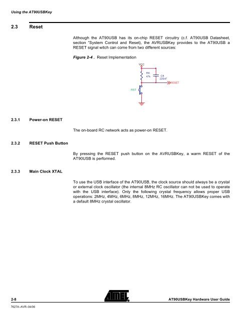
Although the AT90USB has its on-chip RESET circuitry (c.f. AT90USB Datasheet,<br />
section “System Control and Reset), the AVRUSBKey provides to the AT90USB a<br />
RESET signal witch can come from two different sources:<br />
Figure 2-4 . Reset Implementation<br />
RST<br />
VCC<br />
R6<br />
47k<br />
The on-board RC network acts as power-on RESET.<br />
C8<br />
220nF<br />
RESET<br />
By pressing the RESET push button on the AVRUSBKey, a warm RESET of the<br />
AT90USB is performed.<br />
To use the USB interface of the AT90USB, the clock source should always be a crystal<br />
or external clock oscillator (the internal 8MHz RC oscillator can not be used to operate<br />
with the USB interface). Only the following crystal frequency allows proper USB<br />
operations: 2MHz, 4MHz, 6MHz, 8MHz, 12MHz, 16MHz. The <strong>AT90USBKey</strong> comes with<br />
a default 8MHz crystal oscillator.