HI-TRAC® 100 - WIM
HI-TRAC® 100 - WIM
HI-TRAC® 100 - WIM

Create successful ePaper yourself
Turn your PDF publications into a flip-book with our unique Google optimized e-Paper software.
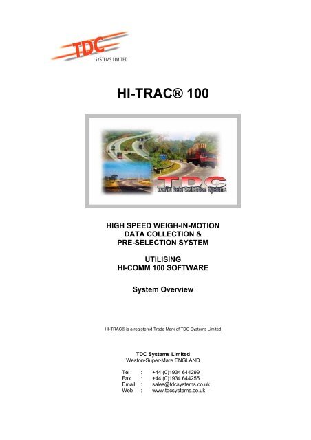
<strong>HI</strong>-<strong>TRAC®</strong> <strong>100</strong><br />
<strong>HI</strong>GH SPEED WEIGH-IN-MOTION<br />
DATA COLLECTION &<br />
PRE-SELECTION SYSTEM<br />
UTILISING<br />
<strong>HI</strong>-COMM <strong>100</strong> SOFTWARE<br />
System Overview<br />
<strong>HI</strong>-<strong>TRAC®</strong> is a registered Trade Mark of TDC Systems Limited<br />
TDC Systems Limited<br />
Weston-Super-Mare ENGLAND<br />
Tel : +44 (0)1934 644299<br />
Fax : +44 (0)1934 644255<br />
Email : sales@tdcsystems.co.uk<br />
Web : www.tdcsystems.co.uk
TDC Systems Ltd <strong>HI</strong>-<strong>TRAC®</strong> <strong>100</strong> Overview<br />
CONTENTS<br />
1 System Overview<br />
1.1 Introduction<br />
1.2 Remote Site Configuration<br />
1.3 Operating Principles<br />
1.4 <strong>HI</strong>-<strong>TRAC®</strong> <strong>100</strong> Electronic Unit<br />
1.5 System Calibration<br />
1.6 Maintenance<br />
1.7 <strong>WIM</strong> Pre-Selection Operation<br />
1.8 <strong>HI</strong>-<strong>TRAC®</strong> <strong>100</strong> Front Panel Display<br />
1.9 <strong>HI</strong>-<strong>TRAC®</strong> <strong>100</strong> Menu<br />
2 Performance and Accuracy Criteria<br />
2.1 Road Sensor Configurations<br />
2.2 Piezo-Loop-Piezo<br />
2.3 Loop-Piezo-Loop<br />
2.4 The Piezo Sensor<br />
2.5 Bicycle Sensors<br />
2.6 Why Use Piezoelectric Sensors<br />
2.7 Comparison Table for Different Types of <strong>WIM</strong> Sensors<br />
3 <strong>HI</strong>-<strong>TRAC®</strong> <strong>100</strong> Data Storage Capacity<br />
3.1 Vehicle by Vehicle Data Storage<br />
3.2 Statistical Data Files<br />
3.3 ATMS Data Files<br />
3.4 Malfunction Management Files<br />
4 <strong>HI</strong>-COMM <strong>100</strong> Software Package<br />
(Example Reports & Screen Displays)<br />
5 Drawings<br />
..2..
TDC Systems Ltd <strong>HI</strong>-<strong>TRAC®</strong> <strong>100</strong> Overview<br />
1.<br />
<strong>HI</strong>-<strong>TRAC®</strong> <strong>100</strong> SYSTEM OVERVIEW<br />
1.1 Introduction<br />
The <strong>HI</strong>-<strong>TRAC®</strong> <strong>100</strong> is a medium or high speed traffic classification and weigh-inmotion<br />
(<strong>WIM</strong>) system. The <strong>HI</strong>-<strong>TRAC®</strong> <strong>100</strong> system provides a low-cost means of<br />
recording traffic data without interruption to traffic flow. The <strong>HI</strong>-<strong>TRAC®</strong> <strong>100</strong> will detect<br />
and record traffic at speeds from 5 to at least 180 kph.<br />
The system consists of road-installed items of two piezo-electric sensors and an<br />
inductive loop per traffic lane. The <strong>HI</strong>-<strong>TRAC®</strong> <strong>100</strong> electronic unit is installed in a<br />
protective roadside cabinet and connects to the road installed items. The signal from<br />
the piezo-electric sensors is monitored by the <strong>HI</strong>-<strong>TRAC®</strong> <strong>100</strong> and used to calculate<br />
the axle loading, vehicle speed and vehicle inter-axle separation as the vehicle<br />
passes over the road sensor array.<br />
The <strong>HI</strong>-<strong>TRAC®</strong> <strong>100</strong> electronic unit monitors the inductive loop signal to determine<br />
vehicle presence time over the road sensor array and hence provides an indication of<br />
the lane occupancy. The inductive loop signal is also used by <strong>HI</strong>-<strong>TRAC®</strong> to determine<br />
vehicle chassis length and as an end-of-vehicle detector to separate closely passing<br />
traffic. A 4-line by 20-character LCD located on the front panel displays the data<br />
recorded from the last vehicle and in conjunction with a 16-key membrane keypad<br />
facilitates localised setting of configuration parameters, calibration and other<br />
functions.<br />
The system may be linked via a modem and telephone line, a GSM modem or a data<br />
(RS485) cable link to a PC for downloading of data, administration and real time<br />
viewing of traffic. Additionally a laptop computer can be connected locally via a serial<br />
(RS232) port on the front panel of the <strong>HI</strong>-<strong>TRAC®</strong> <strong>100</strong>.<br />
Data is stored internally on an SRAM memory card. The <strong>HI</strong>-<strong>TRAC®</strong> <strong>100</strong> is installed<br />
as standard with a 4Mbyte card, which will store up to 400,000 vehicle records when<br />
operating in the <strong>WIM</strong> mode. An upgrade to either a 6Mbyte or 8Mbyte memory card is<br />
available.<br />
The <strong>HI</strong>-<strong>TRAC®</strong> <strong>100</strong> electronic unit is housed in a weatherproof cabinet installed at the<br />
roadside. Power can be supplied by various means; continuous monitoring requires<br />
either AC mains or a solar panel/battery set-up, whereas temporary installations can<br />
be supplied by a battery of suitable size (dependant upon length of survey). A backup<br />
battery is normally recommended if the system is powered via AC mains.<br />
The <strong>HI</strong>-<strong>TRAC®</strong> <strong>100</strong> system utilizes the TDC Systems Neural Network Temperature<br />
Compensation Algorithm to continually fine tune temperature compensation for<br />
optimum system performance and accuracy.<br />
The standard <strong>HI</strong>-<strong>TRAC®</strong> <strong>100</strong> system connects to 4 lanes of road-installed sensors<br />
but it is upgradeable to connect to a maximum of 8 lanes.<br />
..3..
TDC Systems Ltd <strong>HI</strong>-<strong>TRAC®</strong> <strong>100</strong> Overview<br />
1.2 Remote Site Configuration<br />
The <strong>HI</strong>-<strong>TRAC®</strong> <strong>100</strong> electronic unit is capable of interfacing to sixteen piezo-electric sensors<br />
and eight inductive loops. In the standard configuration of two piezo-electric sensors and one<br />
inductive loop, per lane of traffic measuring, this provides a maximum of 8 lanes of data<br />
recording.<br />
For a weigh-in-motion (<strong>WIM</strong> system) installation of Class 1 piezo-electric sensors are<br />
preferred.<br />
For an installation that is required to only count and classify vehicles (an AVC system) Class<br />
2 piezo-electric sensors provide a more cost-effective solution.<br />
With a <strong>WIM</strong> installation it is necessary to install an in-road thermistor to provide road<br />
temperature information to the <strong>HI</strong>-<strong>TRAC®</strong> <strong>100</strong> system. This is used for temperature<br />
correction of the recorded vehicle axle load data. The <strong>HI</strong>-<strong>TRAC®</strong> <strong>100</strong> system utilizes the<br />
TDC Systems Neural Network Temperature Compensation Algorithm to continually fine tune<br />
the applied temperature compensation for optimum system performance.<br />
1.3 Operating Principles<br />
The piezo-electric sensor outputs electrical charge proportional to the applied pressure of a<br />
vehicle axle or wheel passing over it. The electrical charge is converted into a voltage, by the<br />
<strong>HI</strong>-<strong>TRAC®</strong> <strong>100</strong> electronic unit. The voltage signal is monitored by <strong>HI</strong>-<strong>TRAC®</strong> <strong>100</strong> and used<br />
to determine axle detection times. The amplitude of the signal gives an indication of axle<br />
weight.<br />
..4..
TDC Systems Ltd <strong>HI</strong>-<strong>TRAC®</strong> <strong>100</strong> Overview<br />
The piezo-electric sensors are installed a distance of 3 Metres apart in the road surface. The<br />
inductive loop is 2 Metres square. The loop is situated symmetrically between the sensors, in<br />
the lane. The time between the same axle being detected on both piezo sensors provides an<br />
axle speed measurement.<br />
The separation between each axle pair on the vehicle is calculated from the axle detection<br />
times recorded on a single sensor and multiplying by the calculated speed. For improved<br />
accuracy this result is averaged over the two sensors.<br />
The inductance value of the road-installed loop changes when a vehicle passes through the<br />
loop detection zone. This causes a change in the oscillation frequency of the loop detector<br />
circuitry inside the <strong>HI</strong>-<strong>TRAC®</strong> <strong>100</strong> electronic unit. This change in frequency is monitored by<br />
the loop detector and used to determine when vehicles are over the sensor array. The<br />
vehicle length is determined from the length of time the inductive loop was activated by the<br />
metal chassis of the vehicle.<br />
The inductive loop signal is also used to distinguish between closely moving traffic. If the<br />
loop detector output deactivates it is assumed by the <strong>HI</strong>-<strong>TRAC®</strong> system that the final axle<br />
has been detected on the first piezo sensor (that is the first sensor in the direction of traffic).<br />
This is then determined to be the total number of axles on the currently detected vehicle.<br />
Where two or more lanes are installed with sensors the <strong>HI</strong>-<strong>TRAC®</strong> <strong>100</strong> is capable of<br />
determining and recording vehicles that straddle adjacent lanes.<br />
A typical installation is shown above, however alternative sensor configurations can be<br />
employed dependant upon the application. Drawings attached at the end of this document<br />
outline the variations available.<br />
1.4 <strong>HI</strong>-<strong>TRAC®</strong> <strong>100</strong> Electronic Unit<br />
The <strong>HI</strong>-TRAC <strong>100</strong> is a rack or shelf mount unit residing in a weatherproof roadside cabinet.<br />
The unit incorporates a 16-key membrane keypad and a 4-line LCD display to facilitate<br />
configuration and set-up. In addition an RS232 (Serial) connection is provided for laptop<br />
connection.<br />
..5..
TDC Systems Ltd <strong>HI</strong>-<strong>TRAC®</strong> <strong>100</strong> Overview<br />
The <strong>HI</strong>-<strong>TRAC®</strong> <strong>100</strong> connections include:<br />
Piezo-Electric Sensor (x 16)<br />
Inductive Loop (x 8)<br />
RS232 Laptop Communication Port<br />
Modem Communication Port<br />
Modem Power Output (8V DC)<br />
Thermistor Input<br />
Relay Output<br />
RS485 Communication Port<br />
Battery Power Input (12V DC)<br />
AC Mains Input<br />
Cabinet Door Switch Input (x 2)<br />
Ticket Printer Output<br />
The vehicle data recorded by the <strong>HI</strong>-<strong>TRAC®</strong> system can be retrieved into the <strong>HI</strong>-COMM <strong>100</strong><br />
Traffic Data Collection software package via a laptop or modem connection. <strong>HI</strong>-COMM <strong>100</strong><br />
is a powerful, multi-function software package developed in-house by TDC Systems Limited.<br />
The <strong>HI</strong>-<strong>TRAC®</strong> <strong>100</strong> continues to record vehicle data whilst <strong>HI</strong>-COMM is connected to and<br />
downloading to the laptop or remote PC.<br />
All <strong>HI</strong>-<strong>TRAC®</strong> <strong>100</strong> configuration parameters can be programmed using the <strong>HI</strong>-COMM <strong>100</strong><br />
user-friendly WINDOWS based software package and can be stored into a file on the<br />
computer. They can also be uploaded from the computer to reset the <strong>HI</strong>-<strong>TRAC®</strong> <strong>100</strong> settings<br />
back to the correct values if corruption of information has taken place.<br />
A local (cable) connection can be extended over a distance of up to 1Kilometre using the<br />
RS485 communications port.<br />
The system is designed to work via the telephone network using any number of different<br />
manufacturer’s modems. A DC powered modem is recommended for operation with the <strong>HI</strong>-<br />
<strong>TRAC®</strong> <strong>100</strong> system. The <strong>HI</strong>-<strong>TRAC®</strong> <strong>100</strong> provides the DC power output to the modem. This<br />
has the advantage of the <strong>HI</strong>-<strong>TRAC®</strong> providing power cycling to the modem each hour<br />
(switching the modem off and on again and then re-initialising the modem) to prevent modem<br />
latch-up problems.<br />
..6..
TDC Systems Ltd <strong>HI</strong>-<strong>TRAC®</strong> <strong>100</strong> Overview<br />
Additionally a GSM modem with a vandal proof antenna can be installed where the system is<br />
installed in a location with no available telephone landlines.<br />
The <strong>HI</strong>-<strong>TRAC®</strong> <strong>100</strong> is capable of driving up to two external 12V DC relays. These can be<br />
used for a variety of applications including switching traffic signals or activating external<br />
alarms when vehicles are detected as being illegally loaded.<br />
The door switch input connects to the cabinet door switches mounted internally on the front<br />
and rear roadside cabinet doors. When a door is opened the <strong>HI</strong>-<strong>TRAC®</strong> <strong>100</strong> system records<br />
an entry into a log (the Malfunction Management File) stored in its internal battery-backed<br />
memory. This log can be recalled and displayed within the <strong>HI</strong>-COMM <strong>100</strong> software package<br />
providing a record of when and where <strong>HI</strong>-<strong>TRAC®</strong> cabinets have been accessed.<br />
The <strong>HI</strong>-<strong>TRAC®</strong> <strong>100</strong> runs from an AC mains supply with a wide input voltage and frequency<br />
tolerance (85-264V, 47-400Hz). The <strong>HI</strong>-<strong>TRAC®</strong> <strong>100</strong> internal power supply unit (PSU) is a<br />
universal input AC/DC converter. The output voltage of the PSU is approximately 13.8V. With<br />
a 12V sealed lead-acid rechargeable battery connected to the <strong>HI</strong>-<strong>TRAC®</strong> battery input<br />
connector the PSU trickle charges to provide a constantly topped up back-up battery. In the<br />
event of mains power failure the system continues to operate uninterrupted – in the case of a<br />
DC powered modem the system also continues to communicate uninterrupted. A mains<br />
power failure fault is recorded to a log stored in the <strong>HI</strong>-<strong>TRAC®</strong> <strong>100</strong> battery-backed memory.<br />
Alternatively where AC mains power is not available the <strong>HI</strong>-<strong>TRAC®</strong> <strong>100</strong> can be powered by a<br />
solar panel and battery set-up. Solar panels from 20-80W and 12v battery sizes from 32-<br />
80Ah may be employed, dependant upon local conditions.<br />
For relatively short duration surveys the <strong>HI</strong>-<strong>TRAC®</strong> <strong>100</strong> electronic unit may be powered by a<br />
rechargeable sealed lead-acid battery. The <strong>HI</strong>-<strong>TRAC®</strong> <strong>100</strong> will remain powered for more<br />
than 7 days hours from a 38 AH battery.<br />
..7..
TDC Systems Ltd <strong>HI</strong>-<strong>TRAC®</strong> <strong>100</strong> Overview<br />
1.5 System Calibration<br />
Calibration procedures and Temperature Non-Linearity set-up procedures are fully explained<br />
in a separate documentation but basic calibration consists of passing a number of vehicles<br />
(normally three different types) over the sensors in each lane and recording each axle and<br />
gross vehicle weight on each pass.<br />
Each vehicle is loaded to known axle and gross vehicle weights and checked at a calibrated<br />
static weighbridge prior to calibrating the HS<strong>WIM</strong> system. Wherever possible it is<br />
recommended that three vehicles are used:<br />
i) 2 Axle Rigid Vehicle Loaded to 16,000kg (approx.)<br />
ii) 3 Axle Rigid Vehicle Loaded to 25,000kg (approx.)<br />
iii) 5/6 Axle Articulated Vehicle Loaded to 35,000kg (approx.)<br />
Where these vehicles are not available it is recommended that at least one vehicle with 3 or<br />
more axles is used.<br />
The recorded axle and gross vehicle weights are compared to the weights recorded on the<br />
static weighbridge and corrections are made to ensure results are to an acceptable level of<br />
accuracy.<br />
Note that weight results are subject to variation due to a number of parameters that are<br />
independent of the electronic system; to this end site selection is paramount to system<br />
accuracy. These parameters include:<br />
i) Road condition and smoothness of the surface<br />
ii) Geometric parameters (road is on an incline or curve)<br />
iii) Vehicle change of speed (accelerating or braking)<br />
To provide the most accurate results a <strong>HI</strong>-TRAC system should be installed, commissioned<br />
and left collecting data for approximately one or two weeks after which corrections utilising<br />
the temperature non-linearity functions are made prior to the actual calibration.<br />
System re-calibration should be carried out on a 6-8 month basis.<br />
1.6 Maintenance<br />
Maintenance procedures with piezo electric sensor weigh-in-motion systems are fairly<br />
minimal when compared to other systems utilising bending plates and single load cells.<br />
Regular inspections (monthly) are recommended and consist of:<br />
i) Visual inspection of the road condition around the sensors<br />
ii) Measurement of the capacitance and resistance of the piezo electric sensors<br />
iii) Measurement of the resistance (and inductance if possible) of the inductive loop<br />
sensor<br />
iv) Check of battery condition and state of charge<br />
v) Check of system functionality via the front panel keypad and display<br />
vi) Check of vehicle record via the front panel display and visible passing traffic<br />
If the road conditions around the sensors show signs of cracking and break-up immediate<br />
repairs utilising epoxy or bituminous repair material is recommended.<br />
..8..
TDC Systems Ltd <strong>HI</strong>-<strong>TRAC®</strong> <strong>100</strong> Overview<br />
1.7 <strong>WIM</strong> Pre-Selection Operation<br />
The <strong>HI</strong>-<strong>TRAC®</strong> <strong>100</strong> can be configured to pre-select vehicles for more accurate low-speed or<br />
static weighing enforcement. A typical configuration would include a medium or high speed<br />
<strong>HI</strong>-<strong>TRAC®</strong> system located in the highway up stream of a low speed/static LO-<strong>TRAC®</strong> Axle<br />
Weighbridge Enforcement Station.<br />
<strong>HI</strong>-<strong>TRAC®</strong> <strong>100</strong> <strong>WIM</strong> pre-selection of overloaded vehicles<br />
Automatic Number Plate Recognition or CCTV and Text Insertion options<br />
Diversion sign to send overloaded vehicles to Weigh Station<br />
LO-<strong>TRAC®</strong> Axle Weighbridge for Enforcement<br />
If the <strong>HI</strong>-<strong>TRAC®</strong> system identifies a vehicle as being overloaded it can activate a Divert to<br />
Weighbridge sign.<br />
..9..
TDC Systems Ltd <strong>HI</strong>-<strong>TRAC®</strong> <strong>100</strong> Overview<br />
The vehicle diverts to the LO-<strong>TRAC®</strong> weighbridge where it is weighed to typically ±1%<br />
accuracy.<br />
The <strong>HI</strong>-<strong>TRAC®</strong> system interfaces directly to the LO-<strong>TRAC®</strong> weigh station electronics by<br />
means of an RS485 communication cable. The LO-TRAC system communicates the <strong>HI</strong>-<br />
<strong>TRAC®</strong> data to the weigh station PC for user display.<br />
The <strong>HI</strong>-<strong>TRAC®</strong> system can be equipped with CCTV. Text can be inserted onto the camera<br />
image by the <strong>HI</strong>-<strong>TRAC®</strong> <strong>100</strong> system by means of a text insertion module installed at the <strong>HI</strong>-<br />
TRAC roadside cabinet. The output can then be stored onto a time-lapsed VCR and/or<br />
displayed on a monitor at the weigh station office.<br />
Additionally a number plate recognition system may be interfaced with the <strong>HI</strong>-<strong>TRAC®</strong> for<br />
identification of infringing vehicles.<br />
..10..
TDC Systems Ltd <strong>HI</strong>-<strong>TRAC®</strong> <strong>100</strong> Overview<br />
1.8 <strong>HI</strong>-<strong>TRAC®</strong> <strong>100</strong> Front Panel Display<br />
The <strong>HI</strong>-<strong>TRAC®</strong> <strong>100</strong> displays each vehicle that is detected on the front panel LCD dialogue<br />
box. An example of the information displayed is as follows:<br />
This is the normal weighing/recording display mode of the <strong>HI</strong>-<strong>TRAC®</strong> <strong>100</strong> electronic unit.<br />
The displayed data is defined as follows: -<br />
Cat 61:4 The vehicle detected was classified as having a class index<br />
number of 4 and a class name 61 (this is the vehicle category or<br />
classification of a bus).<br />
L1 The lane number in which the vehicle was detected.<br />
35KPH The speed the vehicle was travelling at in kilometres per hour<br />
(KPH).<br />
Axles 2 The total number of axles detected on the vehicle.<br />
Time 10:20:02 The time the vehicle was detected.<br />
T4 The total traffic count for the day.<br />
ID4 The unique identifying code (serial number) assigned by <strong>HI</strong>-<br />
<strong>TRAC®</strong> <strong>100</strong> to the vehicle record stored in the system batterybacked<br />
memory.<br />
NOTE: The Classification Index Number is a unique identifying number for a type of vehicle<br />
defined by the number of axles on the vehicle, the spacing between axles on the vehicle and<br />
the overhang of the vehicle. A Category or Vehicle Classification or Class Name is an<br />
identifier for a group of unique vehicle types that fall under the same identity (e.g. A “BUS” is<br />
a category which may include several unique sub-classes defining a 2-axle bus, a 3-axle bus<br />
and a mini-bus. These sub-classes are identified by their respective class index numbers<br />
assigned by <strong>HI</strong>-TRAC).<br />
1.9 <strong>HI</strong>-<strong>TRAC®</strong> <strong>100</strong> Menu<br />
Cat 61:4,L1<br />
35KPH,Axles 2<br />
Time 10:20:02<br />
T4,ID4<br />
The <strong>HI</strong>-<strong>TRAC®</strong> <strong>100</strong> front panel incorporates a 16-key membrane keypad, which is used in<br />
conjunction with the LCD to locally set system parameters. Menu options 1-9 can be selected<br />
directly by pressing the corresponding key number; the additional options are selected via<br />
the up and down arrows on the keypad.<br />
The menu options are shown on the following page.<br />
..11..
TDC Systems Ltd <strong>HI</strong>-<strong>TRAC®</strong> <strong>100</strong> Overview<br />
Option 1 Set Time<br />
Sets the local time<br />
Option 2 Set date<br />
Sets the local date<br />
Option 3 Set ATMS Interval<br />
The ATMS time interval determines the interval over which the ATMS data<br />
file parameters are calculated and recorded.<br />
Option 4 Set lane Layout Configuration<br />
Sets the loop length, loop factor and sensor spacing for each lane<br />
Option 5 Select Piezoelectric Sensor Type<br />
Selects the manufacturer of the piezoelectric sensor installed into each lane<br />
Option 6 Edit Vehicle Classification Table<br />
Enters/edits existing classification detail for each class including a unique<br />
identification number, number of axles, inter-axle spacing and overhang<br />
Option 7 Set Communication Baud Rate<br />
Selects the communication baud rate, there are five settings between 2,400<br />
and 192,000<br />
Option 8 Configure Communications Port<br />
Selects the port to connect to a remote device for downloading data<br />
Option 9 Configure Lane Type – Lanes 1-4<br />
Sets the type of monitoring for each lane: <strong>WIM</strong>, AVC, CYC (Cycles) or<br />
optionally turns monitoring off for that lane<br />
Option 10 Configure Lane Type – Lanes 5-8<br />
Sets the type of monitoring for each lane: <strong>WIM</strong>, AVC, CYC (Cycles) or<br />
optionally turns monitoring off for that lane<br />
Option 11 Configure Thermistor<br />
Sets temperature coefficient and calibrates the thermistor<br />
Option 12 System Voltage Monitor<br />
The <strong>HI</strong>-<strong>TRAC®</strong> <strong>100</strong> monitors the supply voltage and reports supply failures<br />
Option 13 Modem Power Reset & Initialisation<br />
Manually resets the modem by turning off its power then turns it on again<br />
Option 14 Cabinet Door Switch Status<br />
Indicates the status of the door switches<br />
Option 15 Set Lane Direction – Lanes 1-4<br />
Sets the traffic direction: North/South/East/West<br />
Option 16 Set Lane Direction – lanes 5-8<br />
Sets the traffic direction: North/South/East/West<br />
Option 17 Set <strong>WIM</strong> Calibration Factor<br />
Sets the calibration factor for each lane<br />
..12..
TDC Systems Ltd <strong>HI</strong>-<strong>TRAC®</strong> <strong>100</strong> Overview<br />
2.<br />
PERFORMANCE AND ACCURACY CRITERIA<br />
General Performance Data:<br />
Speed Range : 5 to at least 200 KPH<br />
Storage Capacity : 4 Mbytes (Upgrade 6M, 8M)<br />
Vehicle-by-Vehicle Storage : 400,000 <strong>WIM</strong> records (4Mbytes)<br />
Lane Capacity <strong>WIM</strong>/AVC : 8 Lanes<br />
Statistical File Storage : 150 days<br />
ATMS File Storage : 50 Intervals<br />
BINNED Data Storage : 8 Bins, 1400 Intervals<br />
Telemetry Options : GSM, PSTN, GPRS<br />
Temperature Range : -20C to +65C<br />
Classification : EURO 6 (default)<br />
User Configurable : 110 Vehicle Classes<br />
<strong>WIM</strong>/AVC Accuracy:<br />
Piezo-Loop-Piezo : ±10% GVW<br />
Piezo-Loop-Piezo : ±15% Axle Group<br />
Piezo-Loop-Piezo : ±20% Axle Weight<br />
Weight accuracies stated to 95% Confidence or Probability of Conformity.<br />
(NOTE: Weight accuracies of
TDC Systems Ltd <strong>HI</strong>-<strong>TRAC®</strong> <strong>100</strong> Overview<br />
Classification Accuracy (based on DfT Scheme):<br />
Class 0: Motorbike<br />
Loop + Piezo<br />
95%<br />
Class 1: Cars 97%<br />
Class 2: Vans 97%<br />
Class 21: Car/Van + Trailer/Caravan 97%<br />
Class 31: 2 Axle Rigid Truck 98%<br />
Class 32: 3 Axle Rigid Truck 98%<br />
Class 33: 4 Axle Rigid Truck 99%<br />
Class 41: 3 Axle Drawbar Trailer 99%<br />
Class 42: 4 Axle Drawbar Trailer 99%<br />
Class 43: 5 Axle Drawbar Trailer 99%<br />
Class 44: 6 Axle Drawbar Trailer 99%<br />
Class 51: 3 Axle Articulated Truck 99%<br />
Class 52: 4 Axle Articulated Truck (1+1+2) 99%<br />
Class 53: 4 Axle Articulated Truck (1+2+1) 99%<br />
Class 54: 5 Axle Articulated Truck (1+2+2) 99%<br />
Class 55: 5 Axle Articulated Truck (1+1+3) 99%<br />
Class 56: 6 Axle Articulated Truck 99%<br />
Class 61: Buses and Coaches 97%<br />
Class 7: 7 or More Axle Vehicle 99%<br />
Class CY: Bicycles (separate sensors required) 95%<br />
..14..
TDC Systems Ltd <strong>HI</strong>-<strong>TRAC®</strong> <strong>100</strong> Overview<br />
2.1 Road Sensor Configurations<br />
There are many different road sensor configurations for traffic classification, counting and<br />
weigh-in-motion recording. Each configuration has its own accuracy criteria. The sensor<br />
configuration selected for a particular installation should be based on the accuracy<br />
requirement, site of installation, ease of installation, maintainability, reliability and cost.<br />
TDC Systems Limited recommends the Piezo-Loop-Piezo installation for the highest quality<br />
vehicle classification, speed and axle weight data.<br />
Loop-Piezo-Loop configuration provides for AVC and <strong>WIM</strong> functionality with only a single<br />
piezo sensor for axle weight measurement.<br />
NOTE: Accurate axle weight data can only be acquired if the installation site is located in a<br />
smooth, flat road surface with minimum curvature and no rutting for 50 metres before and 20<br />
metres after the installation, with respect to direction of traffic flow.<br />
2.2 Piezo-Loop-Piezo<br />
The piezo-loop-piezo system incorporates two piezo-electric sensors, installed in a lane, 3<br />
Metres apart with a 2 Metre square inductive loop symmetrically between them.<br />
Vehicle speed measurement is performed by measuring the axle detection times on the two<br />
piezo-electric sensors. This technique gives an absolute speed measurement of each axle<br />
on the vehicle.<br />
Similarly the axle separation is calculated from axle detection times on the same sensor. This<br />
is the most accurate axle space measurement technique of all the different road sensor<br />
configurations.<br />
Speed accuracy for the piezo-loop-piezo sensor array is quoted at better than ±1.5%.<br />
For a <strong>HI</strong>-<strong>TRAC®</strong> <strong>100</strong> AVC Counting/Classifying system either full-size or half-size sensors<br />
can be employed. Full-size sensors span the entire width of the traffic lane (typically<br />
3.35Metres). Half-size sensors span a sufficient portion of the lane to cover a single wheel<br />
track (typically 1.8Metres). For the AVC system there is a small improvement in vehicle<br />
detection for the full-size sensor array.<br />
For a <strong>HI</strong>-<strong>TRAC®</strong> <strong>100</strong> <strong>WIM</strong> system it is recommended that full-size Class 1 piezo-electric<br />
sensors are used. With full-size sensors, each wheel on the vehicle passes over the piezo<br />
sensor, giving an output proportional to the weight of the wheel. This provides complete axle<br />
load information to the <strong>HI</strong>-<strong>TRAC®</strong> <strong>100</strong> system. With the half-size sensor solution the <strong>HI</strong>-<br />
<strong>TRAC®</strong> <strong>100</strong> has to assume that the wheel weights on the same axle are the same and<br />
effectively double the wheel weight to attain the axle weight.<br />
For a full-size Class 1 piezo sensor installation with a piezo-loop-piezo configuration (on a<br />
smooth road surface as defined above) axle weight accuracy of ±7% are achievable with a<br />
95% confidence limit.<br />
..15..
TDC Systems Ltd <strong>HI</strong>-<strong>TRAC®</strong> <strong>100</strong> Overview<br />
2.3 Loop-Piezo-Loop<br />
The loop-piezo-loop system incorporates two inductive loops, installed in a lane, 2.5 Metres<br />
apart with a piezo-electric sensor located symmetrically between them.<br />
Vehicle speed measurement is performed by measuring the vehicle detection times on the<br />
two inductive loops.<br />
Similarly the axle separation is calculated from axle detection times on the sensor.<br />
Speed accuracy for the loop-piezo-loop sensor array is quoted at ±1.5%, providing the<br />
vehicle travels centrally in the lane.<br />
For a <strong>HI</strong>-<strong>TRAC®</strong> <strong>100</strong> AVC Counting/Classifying system utilising the Loop-Piezo-Loop<br />
configuration either full-size or half-size sensors can be employed. Full-size sensors span the<br />
entire width of the traffic lane (typically 3.35Metres). Half-size sensors span a sufficient<br />
portion of the lane to cover a single wheel track (typically 1.8Metres). There is a small<br />
improvement in vehicle detection with the full-size sensor array.<br />
For a <strong>HI</strong>-<strong>TRAC®</strong> <strong>100</strong> <strong>WIM</strong> system it is recommended that full-size Class 1 piezo-electric<br />
sensors are used. With full-size sensors, each wheel on the vehicle passes over the piezo<br />
sensor, giving an output proportional to the weight of the wheel. This provides complete axle<br />
load information to the <strong>HI</strong>-<strong>TRAC®</strong> <strong>100</strong> system. It is not recommended to use half-size<br />
sensors in a <strong>WIM</strong> application<br />
For a full-size Class 1 piezo sensor installation with a loop-piezo-loop configuration (on a<br />
smooth road surface as defined above) axle weight accuracies of ±15% are achievable with<br />
a 95% confidence limit.<br />
2.4 Vehicle Classification<br />
Vehicle classification is determined from the number of axles on a vehicle, the separation<br />
between each pair of axles on the vehicle and the overhang of the vehicle. The axle<br />
separation is calculated to within ±2% with both piezo-loop-piezo and loop-piezo-loop<br />
configuration.<br />
The piezo-loop-piezo system accurately detects and classifies vehicles that straddle the<br />
sensor array, i.e. vehicles that are travelling between lanes.<br />
Vehicle length accuracy is measured with an accuracy of ±8%.<br />
..16..
TDC Systems Ltd <strong>HI</strong>-<strong>TRAC®</strong> <strong>100</strong> Overview<br />
2.5 The Piezo Sensor<br />
The piezo sensor recommended by TDC Systems Limited is the Roadtrax BL sensor. The<br />
specification is as follows:<br />
Output Uniformity: < ±7% for Class I (<strong>WIM</strong>)<br />
< ±20% for Class II (AVC)<br />
Output Temperature Range -40 to +80°C<br />
Temperature Sensitivity ±0.1% per °C<br />
Product Life 40,000,000 Equivalent Standard Axle Load’s<br />
(dependent on installation)<br />
The unique construction of the BL sensor allows it to be installed directly into the road in a<br />
flexible format so that it can conform to the profile of the road.<br />
The flat construction of the sensor gives an inherent rejection of road noise due to the road<br />
bending effect of an approaching axle and signal detection from adjacent lane activity.<br />
The small cut size (19mm by 19mm slot) in the road minimises the damage which is done to<br />
the road, speeds up the installation time and reduces the amount of epoxy that is used for<br />
the installation.<br />
For the Weigh-in-Motion installation temperature compensation of the piezo-electric output<br />
signal is required for most accurate weight measurement. This is achieved by means of a<br />
road-installed temperature sensor probe. The temperature probe is monitored by the <strong>HI</strong>-<br />
<strong>TRAC®</strong> <strong>100</strong> electronic unit.<br />
The <strong>HI</strong>-<strong>TRAC®</strong> <strong>100</strong> system is calibrated with a selection of vehicles whose static axle<br />
weights are accurately recorded at a low-speed (or static) weighbridge.<br />
2.6 Bicycle Sensors<br />
The <strong>HI</strong>-<strong>TRAC®</strong><strong>100</strong> can be configured to connect to bicycle detection sensors. Two piezoelectric<br />
sensors are installed 1 metre apart per bicycle lane.<br />
The bicycle sensors can also be installed in a normal traffic lane. The <strong>HI</strong>-<strong>TRAC®</strong><strong>100</strong> filters<br />
the normal traffic and only detects bicycles. The filtering function measures the signal size of<br />
passing axles to distinguish between bicycles and normal traffic. The speed and axle spacing<br />
provide a further distinction.<br />
If bicycle sensors are installed in a normal traffic lane the <strong>HI</strong>-<strong>TRAC®</strong><strong>100</strong> is programmed to<br />
filter out simultaneous detections of bicycles, mopeds and motorbikes so not to record the<br />
same vehicle twice.<br />
..17..
TDC Systems Ltd <strong>HI</strong>-<strong>TRAC®</strong> <strong>100</strong> Overview<br />
2.7 Why Use Piezoelectric Sensors?<br />
TDC recommends the BL® piezoelectric sensor for most <strong>WIM</strong> applications including preselection<br />
for enforcement and data collection. The BL sensor gives accuracy of ±10% for<br />
95% of vehicles providing the sensor is installed in a smooth flat road surface.<br />
The installation is simple and can be carried out in 3 hours per lane, meaning minimal road<br />
closure times.<br />
The sensors are fully encapsulated in resin and do not exhibit the problem of flush mounted<br />
sensors, where resin break up in the wheel track areas causes the sensor to work free over a<br />
period of time. These sensors require regular maintenance in the form of resin repairs and<br />
cause break up of the road surface around the array.<br />
The sensor cost, installation cost and associated maintenance costs are considerably lower<br />
than other proven <strong>WIM</strong> technologies available now.<br />
..18..
TDC Systems Limited <strong>HI</strong>-<strong>TRAC®</strong><strong>100</strong> Overview<br />
3.<br />
<strong>HI</strong>-<strong>TRAC®</strong> DATA STORAGE CAPACITY<br />
3.1 Vehicle-by-Vehicle Data Storage<br />
Vehicle-by-Vehicle (VBV) data refers to data stored in the <strong>HI</strong>-TRAC battery-backed memory<br />
for each individual vehicle that is detected by the system. The system stores data on every<br />
vehicle detected by the system for 8 days. At the start of the next day (9 th day), data recorded<br />
on the first day is overwritten hence there is always 7 full days data stored and available for<br />
download.<br />
The <strong>HI</strong>-TRAC electronic unit provides 4 Megabytes of Vehicle-by-Vehicle (VBV) data<br />
storage. An average of 10 bytes (<strong>WIM</strong> or 6 bytes (AVC) required to store all of the recorded<br />
data for a vehicle with all VBV parameters selected for storage the total capacity of the<br />
system is approximately 400,000 (<strong>WIM</strong>) or 600,000 (AVC) vehicles. Parameters stored on a<br />
vehicle-by-vehicle basis include:<br />
Date<br />
Time<br />
Serial Number (unique ID number)<br />
Number of Axles<br />
Vehicle Classification Index<br />
Vehicle Category<br />
Lane Number<br />
Direction<br />
Vehicle Straddling<br />
Validity Code<br />
Road Surface Temperature<br />
Individual Axle Weights (ESA)<br />
Gross Vehicle Weight<br />
Inter-Vehicle Spacing (Gap)<br />
Headway (time between subsequent vehicle detections on same lane)<br />
Vehicle Length<br />
The parameters stored with each VBV data record are configurable, by lane, from within the<br />
<strong>HI</strong>-COMM <strong>100</strong> software package. This provides a means of optimising the memory storage<br />
inside the <strong>HI</strong>-<strong>TRAC®</strong><strong>100</strong> for the vehicle data of interest. To help the operator determine<br />
memory allocation and number of days of required storage a <strong>HI</strong>-<strong>TRAC®</strong><strong>100</strong> memory map is<br />
graphically displayed from within the <strong>HI</strong>-COMM <strong>100</strong> software.<br />
..19..
TDC Systems Limited <strong>HI</strong>-<strong>TRAC®</strong><strong>100</strong> Overview<br />
3.2 Statistical Data Files<br />
The <strong>HI</strong>-<strong>TRAC®</strong><strong>100</strong> stores in battery-backed memory statistical data files for the previous 150<br />
days of <strong>HI</strong>-<strong>TRAC®</strong><strong>100</strong> operation. These data files include the following information:<br />
Average Speed per Vehicle Category per Lane per Day<br />
Traffic Volume per Vehicle Category per Lane per Day<br />
Traffic Volume per Hour per Lane per Day<br />
Average Gross Weight per Category per Lane per Day<br />
Axle Volume per Weight Band per Lane per Day<br />
A vehicle category is a group of vehicle classifications, for example all buses may fall under<br />
the title “BUSES” (or Class “61”) whether they are 2 axle, 3 axle, mini-buses or coaches.<br />
3.3 ATMS Data Files<br />
ATMS (Advanced Traffic Management System) data files store vehicle data and fault<br />
monitoring information over a configurable time period from 1 minute to 12 hours. The data<br />
stored in each ATMS file includes:<br />
Start Date of ATMS interval<br />
Start Time of ATMS interval<br />
Period of ATMS interval<br />
Diagnostic Code for ATMS interval<br />
Occupancy per Lane for ATMS Interval<br />
Average Speed per Category per Lane for ATMS Interval<br />
Traffic Volume per Category per Lane for ATMS interval<br />
The <strong>HI</strong>-<strong>TRAC®</strong> <strong>100</strong> stores 50 ATMS files for the previous 50 ATMS intervals. The oldest<br />
data file is overwritten at the start of a new ATMS interval.<br />
A diagnostic code is stored with each ATMS file. This gives an indication of any system<br />
errors that may have occurred during the ATMS interval. To view the definition of diagnostic<br />
code, from within the <strong>HI</strong>-COMM <strong>100</strong> software package, click on the ATMS record of interest<br />
and press CTRL and F1 simultaneously. A window appears with definitions of the code.<br />
The diagnostic code is 4 bytes in size. Each bit within the diagnostic code has a definition:<br />
..20..
TDC Systems Limited <strong>HI</strong>-<strong>TRAC®</strong><strong>100</strong> Overview<br />
3.4 Malfunction Management Data Files<br />
Malfunction management data files are stored on the <strong>HI</strong>-<strong>TRAC®</strong> for the previous 8 days (the<br />
8 th data file being overwritten at the start of a new day).<br />
The malfunction data file contains information on mains power failures, communication<br />
errors, sensor failures, loop failures and cabinet doors opening.<br />
When <strong>HI</strong>-COMM <strong>100</strong> connects to a <strong>HI</strong>-<strong>TRAC®</strong> <strong>100</strong> system it downloads this file. If a new<br />
error condition is detected in the malfunction management file a fault log database<br />
(Fault.mdb) on the PC located in the application directory is updated with the fault condition.<br />
The ‘View Malfunction Management’ icon illuminates to indicate a new fault has been<br />
detected.<br />
Diagnostic Codes<br />
..21..
TDC Systems Limited <strong>HI</strong>-<strong>TRAC®</strong><strong>100</strong> Overview<br />
4<br />
EXAMPLE REPORTS & SCREEN DISPLAYS<br />
4.1 Examples of <strong>HI</strong>-COMM <strong>100</strong> Software Screen Displays<br />
Typical software screen displays to help illustrate the functionality and comprehensive<br />
features of the <strong>HI</strong>-COMM <strong>100</strong> software package are portrayed on the following pages.<br />
<strong>HI</strong>-COMM <strong>100</strong> Opening Screen (Connected to <strong>HI</strong>-<strong>TRAC®</strong> <strong>100</strong>)<br />
Communications Parameters<br />
<strong>HI</strong>-<strong>TRAC®</strong> <strong>100</strong> Configuration<br />
VBV Data Retrieval<br />
VBV Real Time Traffic Display<br />
VBV Real Time Display Configuration<br />
Diagnostic Functions – Sensor Test, Waveforms & Codes<br />
Axle Weight & Speed Band Limits<br />
Vehicle Classification Configuration & Weight Limits<br />
ESA Parameters<br />
VBV Memory Allocation & Data Conversion<br />
4.2 Examples of Reports<br />
The following pages portray examples of just some of the reports currently available in the<br />
<strong>HI</strong>-COMM <strong>100</strong> software package.<br />
Reports Selection, Configuration & Criteria<br />
Report Sample:- Volume per Class per Lane<br />
Report Sample:- Average Speed per Class per Lane<br />
Report Sample:- Volume per Lane per Time Band<br />
Report Sample:- AEF & ESA per Weight Band per Lane<br />
Report Sample:- Damage Factor<br />
Report Sample:- Volume per Speed Band per Lane<br />
Report Sample:- Volume per Speed Band per Time Band including Percentile<br />
Speed<br />
Report Sample:- Overloaded Vehicles per Class per Lane<br />
Statistical Report Sample:- Average Speed per Category<br />
Malfunction Management Report Sample<br />
ATMS Report Sample:- Traffic Volume by Category by Lane<br />
..22..
TDC Systems Limited <strong>HI</strong>-<strong>TRAC®</strong><strong>100</strong> Overview<br />
<strong>HI</strong>-COMM <strong>100</strong> SET-UP & CONFIGURATION<br />
<strong>HI</strong>-COMM <strong>100</strong> Software<br />
(<strong>HI</strong>-<strong>TRAC®</strong> Connected)<br />
Communications Parameters<br />
..23..
TDC Systems Limited <strong>HI</strong>-<strong>TRAC®</strong><strong>100</strong> Overview<br />
<strong>HI</strong>-<strong>TRAC®</strong> <strong>100</strong> Configuration<br />
(VBV Data Storage Configuration)<br />
VBV Data Retrieval<br />
..24..
TDC Systems Limited <strong>HI</strong>-<strong>TRAC®</strong><strong>100</strong> Overview<br />
VBV Real Time View<br />
VBV Real Time Display Options<br />
..25..
TDC Systems Limited <strong>HI</strong>-<strong>TRAC®</strong><strong>100</strong> Overview<br />
Diagnostic Functions<br />
Sensor Waveform & Sensor Test Functions<br />
..26..
TDC Systems Limited <strong>HI</strong>-<strong>TRAC®</strong><strong>100</strong> Overview<br />
Diagnostic Functions<br />
(Loop Signature – Car)<br />
..27..
TDC Systems Limited <strong>HI</strong>-<strong>TRAC®</strong><strong>100</strong> Overview<br />
Axle Weight Band Limits<br />
Speed Band Limits<br />
..28..
TDC Systems Limited <strong>HI</strong>-<strong>TRAC®</strong><strong>100</strong> Overview<br />
Vehicle Classification Table<br />
(Axle Weight Limits Per Class)<br />
Class Gross Weight Limits<br />
..29..
TDC Systems Limited <strong>HI</strong>-<strong>TRAC®</strong><strong>100</strong> Overview<br />
ESA Calculation Parameters<br />
VBV Memory Allocation<br />
VBV Data Conversion<br />
..30..
TDC Systems Limited <strong>HI</strong>-<strong>TRAC®</strong><strong>100</strong> Overview<br />
<strong>HI</strong>-COMM <strong>100</strong> REPORT SAMPLES<br />
Reports Selection<br />
..31..
TDC Systems Limited <strong>HI</strong>-<strong>TRAC®</strong><strong>100</strong> Overview<br />
Reports Criteria<br />
(Selectable Time Periods)<br />
Volume Per Class Per Lane<br />
..32..
TDC Systems Limited <strong>HI</strong>-<strong>TRAC®</strong><strong>100</strong> Overview<br />
Average Speed Per Class Per Lane<br />
..33..
TDC Systems Limited <strong>HI</strong>-<strong>TRAC®</strong><strong>100</strong> Overview<br />
Volume Per Lane Group Per Time Band<br />
..34..
TDC Systems Limited <strong>HI</strong>-<strong>TRAC®</strong><strong>100</strong> Overview<br />
Axle Volume / Total Axle Weight / ESA<br />
Damage Factor<br />
Volume Per Speed Band Per Lane<br />
..35..
TDC Systems Limited <strong>HI</strong>-<strong>TRAC®</strong><strong>100</strong> Overview<br />
Traffic Volume Per Speed Band Per Time<br />
(Including Percentile Speed)<br />
Overloaded Vehicles Per Class Per Lane<br />
..36..
TDC Systems Limited <strong>HI</strong>-<strong>TRAC®</strong><strong>100</strong> Overview<br />
Statistical Data File<br />
Malfunction Management File<br />
ATMS Data File<br />
..37..
TDC Systems Limited <strong>HI</strong>-<strong>TRAC®</strong><strong>100</strong> Overview<br />
5<br />
DRAWINGS<br />
5.1 10-<strong>100</strong>3 – Multiple <strong>HI</strong>-TRAC Installation<br />
5.2 10-<strong>100</strong>4 – Outstation System Configuration<br />
5.3 10-<strong>100</strong>6 – <strong>HI</strong>-<strong>TRAC®</strong> <strong>100</strong> Front & Back Panels<br />
5.4 10-<strong>100</strong>9 – <strong>WIM</strong> Sensor Installation – Piezo/Loop/Piezo<br />
5.5 10-<strong>100</strong>9A – <strong>WIM</strong>/AVC Sensor Installation – Inlaid Piezo Sensors<br />
5.6 10-<strong>100</strong>9C – <strong>WIM</strong>/AVC Sensor Installation – Loop/Piezo/Loop<br />
5.7 10-<strong>100</strong>1 – 6-Lane <strong>WIM</strong> Layout<br />
5.8 <strong>100</strong>00-1-A – <strong>HI</strong>-TRAC Pre-Selection with CCTV/LPR Option<br />
5.9 10-<strong>100</strong>2 – BL Sensor Installation<br />
5.10 10-<strong>100</strong>8 – Loop Sensor Installation<br />
5.11 10-<strong>100</strong>7 – Roadside Cabinet General Layout<br />
5.12 97041-1 – High Speed Pre-Selection – General Layout<br />
5.13 97041-2 – Low Speed Axle Weighing – General Layout<br />
5.14 99050-1 – Pre-Selection & Weigh Station – General Layout<br />
..38..
TDC Systems Limited <strong>HI</strong>-<strong>TRAC®</strong><strong>100</strong> Overview<br />
..39..
TDC Systems Limited <strong>HI</strong>-<strong>TRAC®</strong><strong>100</strong> Overview<br />
..40..
TDC Systems Limited <strong>HI</strong>-<strong>TRAC®</strong><strong>100</strong> Overview<br />
..41..
TDC Systems Limited <strong>HI</strong>-<strong>TRAC®</strong><strong>100</strong> Overview<br />
..42..
TDC Systems Limited <strong>HI</strong>-<strong>TRAC®</strong><strong>100</strong> Overview<br />
..43..
TDC Systems Limited <strong>HI</strong>-<strong>TRAC®</strong><strong>100</strong> Overview<br />
..44..
TDC Systems Limited <strong>HI</strong>-<strong>TRAC®</strong><strong>100</strong> Overview<br />
..45..
TDC Systems Limited <strong>HI</strong>-<strong>TRAC®</strong><strong>100</strong> Overview<br />
..46..
TDC Systems Limited <strong>HI</strong>-<strong>TRAC®</strong><strong>100</strong> Overview<br />
..47..
TDC Systems Limited <strong>HI</strong>-<strong>TRAC®</strong><strong>100</strong> Overview<br />
..48..
TDC Systems Limited <strong>HI</strong>-<strong>TRAC®</strong><strong>100</strong> Overview<br />
..49..
TDC Systems Limited <strong>HI</strong>-<strong>TRAC®</strong><strong>100</strong> Overview<br />
..50..<br />
DIVERT TO<br />
WEIGH STATION
TDC Systems Limited <strong>HI</strong>-<strong>TRAC®</strong><strong>100</strong> Overview<br />
..51..
TDC Systems Limited <strong>HI</strong>-<strong>TRAC®</strong><strong>100</strong> Overview<br />
..52..<br />
ENTER<br />
WEIGHBRIDGE<br />
STATION